Vibration Analysis of a Drillstring in Horizontal Well
Xiaohua Zhu,Li Zeng and Bo Li
1School of Mechanical Engineering,Southwest Petroleum University Chengdu,Chengdu,610500,China.
Abstract: The complicated geological conditions will bring great challenges to the drillstring of horizontal wells for the reason that the increase of the well depth in Sichuan- Chongqing region.Since drillstring failure and friction during drilling are generally caused by drillstring vibration,great importance must be attached to computer simulation methods for the prediction of drillstring vibration.A finite element model considering axial,lateral and torsional vibration is established.In order to verify the established numerical model,an indoor experimental device based on the similarity principle was established.The vibration characteristics of three shale gas horizontal wells drillstrings are described.The reasons for the large difference in vibration characteristics between the three wells were discussed by changing the well structure,BHA(bottom hole assembly) and drilling parameters.The simulation results show that the depth of ultra-deep well 3 is only 1.27 times of that of medium-deep well 2,but the fluctuation of WOB (weight on bit) is 2.8 times.The primary factor for the great difference of WOB fluctuation is the change of vertical section depth,the secondary factor is the change of the horizontal section length.Additionally,the reasonable range of speeds has been proposed and applied in the field.The advantage of this numerical analysis method is that it can judge the vibration and friction torque of drillstring in horizontal wells with arbitrary structure,drilling parameters and BHA.This method has certain guiding significance to the field practice.
Keywords:Horizontal well,drillstring vibration,friction torque,fatigue life.
1 Introduction
With the development of shale gas,coalbed gas and other new hydrocarbon resources,drilling engineering is facing more complex formation environment.Directional wells and horizontal wells have been developed and applied rapidly [Tian,Yang and Yang (2017)].During horizontal well drilling,the drillstring is not only affected by its own gravity,but also by the collision and friction between the drillstring and the borehole,the vibration and friction between the bit and the rock,and the influence of the mud drilling fluid [Chen and Ren (2017)].Typically,the drillstring usually experiences three types of vibrations,namely axial vibration,torsional vibration and lateral vibration [Qiu,Yang,Butt et al.(2017)].The coupled vibration is an important cause of failure of the drillstring and safety accidents [Zhu,Jia and Tong (2012)].When the coupling vibration frequency is consistent with the drillstring natural frequency,the larger the amplitude of shock,the greater the damage of drillstring [Liu and Gao (2017)].
So far,researchers have done a lot of research on numerical models and experiments of drillstring vibration.Zamanian et al.[Zamanian,Khadem and Ghazavi (2007)] established a discrete element model with two torsional degrees of freedom and one axial degree of freedom.According to the rock interaction law of the bit,the friction contact and cutting process of the rock surface of the bit are considered.He thinks the torsional-axial vibration is due to this law.Gulyayev et al.[Gulyayev,Gaidaichuk,Solovjov et al.(2009)] explored the quasi-static stability of the drillstring under torque,axial force,rotational inertia and mud.The model was used to extract the natural frequency and mode shape of the drillstring.Germay et al.[Germay,Van de Wouw,Nijmeijer et al.(2009)],a lumped parameter model considering the axial and torsional vibration modes of bits was developed.These vibrations were coupled through a bit-rock interaction law.Yigit et al.[Yigit and Christoforou (1998)] proposed a dynamic model of coupled vibration of a drillstring.It was assumed that the bit/stratigraphic interaction is related to the motion of the bit,resulting in a set of highly nonlinear equations with self-excited states.The model was capable of capturing the rolling of the drill collar along the borehole wall.Leine et al.[Leine,Van Campen and Keultjes (2002)] proposed a simple stick-slip rotation model consisting of a sub-model of rotational motion and a sub-model of slip motion,which attempted to explain the complex behavior of drillstring motion in oil wells when both torsional stick-slip and lateral vortex-induced vibration occur simultaneously.Richard et al.[Richard,Germay and Detournay (2007)] studied the self-excited stick-slip vibration of a rotary drilling system with a bit by using the discrete model considering the axial and torsional vibration modes of the system.Using perturbation technique,Sahebkar et al.[Sahebkar,Ghazavi,Khadem et al.(2011)] established a nonlinear model of deviated well drillstring system with axial motion and axial load.The drillstring was considered as a simply supported axially moving rotor.Governing equations of motion were obtained based on Hamilton’s principle and method of multiple scales was employed to solve the nonlinear motion equations in order to obtain the steady state response and stability region of the system.Trindade et al.[Trindade,Wolter,Sampaio et al.(2005)] used the nonlinear finite element model proposed by the predecessors to calculate the nonlinear strain-displacement relationship.In order to better understand this nonlinear coupled vibration problem,Karlhen-Loif decomposition (also called proper orthogonal decomposition) is applied to its simulation dynamics.Khulief et al.[Khulief and Al-Naser (2005)] used the finite element method to establish a dynamic model of the drillstring including the drill pipe and the drill collar.The drillstring components with circular cross-section were discretized into a number of finite shaft elements with 12 degrees of freedom each.The model accounted for the gyroscopic effect,the torsional/bending inertia coupling,and the effect of the gravitational force field.Ghasemloonia et al.[Ghasemloonia,Geoff Rideout and Butt (2013)] studied the axiallateral coupling vibration behavior of the entire drill string under the action of the VARD (vibration-assisted rotary drilling) tool,established the dynamic finite element model (FEM) of the vertical drill string assuming a multi-span drill string combination,and verified it with the coupled nonlinear axial-lateral elastic dynamics mathematical model.The model includes the effects of mud damping,drive torque,multi-span contact and spatial variations on axial loads.But the model cannot capture torsional vibrations.Kapitaniak et al.[Kapitaniak,Hamaneh,Chávez et al.(2015)] developed an experimental bench that can display all drillstring vibrations,and established a drilling rig model with the finite element method to verify the predictive ability of the numerical model when stick-slip vibration occurs.Sarker et al.[Sarker,Rideout and Butt (2017)] presented a model to analyze the dynamics of a horizontal oilwell bottom-hole-assembly.A nonlinear three-dimentional multibody shaft model has been verified and extended to include stickslip whirl phenomena due to the contact between the rotating bottom-hole-assembly and wellbore.The pipe and collars are modeled using a lumped-segment approach that predicts axial and torsional motions.Feng et al.[Feng,Vadali,Ma et al.(2017)] proposed a sixdegree-of-freedom finite element model to describe drillstring dynamics.It mainly focuses on the eccentricity of BHA,mud damping,bit-rock interaction and their coupling mechanism.It has guiding significance for stick-slip vibration and rotary vibration.The models established by the above two scholars are mainly BHA rather than full-well coupled vibration model.Chen et al.[Chen,Fu,Ma et al.(2018)] proposed a non-linear coupled bottom hole assembly (BHA) bit-formation-wellbore model for BHAs with bent-housing positive displacement motor using the finite element method to investigate the dynamic behavior and steering ability under fully rotary drilling.Wang et al.[Wang,Ren,Yao et al.(2019)] used Hamilton principle of energy method to derive the drill string motion equation,and studied the influence of axial excitation and torque excitation on bit-bounce in horizontal wells with finite element method.The friction and fluid-solid coupling between drill string and borehole wall are considered in the model.He found that the bit-bounce can be achieved by applying larger rotational speeds and axial loads.
The model researchers established above generally consider only a single vibration or a coupling of two vibrations that rarely consider the coupling of axial,lateral,and torsional vibrations.However,coupling vibration often occurs during drilling.Moreover,the finite element numerical model of the whole well section is more suitable to the field practice.Therefore,in this paper,fully coupled vibration model is established to analyze the dynamic characteristics of drillstring in horizontal wells.An indoor experimental device is built to calibrate the correctness of the model.With the construction of two national shale gas demonstration zones in Changning,Sichuan and Fuling,Chongqing,the Sichuan- Chongqing region is already the main producing area for oil and gas production in China.The recoverable shale gas resources in sichuan basin can reach 4.4×10¹²m3,which is the most abundant shale gas resources in China.The shale gas in this area is characterized by thick strata and deep burial.The average thickness of shale section is 48.30 m,and the buried depth is 1500-3700 m [Wu (2019)].At present,the horizontal wells in the Sichuan- Chongqing region are usually around 7,000 m,the vertical depth is mostly 4,000 m,and the horizontal section length is about 1000-1500 m,which may even be longer in the future.In this oil and gas area,engineering problems such as drillstring failure and friction caused by excessive vibration often occur.Drillstring fatigue failure is the most common and expensive type of failure in the drilling industry,resulting in lost operating costs,time and resources [Ojanomare,Cornetti,Romagnoli et al.(2017)].The establishment of coupling vibration model of horizontal well is helpful to better understand the vibration characteristics of drillstring in Sichuan-Chongqing area,so as to avoid the failure of drillstring.The numerical model can analyze the vibration and friction torque of drillstring under arbitrary wellbore structure,drilling parameters and BHA.Compared with previous studies by scholars,the whole well section drillstring numerical model is closer to the field practice.In this paper,the vibration characteristics of three wells are analyzed in detail,as well as the fundamental reasons that lead to the huge difference in the fluctuation of WOB of three wells,and the reasonable speed range is obtained (Sections 3.2-3.3).Additionally,fatigue life prediction of drillstring can play an important role in early warning of failure (Section 3.4).The conclusion of this study is of guiding significance for practical drilling.
2 Model description and experiments calibration
2.1 Theoretical models
Considering the influence of circulating medium and the boundary conditions of the borehole wall and the upper and lower boundary conditions,the mechanical model of the lateral,axial and torsional coupled vibration of the drillstring is established by the energy method.In this paper,the drillstring system is simplified as a collection of mass spring elements with multiple degrees of freedom (Fig.1) [Zhu and Li (2019)].
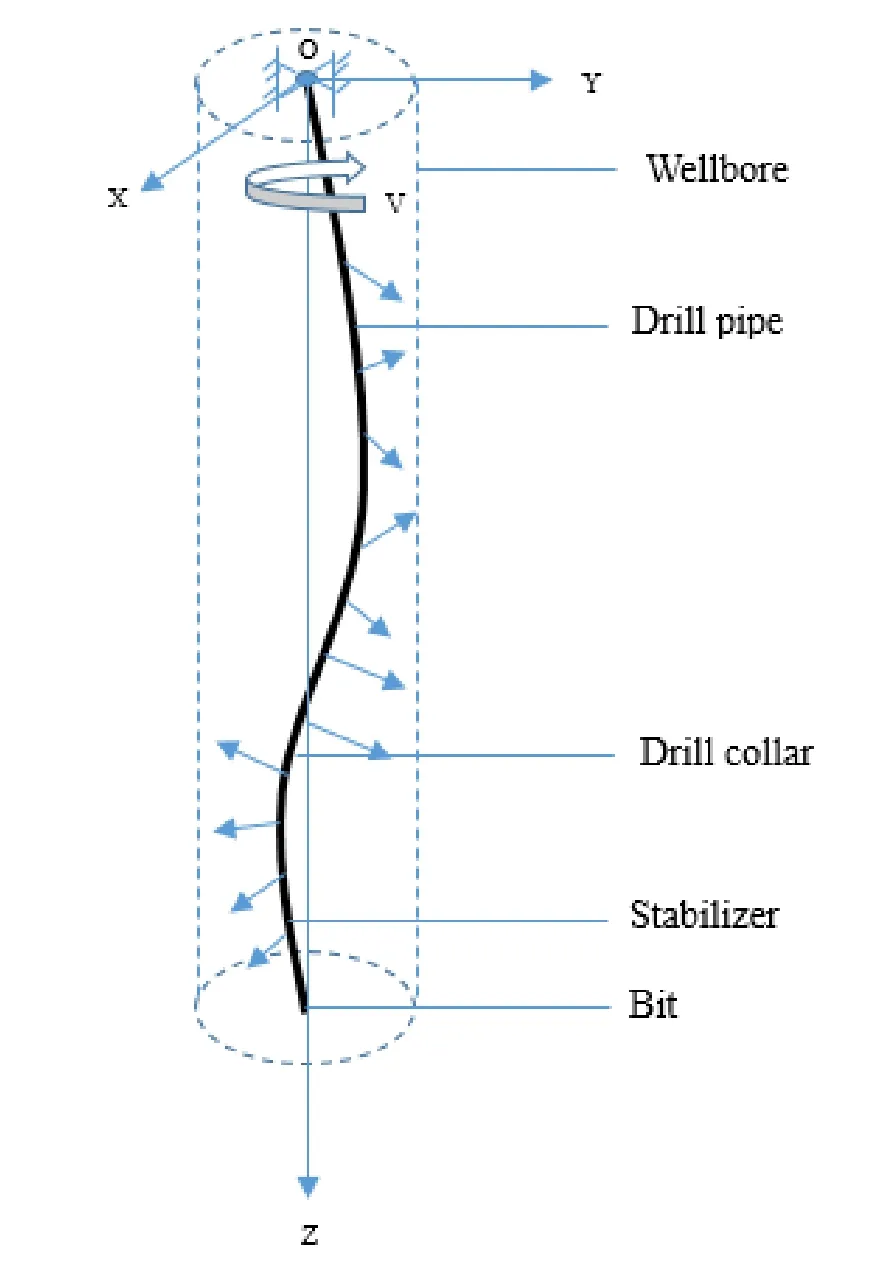
Figure 1:Drillstring vibration system
The forces imposed on the drillstring include the self-weight,hook load,cutting force at the bit,axial force and fluid resistance.The vibration equations of one particle is

where (xi,yi,zi) is the position of particle,i,i-1 and i+1 represents the particle number,miis the equivalent mass of particle i.fiand fi′are the component forces of the external force of particle i in 0-xy plane and z axis,including the gravity and contact force,φ is the angle between the component force fiand x axis,kiand ki-1are the stiffness coefficients,ci-1and ciare the damping coefficients,Fiand Fi-1are the axial forces,γ is the angle between the axial force Fiand z axis,γ′is the angle between the axial force Fi-1and z axis,θ is the angle between the component force of axial forces Fiand x axis,θ′is the angle between the component force of axial forces Fi-1and x axis.
After equations of the total particles programmed in matrix form,the system vibration equation can be cast as


where [J],[K],[C],{U} and {Q(t)} have the following form,

In this work,Rayleigh damping is used to substitute the drilling fluid damping.

where ∂ and β are damping coefficients.
By introducing the boundary constraint and solving the equation of Eq.(2) by the Wilson -θ method of stepwise integration,the dynamic analysis of the entire drillstring system can be completed.
2.2 Numerical model
2.2.1 Basic hypothesis of numerical model
The following assumptions are used in the modeling:(1) The whole well drillstring is a slender beam element,the geometric size and material properties are segmented as constant;(2) Ignore the influence of the connecting thread between the two drill tools on the movement of the drillstring;(3) The initial drillstring axis coincides with the wellbore axis;(4) The borehole wall maintains a circular section,and the influence of collapse of the borehole wall is not considered for the time being;(5) The suspension system is equivalent to a spring with a stiffness of Kℎ.
2.2.2 Numerical simulation analysis method
The finite element software pre-processing module is applied in the analysis,and the 3D beam element BEAM31,the rigid body shell element R3D4 and the hexahedral element C3D8R are respectively meshed.The numerical model is shown in Fig.2.The material parameters,contact pairs and boundary conditions of the finite element model of the drillstring are defined.The fluctuation of WOB is judged by analyzing the axial force in the direction 1 at the bit.The displacement distribution of the drillstring can be obtained by establishing the coordinate system and extracting the displacement values in the three directions of each node in the curved section and horizontal section respectively.In addition,the difference between wellhead torque and bottom-hole torque is the friction torque of the whole drillstring,which represents the torque loss along the drillstring.In the simulation calculation process,a continuous rigid-flexible contact simulation method is adopted between the drillstring and the borehole wall.Once contact occurs,the contact force obtained in the interaction model between the drillstring and the borehole wall is added to the force matrix for subsequent calculation.
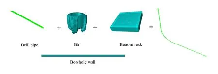
Figure 2:Numerical simulation of shale gas horizontal well dynamics system in Sichuan-Chongqing area
2.3 Experiment calibration
2.3.1 Establishment of experimental bench
In order to verify the conclusions obtained from the simulation model,a drillstring experiment bench for horizontal well is established based on similarity theory,as shown in Fig.3.The actual inner and outer diameter and length of drillstring areD,d,Lrespectively,so the corresponding inner diameter,outer diameter and length of the model drillstring areDm,dm,Lmrespectively.So we have the following equation:

Based on the theory of rotor dynamics,the differential equation of drillstring motion is established:

The model equation can be obtained by substituting the model variables,and the ratio of the model related variables to the corresponding variables of the original equation is set as c,that is:

by replacing the model variable with the original equation variable,the equation of motion with the original variable and the relevant proportional coefficient can be obtained.
Taking the ratio of critical rotation speed of drill string as a measure,the similarity criterion for establishing proportional test bench can be obtained:

The actual drillstring uses S135 steel,E=210 GPa,ρ=7850 Kg/m3,drillstring outside diameter Ø=127 mm,the simulation drillstring using PVC pipe,E = 3.507 Gpa,ρ=1630 Kg/m3,the outer diameter of the body is 13 mm,so:

The experimental speed is 2.77 times of the corresponding field actual speed,and the experimental WOB is 1/5714 of the field actual WOB,that is,when the experimental speed is 110.8 r/min,the WOB 9.56 N is equivalent to the actual field speed of about 40 r/min and WOB 54.6 kN.The comparison between the experimental data and the field data (rotational speed,WOB) is shown in Tab.1.By measuring the values of the load applied end and the bottom hole bit end,the fluctuation of the bottom hole load with the axial load under different WOB and rotational speed is obtained,and then the correctness of the simulation model is verified.The left end of the bench exerts WOB and rotation speed.According to the parameters of borehole trajectory,the height and inclination angle can be adjusted to simulate the curved section with different curvature radius.Fig.4 is drillstring system and data acquisition system.Fig.5 is physical diagram.

Figure 3:Schematic diagram of horizontal well experiment bench

Table 1:Comparison of experimental parameters and field parameters
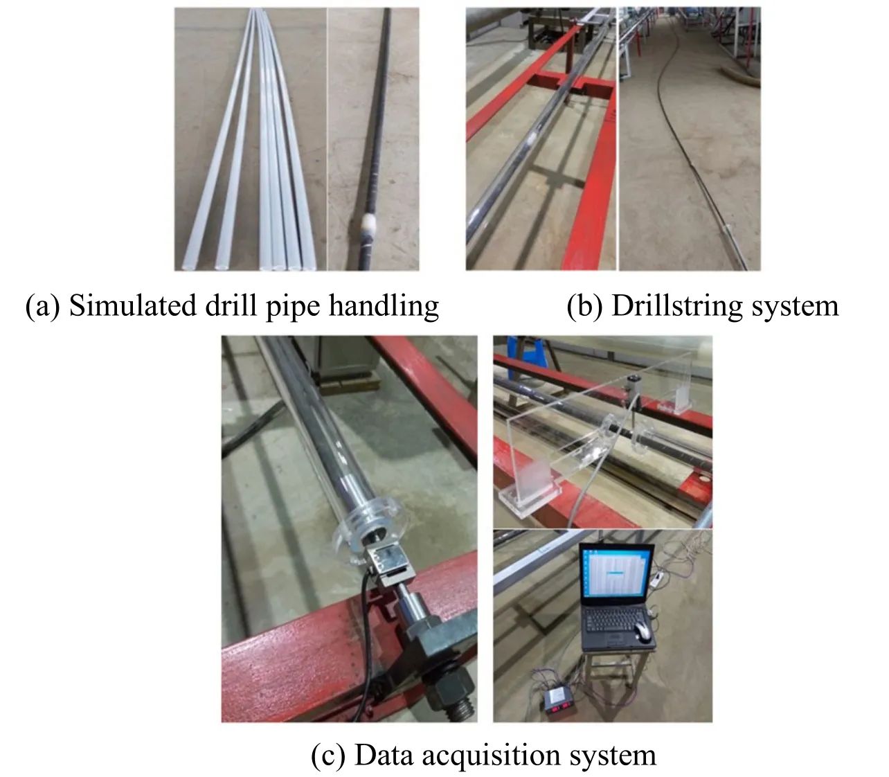
Figure 4:Horizontal well experimental bench details

Figure 5:Horizontal well test bench physical diagram
2.3.2 Experimental method
Adjusting the motor speed and axial load to measure the axial load transfer under different WOB and speed conditions.After loading to different test points (each test point corresponds to a different axial load condition),the load remains stable.At the same time,the measurement of fluctuating load in a period of time is completed.Then,the load is loaded to the next test point until all the tests are completed,and the obtained electrical signals are converted and processed.According to this method,the test sample group is completed under different rotational speed and WOB combination conditions.
2.3.3 Analysis of WOB
Fig.6 is the standard deviation of the load value measured at the bottom,which reflects the fluctuation of the bottom load under different drilling parameters.It can be seen from the figure that the fluctuation amplitude of bottom load increases with the increase of axial load under different rotational speeds;Fig.7 is the simulation result of axial force fluctuation under the condition of different WOB and rotational speed.It can be concluded from the figure that the axial force fluctuation increases with the increase of WOB at different rotating speeds.
The conclusion is consistent with the experimental results,which proves the reliability of the numerical model.
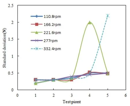
Figure 6:Standard deviation of bottom load under different conditions
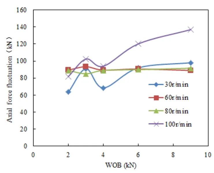
Figure 7:Simulation results of axial force fluctuations under different conditions
2.3.4 Analysis of drillstring bending shape
The rotation speed was adjusted to 322.4 rpm,and the axial load was slowly and uniformly increased to observe the deformation of drillstring at each measuring point.First,the initial horizontal drillstring (3-7 m) connected to the bending section was bent,presenting a sinusoidal buckling in the vertical plane (as shown in Fig.8) with minor lateral vibration.
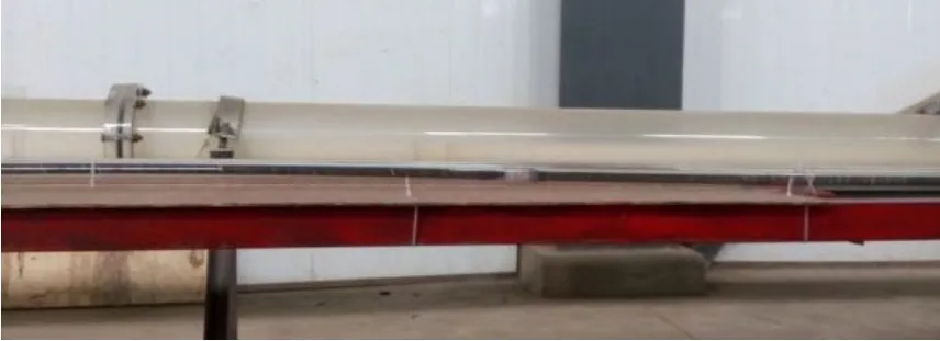
Figure 8:Sinusoidal buckling pattern of drill string within 5-7 m segment
Due to the serious spiral buckling of the drillstring at 12-16 meters (as shown in Fig.9),significant vortexes (forward and reverse) appear in this section and have a great influence on the drillstring at the rear section.The drillstring at 18-19 meters also shows obvious vortexes,while the drillstring at 19-22 meters presents violent axial or lateral vibration.

Figure 9:Spiral buckling pattern of drillstring in section 12-16 m
Fig.10 shows the experimental drillstring deformation patterns under different axial loads at a rotational speed of 322.4 rpm.As can be seen from the figure,when the load is 6.37 N,whirling motion appears within the position range of 14-15 m.With the increase of axial load,except for continuous spiral buckling and whirling,drillstring presents more serious lateral and axial vibration.In the experiment,the percussion sound of drillstring between the borehole wall can be clearly heard,so it can be inferred that the contact force between the drillstring and the borehole wall also increases with the increase of drilling speed and axial load.Fig.11 is the section diagram of borehole wall and drillstring in the simulation analysis.The 2,3 direction is perpendicular to the wellbore axis.With the increase of axial compression force,the bending moment (SM) in the direction of 2 and 3 increases,which indicates that the lateral deformation of drillstring intensifies.The displacement in the vertical direction in Fig.12 also confirms this trend.It can be seen that the lateral displacement at 15m is obviously greater than 5 m and 8 m,indicating that the buckling behavior of drillstring is more severe.

Figure 10:Analysis of drillstring deformation under different load conditions (experiment a:6.37N;b:12.75N;c:19.1N)
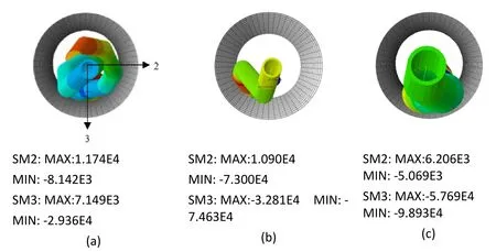
Figure 11:Analysis of drillstring deformation under different load conditions (simulation a:36.4 kN;b:72.8 kN;c:109.1 kN)

Figure 12:(322.4 rpm,19.1N) Time variation of drillstring displacement at 5 m,8 m and 15 m
3 Results and discussions
3.1 Numerical results
In order to obtain the drillstring dynamics of shale gas horizontal wells in Sichuan- Chongqing area,three types of wells are studied,which are XS21-4H medium-shallow horizontal well,a shale gas medium- deep horizontal well in Changning block,Yuanba 272- 1H ultra- deep horizontal well.Reffered to as medium-shallow well 1,medium-deep well 2 and ultra-deep well 3.Fig.13 is the well structure diagram of three horizontal wells.

Figure 13:Horizontal wells structure (a:Medium-shallow well 1 structure;b:Mediumdeep well 2;c:Ultra-deep well 3)
3.1.1 Basic data
The simulation drilling tool assembly of three wells is as follows:Ø311 mm/Ø215.9 mm PDC
bit+Stabilizer×1.5 m+Ø158 mmDrillcollar×9 m+HWDP×30 m+Ø127 mmDrillpipe+Ø158 mm Drill collar×18 m
The parameters of the drillstring used in the simulation are given in Tab.2.

Table 2:Horizontal well simulation calculation parameters
3.1.2 Analysis of numerical results
1.WOB
The WOB is derived from the self-weight of BHA and is the result of the interaction between the bit and rock.The fluctuation of WOB is the main factor affecting the severity of the axial vibration of the drillstring.Figs.14-16 are time history curves of the dynamic WOB response of three case wells.As can be seen from the figure:
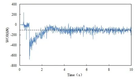
Figure 14:Time history curve of dynamic response of WOB in medium-shallow well 1
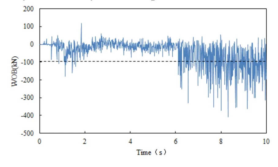
Figure 15:Time history curve of dynamic response of WOB in medium-deep well 2
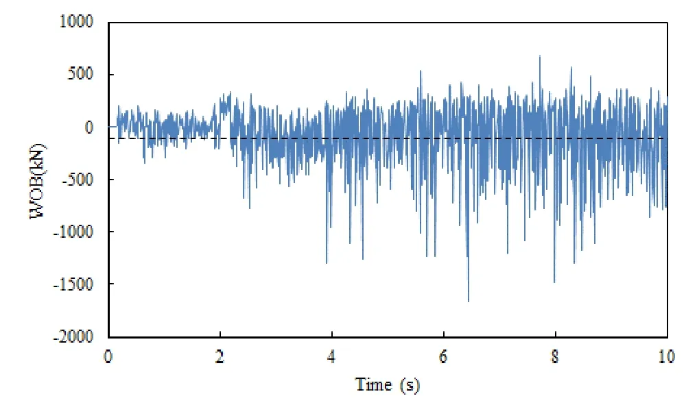
Figure 16:Time history curve of dynamic response of WOB in ultra-deep well 3
The average fluctuation range of the WOB in the medium-shallow well 1 is about 20% to 50% of the static WOB;the maximum instantaneous WOB is (150-300)×103N,which is about 1.5 to 3 times of the static WOB (Fig.14);The average fluctuation range of the WOB in the medium-deep well 2 is about 20% to 70% of the static WOB,which is twice that of the medium-shallow well 1;the maximum instantaneous WOB is (200-400)×103N,which is about 2~4 times of the static WOB,1.3 times that of the medium-shallow well 1 (Fig.15);The average fluctuation range of the WOB in the ultra-deep 3 well is about 50% to 400% of the static WOB,which is 8 times that of the medium-shallow well 1.The maximum instantaneous WOB is (500~1700)×103N,which is about 5 to 10 times of the static WOB,which is 3.3 times that of the medium-shallow well 1 (Fig.16).
Dynamic WOB simulation results show that the depth of ultra-deep well 3 is only 1.27 times of that of medium-deep well 2,but the fluctuation of WOB is 2.8 times.It is shown that the increase of well depth in a small range will bring about a large increase in the fluctuation of WOB.In addition,at some critical values,the drillstring may lose stability,buckling and begin to perform wave bending vibrations,which hinder the transmission of torque and axial forces,resulting in fatigue damage to the entire structure,its wear,wellbore damage and reduce the efficiency of the drilling process [Gulyaevl and Glazunov (2017)].
2.Axial force distribution of the drillstring
The fluctuation of axial force can characterize the axial vibration of the drillstring at different locations in the wellbore,which is of great significance for evaluating the quality of drilling parameters.Figs.17-19 are axial force distribution diagrams of drillstrings of three example wells.As can be seen from the figure:
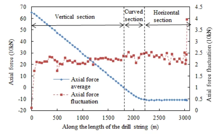
Figure 17:Axial force distribution of drillstring in medium-shallow well 1
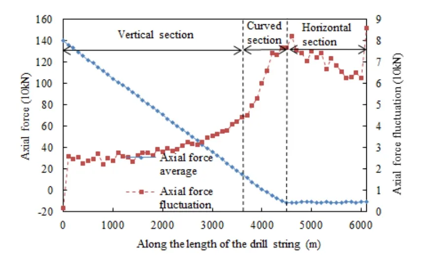
Figure 18:Axial force distribution of drillstring in medium-deep well 2

Figure 19:Axial force distribution of drillstring in ultra-deep well 3
The neutral point of the medium-shallow well 1 is located near the depth of 1800 m,and the axial force fluctuation amplitude of the drillstring above and below the neutral point is small.The fluctuation amplitude on the bit is 25 kN,which is 25% of the average force at this point (Fig.17);The neutral point of the medium-deep well 2 is located near the depth of 4000 m.The fluctuation amplitude is smaller above the neutralization point,and increases greatly below the neutralization point.The fluctuation amplitude in the horizontal section is maintained at about 75 kN and reaches 90 kN on the drill pipe near the bit,which is 90% of the average force at the bit.(Fig.18);The neutral point of the ultra-deep well 3 is located near the depth of 6000 m.The fluctuation amplitude is always in an increasing state,reaching 250 kN near the bit,which is 2.5 times the average force;The maximum increase below the neutral point is 250 kN on the drill pipe near the bit,which is 2.5 times of the average force at this point (Fig.19).
The calculation results of drillstring axial force distribution show that,compared with medium-shallow wells,medium-deep wells and ultra-deep wells are subject to higher fluctuations amplitude at the end of curved section and horizontal section,especially in ultradeep wells,the fluctuation in the whole horizontal section is about 2 times of the WOB.The reason is that the friction of the ultra-deep well increases gradually in the horizontal section,and the spiral buckling occurs frequently,which leads to serious rubbing between the drillstring and the wellbore.The violent axial force fluctuation is the root cause of the failure of the BHA,which easily enlarges the crack of the drill pipe,reduces the fatigue life and causes fatigue damage.During drilling,accurate axial loads are provided for reliable drillstring strength design or strength check to determine construction action risks.
3.Drillstring lateral displacement distribution
The fluctuation amplitude of drillstring lateral displacement represents the intensity of lateral vibration.Fig.20 shows the displacement diagram of three well bits in the 1 and 2 directions (two directions perpendicular to the borehole axis).The displacement fluctuation amplitude is 9.79 mm,1.09 mm and 4.96 mm in direction 1,respectively,and with a 8.17 mm,4.87 mm and 3.03 mm in direction 2,respectively.The lateral displacement fluctuation indicates that the lateral vibration has a decreasing trend with the increase of the depth.
Fig.21 is a displacement coupling diagram of the bit,which can be obtained from the diagram:The bit of the medium-shallow well 1 are displaced in all four quadrants and are at the low side of the wellbore for most of the time (Fig.21(a));The bit of the mediumdeep well 2 and ultra-deep well 3 deviate from the axis of the wellbore (Figs.21(b),21(c)).The displacement coupling diagram of the bit indicates that the bit deviates from the center of the borehole as the well depth increases.Because of the pulling effect of gravity,the drillstring is almost close to the low side of the wellbore from the end of the curved section.In addition,due to the high friction at the horizontal section,sinusoidal buckling and spiral buckling frequently occur in the BHA,causing the drillstring to deviate from the center of the well and thus the bit to deviate from the center of the borehole.

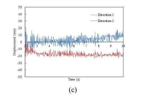
Figure 20:Bit displacement in 1 and 2 directions (local coordinates) (a.medium-shallow well 1;b.medium-deep well 2;c.ultra-deep well 3)
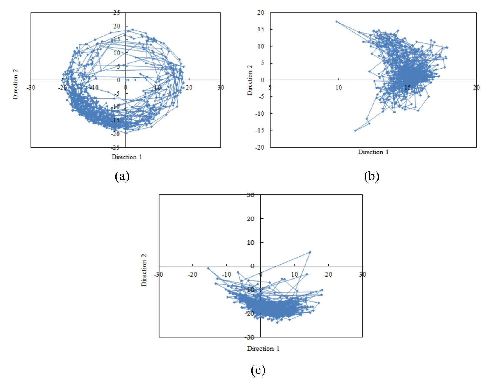
Figure 21:Bit lateral displacement coupling diagram (a:medium-shallow well 1;b:medium-deep well 2;c:ultra-deep well 3)
4.The friction torque
Discussion of friction torque for torsional vibration research has more practical significance in the field.Fig.22-Fig.24 are time-history diagrams of friction torque,which can be seen from the figure:The friction torque in the medium-shallow well 1 varies widely,the fluctuation amplitude is 2.18 kN∙m,and the average value is 3.87 kN∙m (Fig.22).The
medium-deep well 2 has a small friction torque at 2-9 s,and the friction torque increases significantly and then decreases at 9-9.5 s.The maximum friction torque is about 12 kN∙m,the average value is 4.53 kN∙m,and the fluctuation amplitude is 2.56 kN∙m (Fig.23).The transient maximum value of the friction torque of the ultra-deep well 3 is 20 kN∙m,the average value is 6.84 kN∙m,and the fluctuation amplitude is 4.67 kN∙m (Fig.24).
The results show that the transient maximum value,average value and fluctuation amplitude of the friction torque increase with the increase of the well depth.When the friction value is close to the rated torque value of the equipment,the long-term operation will increase the temperature of the drilling equipment,and in severe cases,the drilling equipment may be damaged [Zhu,Li and Liu (2015)].There are many factors influencing friction torque,such as well structure,BHA,drilling parameters,etc.It will be studied in detail in Section 3.2 and not discussed much here.

Figure 22:Time history curve of friction torque in medium-shallow well 1
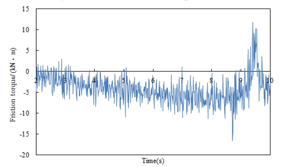
Figure 23:Time history curve of friction torque in medium-deep well 2
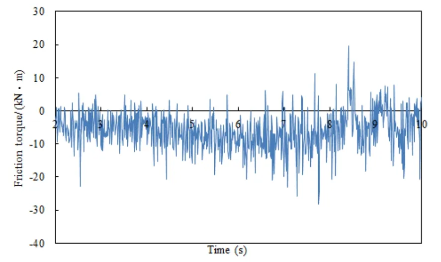
Figure 24:Time history curve of friction torque in ultra-deep well 3
3.2 Discussion on the influence degree of well structure,drilling parameters,BHA on vibration characteristics of drillstring
Firstly,medium-shallow well 1 are used as the research model.The degree of influence on the vibration characteristics of the drillstring is discussed by changing the well structure,BHA and drilling parameters.
3.2.1 Influence on WOB

Figure 25:Effect of parameter change on WOB (a:Horizontal length;b:Vertical length;c:Number of drll collars;d:Rotating speed)
3.2.2 Influence on drilling resistance torque
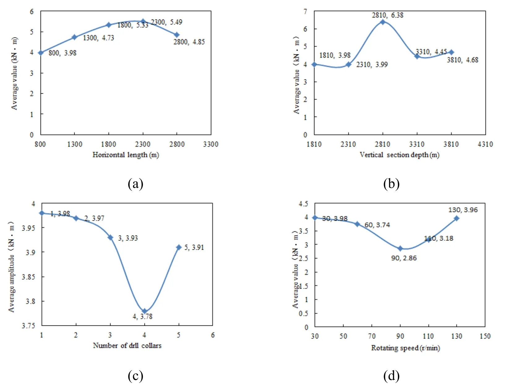
Figure 26:Effect of parameter change on friction torque (a:Horizontal length;b:Vertical length;c:Number of drll collars;d:Rotating speed)
The change rate obtained from 3.2.1-3.2.2 is listed as follows:

Table 3:Influence of parameter variation on WOB and Friction torque
It can be seen from Tab.3:(1) The change of vertical depth is the most important factor,and the change of horizontal length is the secondary factor,which leads to the great difference of the fluctuation of dynamic WOB in the three wells.The deeper the vertical section is,the greater the fluctuation of WOB is.Therefore,it is suggested to increase stabilizers or downhole dynamic drilling tools to reduce the fluctuation of WOB and improve the rock-breaking efficiency in drilling operations.(2) The change of vertical depth is the main factor that causes the difference of friction torque among three case wells,and the change of rotational speed is the secondary factor.It is suggested to improve the borehole quality or install friction-reducing joints to reduce friction torque.
3.3 Discussion on reasonable speed of three wells
By changing the rotational speed,the influence of the rotational speed on the dynamic WOB and the friction torque of three wells is obtained,then the reasonable rotational speed range is optimized.
3.3.1 Effect on dynamic WOB
It can be seen from Fig.27 that the reasonable rotation speeds of the three wells are:The speed of the medium-shallow well 1 is 90-130 r/min;The low speed of the medium-deep well 2 is 30~60 r/min,high speed choose110-130 r/min;Ultra-deep well 3 low speed selection 60 r/min,high speed selection 110-130 r/min.
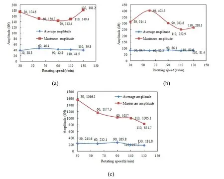
Figure 27:Effect of speed change on WOB of three wells (a:medium-shallow well 1;b:medium-deep well 2;c:ultra-deep well 3)
3.3.2 Influence on drilling resistance torque

Figure 28:Effect of speed change on friction torque of three wells (a:medium-shallow well 1;b:medium-deep well 2;c:ultra-deep well 3)
As can be seen from Fig.28:The low speed selection of the medium-shallow well 1 is 30-60 r/min,the high speed selection is 90 r/min;The low speed selection of the medium-deep well 2 is 30-60 r/min,high speed selection 130 r/min;ultra-deep well 3 low speed selection 90r/min,high speed selection 130 r/min.
Through the discussion of 3.3.1-3.3.2,the reasonable speed can be list as Tab.4:

Table 4:Summary of reasonable rotating speed
3.4 Engineering application
3.4.1 Prediction of fatigue life
In recent years,domestic scholars have made statistical analysis of drillstring failure cases and found that more than 80% of drillstring fracture failures are fatigue failures or related to fatigue [Wu,Chen,Zhu et al.(2012)].In view of the fact that the horizontal wells will be deeper in the future,the fatigue prediction of the ultra-deep well 3 drillstring and the location of the dangerous points are of great significance for the failure warning.
Based on the function expression of S-N curve (9),the fatigue life of drillstring can be obtained by calculating the working stress amplitude through the dynamic calculation [Lin,Zou,Zhang et al.(2004)].

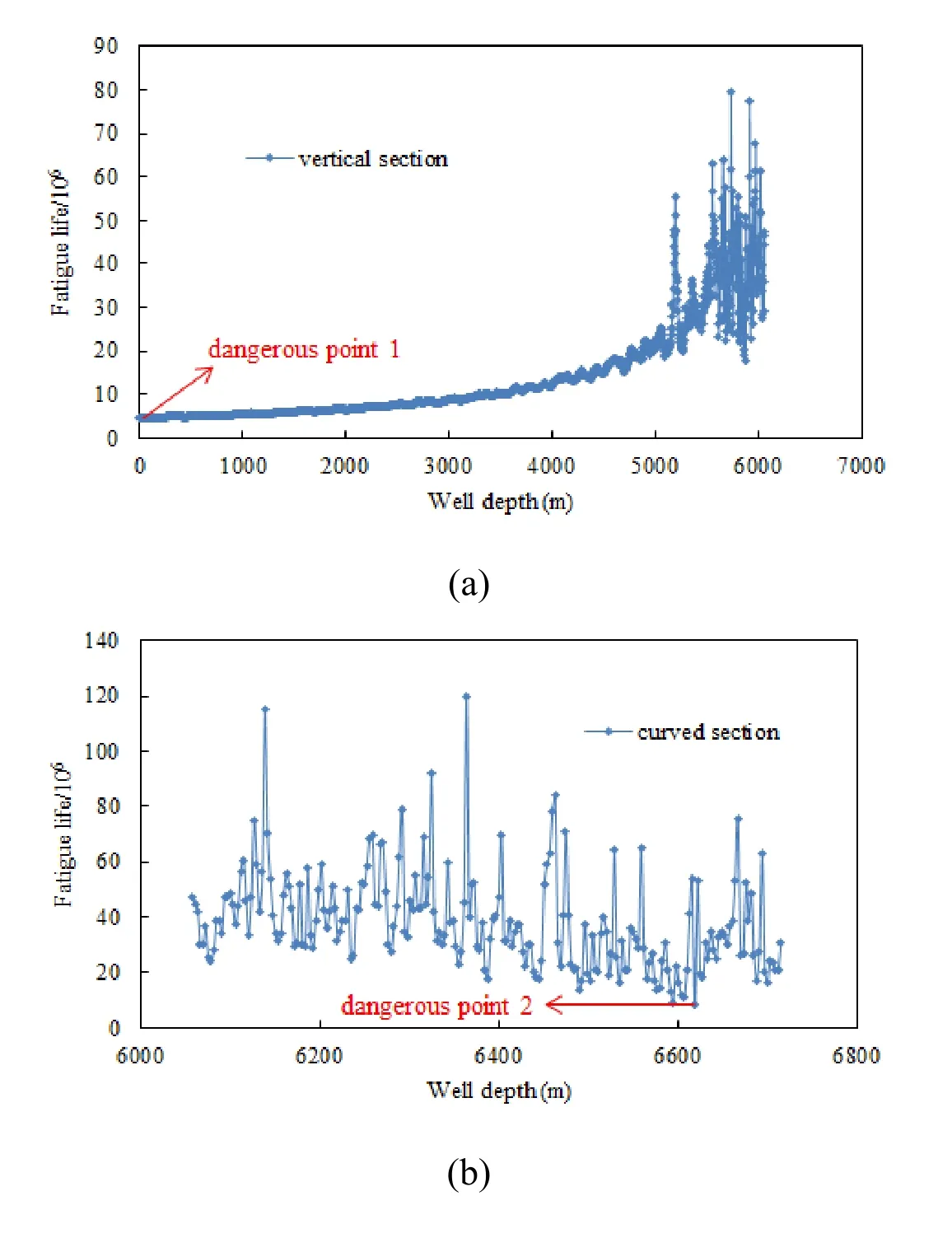

Figure 29:Fatigue life of drillstring in different sections (a:Vertical section;b:Curved section;c:Horizontal section)
Fig.29 shows the fatigue life of different sections of ultra-deep well 3,as can be seen from the figure:The fatigue life of the drillstring at the wellhead is very small because the drillstring is pulled by the gravity of the whole drillstring and the safety factor is the lowest;According to field statistics,the wellhead failure is also serious,this is the danger point 1;The fatigue life of the drillstring in the curved section varies greatly due to the alternating stress of the drillstring.Especially at the end of the curved section,due to the increase of inclination angle,the bending of the drillstring is serious and the fatigue life of the drillstring is low.The dangerous point 2 appears at 6618 m;Sinusoidal buckling and spiral buckling occur frequently in the horizontal section of the drillstring,the friction between the drillstring and the wellbore is serious and the fatigue life is low.The dangerous point 3 appears at 7200 m.
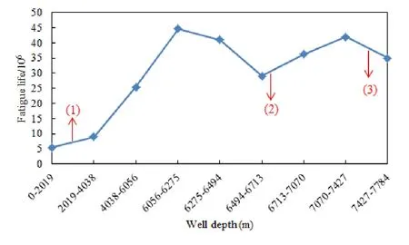
Figure 30:Average fatigue life of drillstring in different sections
Fig.30 shows the average fatigue life of drillstring in different sections.From the diagram,we can get the sections with lower fatigue life,which are the upper part of vertical section (0 m-2019 m),the end of curved section (6713 m-7070 m) and the end of horizontal section (7427 m-7784 m) (as shown (1)~(3)).Combined with Fig.29,we can draw the following conclusions:the fatigue life of drillstring in ultra-deep well 3 is very low at the wellhead position,the end of curved section and the end of horizontal section,which is the most likely to occur drillstring failure.Therefore,great attention should be paid to the actual drilling in the field.
3.4.2 Rotating speed application
The reasonable speed of the three typical wells obtained in Section 3.3 of this paper have been applied in drilling engineering.For example,in the statistics table of drilling parameters of XC gas reservoir in western Sichuan,it is pointed out that the rotation speed is 50-80 r/min;In the actual drilling of a well in Jiangdong Fuling area,the drilling parameters are 40~50 r/min;In Dagang in a long horizontal well of the oilfield,the speed is selected from 120 r/min to 130 r/min;In an oilfield KS ultra-deep horizontal well,the speed is shown in Fig.27 (red indicates danger,yellow indicates warning,green indicates safety).Under 100kN WOB,it is necessary to avoid 150 r/min.The actual application in the field shows that the speed selection obtained by the numerical model is reasonable.
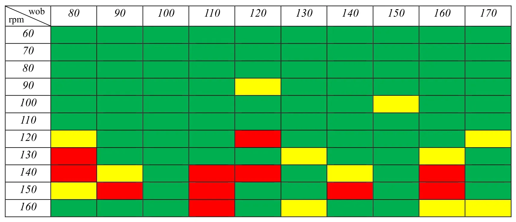
Figure 31:Distribution of drilling speed and WOB in actual drilling
4 Conclusion
A finite element dynamical model was established for characterizing drillstring threedimensional coupled vibration in shale gas horizontal wells.To verify the numerical simulation,an indoor drillstring experimental apparatus was built based on the similarity criterion.The three-dimensional coupled vibration characteristics of drillstring in different wells were analyzed and some useful conclusions and suggestions were obtained:
1.The experimental results on WOB and drillstring deformation form are consistent with the simulation results,and the simulation numerical model can be used to study the drillstring dynamics of horizontal wells.
2.Dynamic WOB simulation results show that the depth of ultra-deep well 3 is only 1.27 times of that of medium-deep well 2,but the fluctuation of WOB is 2.8 times.The fundamental reason is that the change of vertical section length is the most important factor affecting WOB fluctuation.The deeper the vertical depth is,the greater the fluctuation of WOB is.Excessive WOB fluctuation will lead to violent axial vibration,which will seriously affect rate of penetration.
3.Compared with medium-shallow wells,medium-deep wells and ultra-deep wells are subject to higher axial force fluctuations value at the end of curved section and horizontal section,especially in ultra-deep wells,the fluctuation in the whole horizontal section is about 2 times of the WOB.The reason is that the friction of the ultra-deep well increases gradually in the horizontal section,and the spiral buckling occurs frequently,which leads to serious rubbing between the drillstring and the borehole.
4.The change of vertical depth is the main factor that causes the difference of friction torque among three example wells,and the change of rotational speed is the secondary factor.It is suggested to improve the borehole quality or install friction-reducing joints to reduce friction torque.
5.For Medium-shallow horizontal wells,low speed drilling is selected from 30 to 50 r/min (avoiding 60 r/min),high speed drilling is selected at 90 r/min;for Medium-deep horizontal wells,low speed drilling is selected from 30 to 50 r/min,high speed drilling selection is 90-130 r/min;for Ultra-deep horizontal wells,low-speed drilling is 30-50 r/min,and highspeed drilling is 90-130 r/min,this conclusion has been applied in the field.
6.The fatigue life of ultra-deep drillstring at the wellhead position,the end of curved section and the end of horizontal section is very low,and stress danger points appear in all three sections,which is prone to drillstring failure.Therefore,special attention should be paid to these three areas in the project.
Conflicts of Interest:The authors declare that they have no confilcts of interest.
Acknowledgment:This research is supported by the Natural Science Fund (Grant No.51674214),Youth Scientific Research Innovation Team Project of Sichuan Province (2017TD0014),International Cooperation Project of Sichuan Science and Technology plan (2016HH0008).
References
Chen,S.L.;Ren,F.S.(2017):Vibration analysis of horizontal rotating beam in pipe.International Journal of Hydrogen Energy,vol.42,pp.18741-18746.
Chen,Y.;Fu,J.;Ma,T.;Tong,A.;Guo,Z.et al.(2018):Numerical modeling of dynamic behavior and steering ability of a bottom hole assembly with a bent-housing positive displacement motor under rotary drilling conditions.Energies,vol.11,pp.1-23.
Feng,T.;Vadali,M.;Ma,Z.;Chen,D.;Dykstra,J.(2017):A finite element method with full bit-force modeling to analyze drillstring vibration.Journal of Dynamic Systems,Measurement,and Control,vol.139,no.091016,pp.1-10.
Germay,C.;Van de Wouw,N.;Nijmeijer,H.;Sepulchre,R.(2009):Nonlinear drillstring dynamics analysis.Siam Journal on Applied Dynamical Systems,vol.8,no.2,pp.527-553.
Ghasemloonia,A.;Geoff Rideout,D.;Butt,S.D.(2013):Vibration analysis of a drillstring in vibration-assisted rotary drilling:finite element modeling with analytical validation.Journal of Energy Resources Technology,vol.135,no.032902,pp.1-17.
Gulyayev,V.I.;Gaidaichuk,V.V.;Solovjov,I.L.;Gorbunovich,I.V.(2009):The buckling of elongated rotating drillstrings.Journal of Petroleum Science and Engineering,vol.67,no.3-4,pp.140-148.
Gulyaevl,V.I.;Glazunov,S.N.(2017):Stability and vibrations of rotating drillstring in a horizontal wellbore.Strength of Materials,vol,49,no.6,pp.769-777.
Kapitaniak,M.;Hamaneh,V.V.;Chávez,J.P.;Nandakumar,K.;Wiercigroch,M.(2015):Unveiling complexity of drill-string vibrations:experiments and modeling.International Journal of Mechanical Sciences,vol.101,pp.324-337.
Khulief,Y.A.;Al-Naser,H.(2005):Finite element dynamic analysis of drillstrings.Finite Elements in Analysis and Design,vol.41,pp.1270-1288.
Leine,R.I.;Van Campen,D.H.;Keultjes,W.J.G.(2002):Stick-slip whirl interaction in drillstring dynamics.Journal of Vibration and Acoustics,vol.124,no.2,pp.209-220.
Lin,Y.H.;Zou,B.;Zhang,J.B.;Shi,T.H.(2004):Predicting fatigue life in consideration of drill stem movement behaviours.Natural Gas Industry,vol.5,pp.57-60.
Liu,Y.S.;Gao,D.L.(2017):A nonlinear dynamic model for characterizing downhole motions of drill-string in a deviated well.Journal of Natual Gas Science and Engineering,vol.38,pp.466-474.
Ojanomare,C.;Cornetti,P.;Romagnoli,R.;Surace,C.(2017):Fatigue crack growth analysis of drill pipes during rotary drilling operations by the multiple reference state weight function approach.Engineering Failure Analysis,vol.74,pp.11-34.
Qiu,H.;Yang,J.;Butt,S.;Zhong,J.(2017):Investigation on random vibration of a drillstring.Journal of Sound and Vibration,vol.406,pp.74-88.
Richard,T.;Germay,C.;Detournay,E.(2007):A simplified model to explore the root cause of stick-slip vibrations in drilling systems with drag bits.Journal of Sound and Vibration,vol.305,no.3,pp.432-456.
Sahebkar,S.M.;Ghazavi,M.R.;Khadem,S.E.;Ghayesh,M.H.(2011):Nonlinear vibration analysis of an axially moving drillstring system with time dependent axial load and axial velocity in inclined well.Mechanism and Machine Theory,vol.46,pp.743-760.
Sarker,M.;Rideout,D.G.;Butt,S.D.(2017):Dynamic model for 3D motions of a horizontal oilwell BHA with wellbore stick-slip whirl interaction.Journal of Petroleum Science and Engineering,vol.157,pp.482-506.
Tian,J.;Yang,Y.;Yang,L.(2017):Vibration characteristics analysis and experimental study of horizontal drill string with wellbore random friction force.Archive of Applied Mechanics,vol.87,pp.1439-1451.
Trindade,M.A.;Wolter,C.;Sampaio,R.(2005):Decomposition of coupled axialbending vibrations of beams subject to impacts.Journal of Sound and Vibration,vol.279,pp.1015-1036.
Wang,B.;Ren,F.;Yao,Z.;Fang,T.(2019):Mathematical model and experimental investigation of bit-bounce in horizontal oil well drillstring.Arabian Journal for Science and Engineering,vol.44,pp.8095-8111.
Wu,L.X.;Chen,P.;Zhu,X.H.;Zhang,W.H.;Jia,Y.J.et al.(2012):Contrast of fatigue failure cycles of drill string during gas drilling.Petroleum Drilling Techniques,vol.40,no.1,pp.42-46.
Wu,X.(2019):Key technologies for evaluation and development of high productivity zone in Weiyuan Shale Gas Field.Petroleum Drilling Techniques,vol.47,pp.1-11.
Yigit,A.S.;Christoforou,A.P.(1998):Coupled torsional and bending vibrations of drillstrings subject to impact with friction.Journal of Sound and Vibration,vol.215,no.1,pp.167-181.
Zamanian,M.;Khadem,S.E.;Ghazavi,M.R.(2007):Stick-slip oscillations of drag bits by considering damping of drilling mud and active damping system.Journal of Petroleum Science and Engineering,vol.59,pp.289-299.
Zhu,X.H.;Jia,Y.J.;Tong,H.(2012):Vibrating characteristics of drillstring in gas drilling and its control measures.Acta Petrolei Sinica,vol.33,no.2,pp.293-297.
Zhu,X.H.;Li,B.(2019):Numerical simulation of dynamic buckling response considering lateral vibration behaviors in drillstring.Journal of Petroleum Science and Engineering,vol.173,pp.770-780.
Zhu,X.H.;Li,B.;Liu,Q.Y.;Chang,X.J.;Li,L.C.et al.(2015):New analysis theory and method for drag and torque based on full-hole system dynamics in highly deviated well.Mathematical Problems in Engineering,vol.2015,pp.1-13.
 Computer Modeling In Engineering&Sciences2019年11期
- Computer Modeling In Engineering&Sciences的其它文章
- IDSH:An Improved Deep Su pervised Hashing Method for Image Retrieval
- Numerical Simulations of the Ice Load of a Ship Navigating in Level Ice Using Peridynamics
- Research on Nonlinear Frequency Compression Method of Hearing Aid with Adaptive Compression Ratio
- Feature Selection with a Local Search Strategy Based on theForest Optimization Algorithm
- Some Remarks on the Method of Fundamental Solutions for Two-Dimensional Elasticity
- A Parametric Study of Mesh Free Interpolation Based Recovery Techniques in Finite Element Elastic Analysis
