Synchronization of Robot Manipulators Actuated By Induction Motors with Velocity Estimator
Felipe J.Torres,Gerardo V.Guerrero,Carlos D.García,Ricardo Zavala-Yoe,Mario A.García and Adolfo R.López
1University of Guanajuato,Division of Engineering Campus Irapuato-Salamanca,Carretera Salamanca-Valle de Santiago km 3.5+1.8,Guanajuato,Salamanca,36885,México.
2National Technological of Mexico/National Center of Research and Technological Development,Av.Palmira S/N colonia Palmira,Morelos,Cuernavaca,62490,México.
3School of Engineering and Sciences,Monterrey Technological,Puente 222 Ejidos de Huipulco,Ciudad de México,14380,México.
4Superior Technological Institute of Irapuato,Carretera Irapuato-Silao km 12.5,Guanajuato,Irapuato,36821,México.
Abstract:A complete modeling(including the actuator dynamics)of a robot manipulator that uses three-phase induction motors is presented in this paper.A control scheme is designed to synchronize robot manipulators actuated by induction motors under a masterslave scheme in the case where the joint velocity of the slave robots is estimated.All of the research on the synchronization of robot manipulators assumes the use of ideal actuators to drive the joints;for that reason,in this work,a three-phase induction motor is considered to be a direct-drive actuator for each joint.An entire model of the mated system is obtained by a combination of the dynamics of the induction motor and robot manipulator.Thus,the synchronization control algorithm for a master-slave scheme in both the joint space and workspace of robot manipulators driven by induction motors is developed.An observer based on the entire model is proposed to estimate the joint velocity of the slave robot manipulators.Through the Lyapunov criterion,a stability analysis of the synchronization control with a velocity estimator is detailed.The analytical results show the synchronization and estimation errors are globally,uniformly,and ultimately bounded.Simulations with multiple robots demonstrate the performance of the proposed control algorithm.
Keywords:Synchronization,robot manipulator,induction motor,Lyapunov stability,observer based on the model.
1 Introduction
The controlled synchronization of robot manipulators has become a subject of interest within the scientifci community during the last decade,mainly because of the effciiency and quality requirements in the production processes,in addition to the flexibility and maneuverability in the execution of tasks that a single robot cannot perform.This has led to the demand that two or more robots complete the same activity in a synchronized manner.This synchronization consists of matching two or more dynamic systems developing singly on a common trajectory from a certain instant onward,one of them called the master and the others the slaves.
In the literature,diverse algorithms of synchronization control have been stated,and all of these works assume ideal actuators.Thus,Nijmeijer et al.[Nijmeijer and Rodriguez-Angeles(2003)]applied a feedback control with access only to the robot’s position.Chung et al.[Chung and Slotine(2009)],from contraction analysis,tracked a common trajectory while maintaining a formation through a directed graph of interconnection.Chopra et al.[Chopra and Spong (2008)] solved the previous features combined with constant delays of communications by using a passivity analysis.Abdessameud et al.[Abdessameud,Polushin and Tayebi(2014)]and Cicek et al.[Cicek and Dasdemir(2018)]used a passivity theorem to consider varying delays.Nuno et al.[Nuño,Ortega,Jayawardhana et al.(2013)]considered the interconnection in the synchronization scheme as a non-directed graph.
Regarding the synchronization problems,different control algorithms have been applied;for instance,Zhang et al.[Zhang,Wang and Guo(2014)]required backstepping;Bouaziz et al.[Bouaziz,Bouteraa and Medhaffar (2013)] made use of cross-coupling;Mei et al.[Mei,Ren and Ma (2011)] used sliding mode controllers;and Chen et al.[Chen and Lewis(2011)]and Cui et al.[Cui and Yan(2012)]achieved synchronization through neural networks(NNs).
Moreover,synchronization approaches in the workspace have been reported.In the study by Kyrkjebo et al.[Kyrkjebo and Pettersen (2007)],in which a virtual manipulator to synchronize robot manipulators in a leader-follower scheme was used,the leader velocity was unknown.Liu et al.[Liu and Chopra (2012)] obtained the synchronization of heterogeneous robot manipulators with varying delays using the passivity property.Wang[Wang(2013)]synchronized robot manipulators without a leader,but rather used directed graphs strongly connected to develop an adaptable control law with attention to parametric uncertainties.Aldana et al.[Aldana,Nuño,Basañez et al.(2014)] synchronized the position and orientation of the robot manipulators:The position synchronization was designed with the use of the Jacobian,while the orientation was synchronized by means of the quaternions.Cicek et al.[Cicek,Dasdemir and Zergeroglu (2015)] synchronized the end effectors of robot manipulators in both the joint space and workspace,considering the parametric uncertainties.
In practice,a great number of industrial robot manipulators use electric motors as actuators,where the DC-brushless permanent magnet(PMBLDC)servomotors are the most common.The advantage of PMBLDC motors is given by their relative ease control of the position and desired trajectory;however,their main disadvantage is cost,which is due to the use of rare earths (neodymium-iron-boron or samarium-cobalt) in the manufacturing process of the permanent magnet and,furthermore,by the necessity of periodic mechanical maintenance.For this reason,an alternative to the use of servomotors is set by employing induction motors (IMs) as actuators.These devices generate a high-output torque and have a low manufacturing cost;furthermore,they are robust and can operate in any environmental conditions,while their disadvantage lies in their control difficulty,which is caused by their high non-linearity.Owing to this fact,Guerrero et al.[Guerrero-Ramírez and Tang(2001)]and Diniz et al.[de Diniz,Júnior,Honório et al.(2012)] researched robot manipulators driven by IMs only to track the desired trajectory.
A synchronization approach that considers ideal conditions in the joint space was addressed in Torres et al.[Torres,Guerrero,Garcia et al.(2016)],where robot manipulators are driven by IMs,and,consequently,the IMs were synchronized in the task execution as well.In this sense,Sun et al.[Sun,Gong,Yang et al.(2019)] synchronized multiple induction motors for a tracking system.In this work,the definition of the tracking error in relation to the angular velocity was considered.Therefore,it was necessary to avoid the chattering phenomena that might be depicted by noise in the velocity and acceleration measurements,leading to other problems in synchronization.
The objective of this work is to develop a master-slave synchronization control scheme for both the joint space and workspace of robot manipulators directly driven by IMs(designated as IM-Robot),considering the load torque for the IMs as the torque derived from the synchronization controller.Hence,the angular positionsqi(t)∈Rn,as well as the position and orientationχi(t)∈Rmof theith slave IM-Robot are synchronized with respect toqj(t)∈Rnandχj(t)∈Rmof the master IM-Robot through the synchronization control approaches based on velocity observer,for the case in which only the angular position measurement of the joints of the slave IM-Robot is available.
The rest of this paper is organized as follows.Dynamic models of the robot manipulator and induction motor are presented in Section 2.In Section 3,the combination of IM dynamics and robot manipulator dynamics is depicted.In Section 4,the synchronization control designs with a velocity estimator in both the joint space and workspace are developed,and in Section 5,the results of the simulations are shown.Finally,conclusions are given in Section 6.
2 Dynamic models
2.1 Dynamic model of a robot manipulator
Considerprobot manipulators fully actuated in which the friction losses are neglected,withk=1,2,···,njoints.The vector of the angular position of the robot joints isqi(t)∈Rn,i= 1,2,···,p.Using the Euler-Lagrange formalism,the dynamic model of theith robot is given by Behal et al.[Behal,Dixon,Dawson et al.(2009)]:

where M(q)∈Rn×nis the inertia matrix,C(q,)∈Rn×nthe Coriolis and centrifugal forces matrix,g(q)∈Rnthe vector of gravitational forces,andτ(t)∈Rnthe vector of input torques.This model comprises the following properties:
1.The inertia matrix M(q)∈Rn×nis symmetric and positive defniite for allqi ∈Rn.
The position and orientation in the workspace of the end-effector of theith robot manipulator are denoted byχi(t)∈Rmthrough Cartesian coordinates:

wheref(·)∈Rmis a nonlinear function of the direct kinematics.
The relationships between the joint velocitiesi ∈Rnand the time derivative of the endeffector coordinates of the robot∈Rmin the workspace are given by

whereJac ∈Rm×nrepresents the Jacobian of the manipulator,defnied as

The pseudo-inverse ofJac ∈Rm×n,described byJac+∈Rn×m,is defnied as

2.2 Dynamic model of IM
The vectors of the currentsiα -iβand flowsλα -λβof the stationary reference frame fxied to the statorα-βof the IM are used to express the equations in a feild-oriented framed-q.In this sense,the model of the IM mechanical and electrical dynamics without consideration of the effects of viscous friction is given by [Marino,Tomei and Verrelli(2010)]:
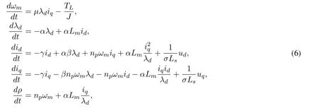

Substitution of Eq.(7)into Eq.(6)results in the closed-loop system
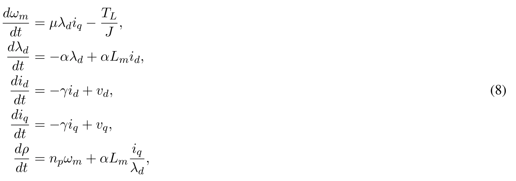
vdandvqare the new control inputs obtained by applying the next PI loops:

whereλdref,Trefandωrefare the references for rotor flux linkage,torque,and angular speed,respectively.Kd1,Kd2,Kq1,Kq2,Kτ1andKτ2are the positive constant gains.Temis the electromagnetic torque,defnied asTem=µJλdiq.
3 Mated system:robot manipulator and induction motor
Consider that thekth joint,k=1,2,···,n,of eachith robot manipulator,i=1,2,···,p,being directly driven by an IM.It is also assumed that the amplitude of the flux linkageλd,ikis regulated to the reference constant valueλdref,ikthrough the control loop Eq.(9);hence,the closed-loop system for each IM is reduced to

The closed-loop reduced model representing all thekinduction motors for theith robot manipulator is expressed as

The vector of the angular positionθi ∈Rnfrom all thekinduction motors for theith robot manipulator is defnied as

To mate the robot manipulator dynamics and induction motor dynamics,we consider the following assumptions.
▲Assumption 1.There exists a direct mechanical coupling between the rotor of the IM and the joint of the robot manipulator.This might reduce the periodical mechanical maintenance with respect to the PMBLDC motors;therefore,

▲Assumption 2.The synchronization control law causes the input torque or required torque for each joint of the robot manipulator,which is considered as the load torque applied to each induction motor;thus,

According to Assumption 2,it is possible to substitute Eq.(15) into Eq.(13);besides,Eq.(14) enables the state variables of the motor to equal those of the robot manipulator.
This gives

whereDi(qi)=Ji+Mi(qi).The mated system is called IM-Robot.
This model has the same properties as listed in Section 2,because(qi),remembering thatJiis a constant.
4 Synchronization control and velocity observer
4.1 Synchronization control in joint space
Synchronization errorssi,Rnare defnied as in [Rodriguez-Angeles and Nijmeijer(2004)]:

The reference signalsqriand,are established to consider the interactions between robots and ensure the synchronous behavior,as

whereqd(t)is the common desired trajectory that each IM-Robot will be forced to track;Kcp_i,j,Kcv_i,j,Kca_i,j ∈Rn×nare diagonal positive semi-defniite matrices,and,for simplicity,it is assumed that they satisfyKcp_i,j=Kcv_i,j=Kca_i,j=Ki,j.Thus,from Eq.(14)and Eq.(18),the reference signals for the mated IM-Robot system are obtained:

▲Assumption 3.The torque necessary to achieve synchronization for each jointτishall be the reference torqueTreffor the corresponding IM.This avoids the control loop PI Eq.(11)in the control scheme of the IM.
Taken from Torres et al.[Torres,Guerrero,Garcia et al.(2016)],the control law to achieve a master-slave synchronization of IM-Robot systems in the joint space is given by

whereKdiandKpiare positive-defniite gain matrices.
4.2 Synchronization control design in workspace
To attain synchronization of robot manipulators driven by IMs in the workspace,a controller design is given below,more details of which appear in Appendix A.
The position error in the workspaceei(t)∈Rmis defined as

The error dynamic equation is expressed as

whereαeihas been added and subtracted to facilitate the formulation of the control,In ∈Rn×nis the identity matrix,α ∈Rm×mdenotes a positive-definite gain matrix,andϑi(t)∈Rnis a signal constructed in accordance with the required control objective.
Based on the structure of Eq.(22),the filtered tracking errorri(,ei,)∈Rnis used to reduce the order of the error dynamic equation,which is defined as

Thus,the position error of the IM-Robot system in the workspace could be written usingri(t)∈Rnas

The dynamics of the filtered tracking error is obtained by applying the time derivative of Eq.(23):

Thus,the dynamic equation of the IM-Robot system in an open loop is written as

where the regression matrix/parameters vectorYiΦiis defined by

A candidate Lyapunov function is proposed to design the synchronization control in the workspace of IM-Robot systems:

The functionV(ri,ei) is positive-defniite for allri,eiandV(ri,ei) = 0 if and only ifri=0,ei=0.
The time derivative of the proposed Lyapunov functionV(ri,ei)is given by

By the skew-symmetric property of thematrix

is obtained.An equality is established to achieveV˙ (ri,ei)<0:

whereK ∈Rn×nis a constant positive-defniite gain matrix.
Thus,V˙ (ri,ei)is expressed as

In accordance with Behal et al.[Behal,Dixon,Dawson et al.(2009)],it is said the synchronization erroreiis global asymptotically stable.
A controller leading to master-slave synchronization of IM-Robot systems in the workspace is developed via Eq.(31)as

4.3 Joint variables estimator
Owing to the problems caused by the velocity measurements,an observer based on the model is used to estimateqiandq˙iin the slave IM-Robot systems.Then,the stability analysis is developed.For more details,see Appendix B.Thus,the proposed observer is

whereξ1andξ2are diagonal positive-defniite matrices.The position estimation errorRnand velocity estimation errorRnare given by

The estimation errors’dynamics is expressed as

The candidate Lyapunov function for the stability analysis is proposed as

where

P1andP2are diagonal positive-defniite matrices.The time derivative of the proposed Lyapunov function is given separately by

The closed-loop error dynamic equation of the IM-Robot system is expressed as

The Lyapunov function derivativemanifests an inequality given by

where

As of Eq.(42),the analysis is centered on the expression

as the cause of the non-negative defniition of the Lyapunov function derivative,thus obtaining a factorization with respect to:

This equation is≤0 if and only if

Therefore,the Lyapunov function derivative is rewritten as

Another condition for the negative defniition of the Lyapunov function derivative is for the positive-defniiteness of the matrix Δ to remain,which is ensured in accordance with Sylvesters criterion as

if and only if

where the sub-indexesmandMindicate the minimum and maximum matrix eigenvalues,respectively.
Definition 1.Lettingwi=and the matrix

the proposed Lyapunov function is rewritten as

In accordance with Khalil[Khalil(1996)],wi ≤κ⇒V(wi)≤α2(κ)=ε.This ensures that

Thus,wi ∈Ωεand the solutions areGUUB (globally uniformly ultimately bounded)by the bound

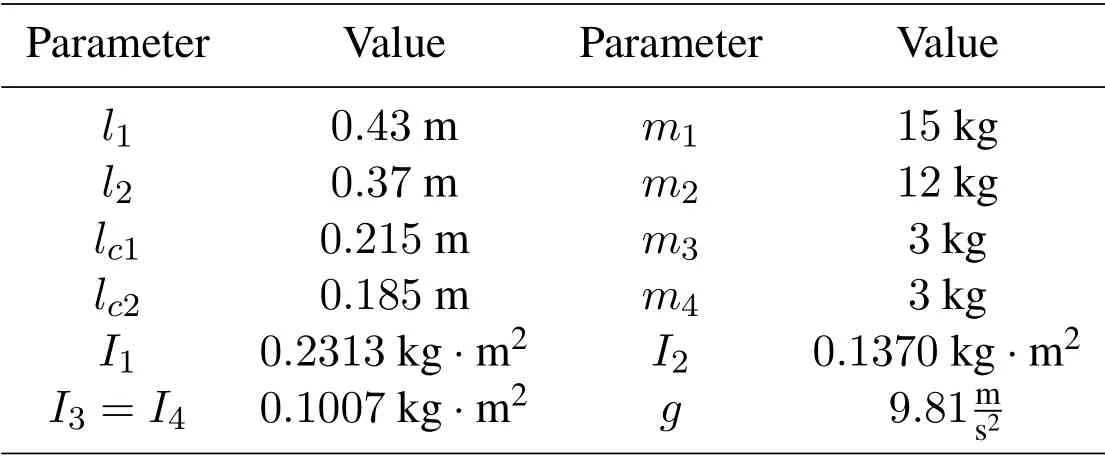
Table 1:SCARA robot manipulator parameters(BOSH○ RSR-8)
4.4 Synchronization control with velocity estimator
The synchronization control law of IM-Robot systems in the joint space with a velocity estimator of the slave IM-Robot is given by the expression

In contrast,the synchronization control law of IM-Robot systems in the workspace with a velocity estimator of the slave IM-Robot is expressed as

where

5 Simulation results
With the intention of proving the proposed synchronization approaches,robot manipulators of type SCARA withk= 4 joints driven by IMs were simulated in a scheme shown in Fig.(1) with one master IM-Robot system and three slave IM-Robot systems.The robot parameters are shown in Tab.1,taken from theBOSH○RSR-8datasheet.The parameters for each of the IMs appear in Tab.2.Simulations were carried out on theSimulink○Rplatform through the S-function level-2 with ode-45 solver,variable-step,and a simulation time of 10 s.The voltage sources can supply the required levels in the simulation settings.
5.1 IM-Robot synchronization in joint space
The desired trajectory in the joint space is described by the expression

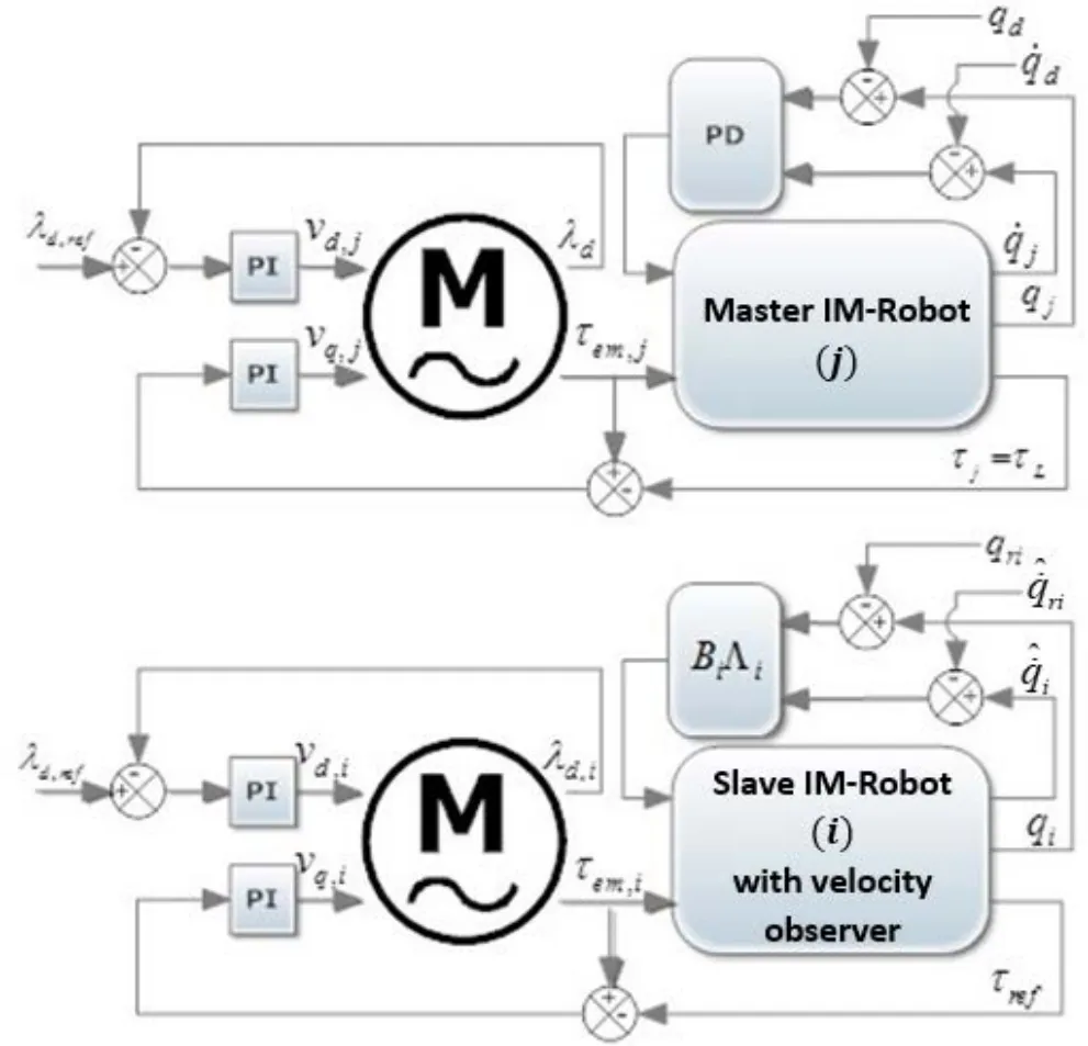
Figure 1:Simulation scheme for synchronization of IM-Robots
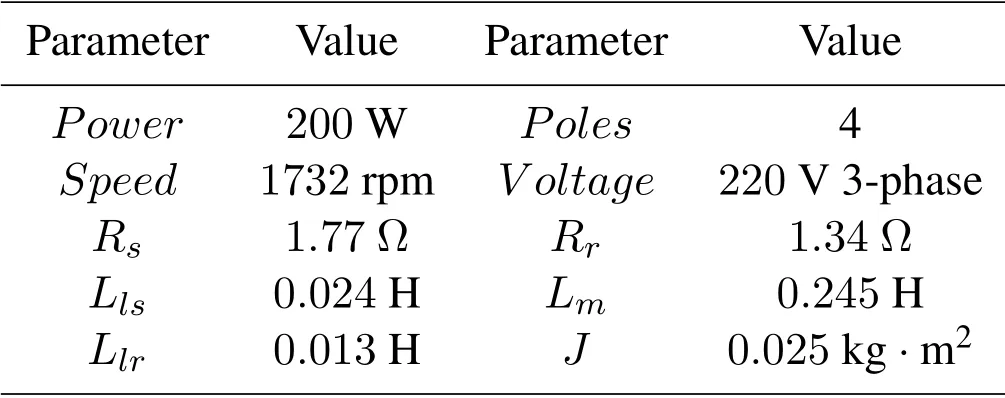
Table 2:IM Parameters
wheretfis the fnial time,set as 4 s.qdindenotes the initial desired position for each jointk=1,2,3,4.qdfis the fnial desired position.The values of these references are

The initial conditions for the joint position of the master IM-Robotjand the three slave IM-Robotsi=1,2,3 withk=1,2,3,4 joints are established as

The gain matrices for the synchronization controller in the joint space are set as

It should be noted that the process for gain tuning in relation to the proposed controller was guided based on our prior experience with these types of synchronization controllers,attending to the positive-defniite gain matrices.
The simulation results of the IM-Robot synchronization in the joint space for each slave IM-Robot are shown in Figs.2-4.A solid line denotes the master IM-Robot trajectory,and a dashed line the slave IM-Robot system.In Fig.5,all the trajectories are shown for each joint,including the desired trajectory.Synchronization errors and tracking error for each joint are displayed in Fig.6,whereζj,kis the tracking error of the master IM-Robot with respect to the desired trajectory.
Remark 1.In the joint space,all the trajectories of the slave IM-Robot systems synchronize with the trajectory of the master IM-Robot system for each joint after an initial transient of 1.5 s,depending on the initial conditions.Therefore,the synchronization errors and the tracking error converge to zero in the case in which the velocity measurement is estimated.
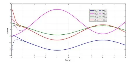
Figure 2:Synchronization in joint space of slave IM-Robot i1
5.2 IM-Robot synchronization in workspace
The desired trajectory in the workspace is described by

The initial position of the master IM-Robot end-effector is set as

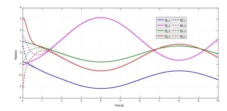
Figure 3:Synchronization in joint space of slave IM-Robot i2

Figure 4:Synchronization in joint space of slave IM-Robot i3
For each slave IM-Robot,i= 1,2,3,and the initial position for the end-effector is established as

The gain matrices used in the synchronization controller in the workspace are

The simulation results for IM-Robot synchronization in the workspace are presented as follows:In Fig.7,the synchronization is seen in thex-yplane;in Fig.8,it is seen in thex-zplane;fnially,the workspace synchronization errors on thexandyaxes are displayed in Fig.9.
Remark 2.In the workspace,every position and orientation of the slave IM-Robot endeffectors synchronize with the position and orientation of the master IM-Robot end-effector
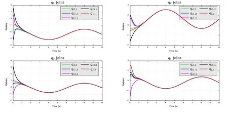
Figure 5:Syce of all IM-Robot slaves,each joint shown separately

Figure 6:Synchronization error and tracking error in joint space of all IM-Robot slaves,each joint shown separately
while tracking a common desired trajectory.Furthermore,the synchronization errors converge to zero without velocity measurements.
The gain matrices for the velocity observer in both the joint space and workspace are established as

Note that this choice of the gains satisfeis the conditions given in Eq.(47) for each slave IM-Robot system in the scheme.
The position estimation error is shown in Fig.10,and the velocity estimation position is presented in Fig.11.
Remark 3.It is clear that the estimation errors converge to zero in both the joint space and workspace.
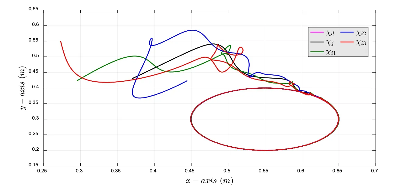
Fig ure 7:Synchronization in the workspace in the x-y plane
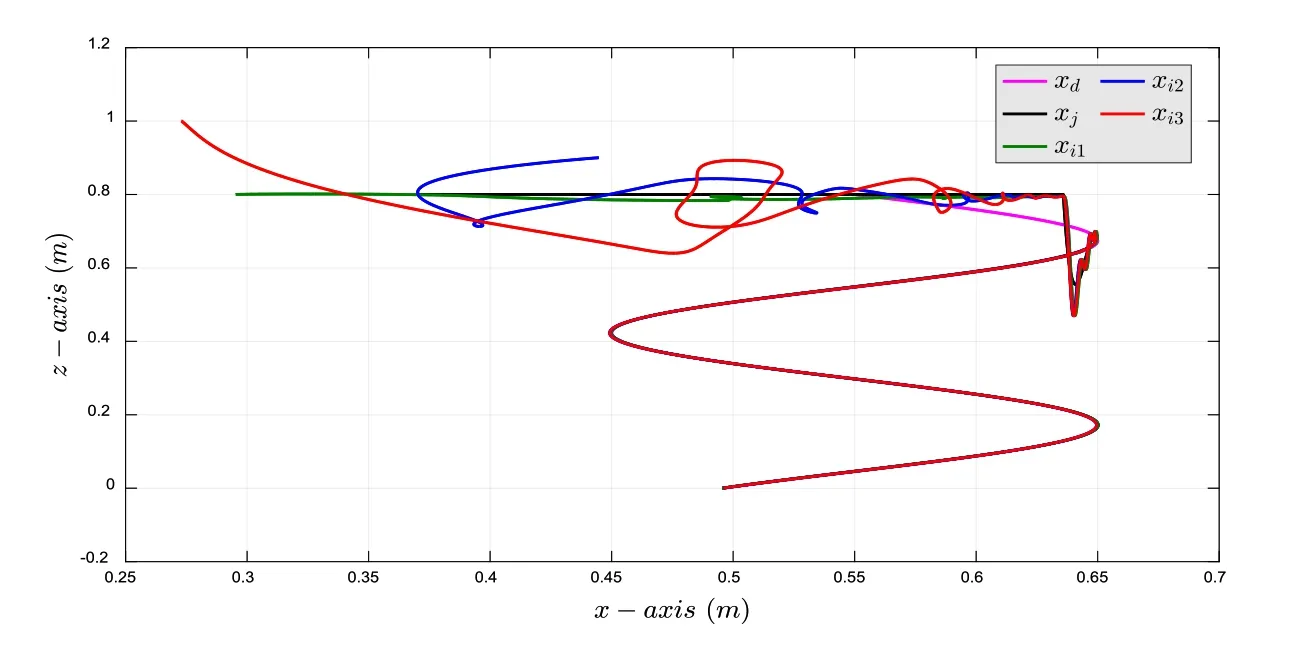
Figure 8:Synchronization in the workspace in the x-z plane
6 Conclusions
The dynamics of the robot manipulator and IM have been combined to obtain the entire dynamic model of the mated IM-Robot system.Thus,a novel synchronization scheme including the actuator dynamics within the synchronization control with a velocity observer based on the entire IM-Robot model has been satisfactorily achieved,in both the joint space and workspace.Considering a direct mechanical coupling between the rotor of the IM and the joint of the robot manipulator,the proposed approach realizes synchronization of both the IM and robot manipulator.
The IM-Robot systems synchronize before tracking the desired trajectory,which is similar to the case in prior works in the literature in which ideal actuators were considered,so the use of an actuator with high nonlinear dynamics,like the IM,might allow reliable performance while minimizing costs.
Based on the results of Lyapunov analysis,the proposed velocity observer exhibited GUUB estimation closed-loop errors.The simulation results,assuming knowledge of the parameters and availability of the partial state and ideal sources in the simulations,show the feasibility of the proposed synchronization approach.

Figure 9:Synchronization errors in the workspace on the x and y axes
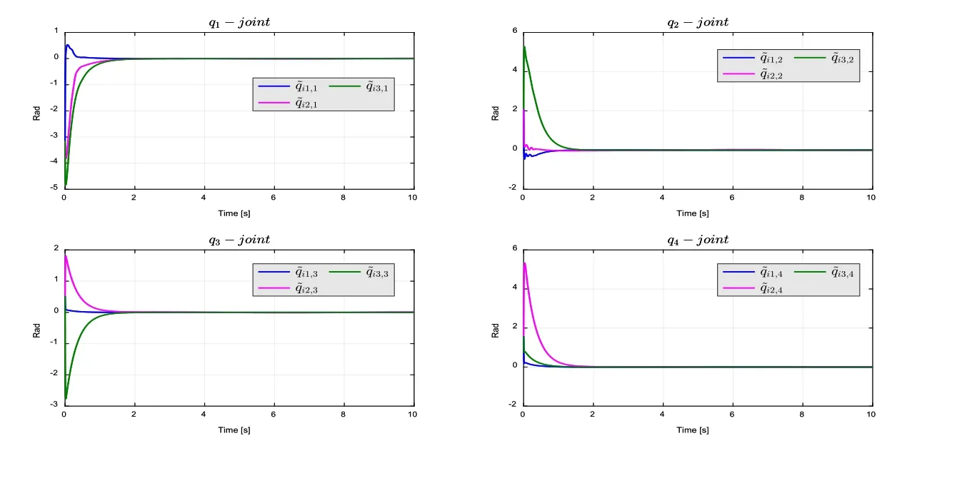
Figure 10:Position estimation err or for the synchronization in joint space

Figure 11:Velocity estimation error for the synchronization in the workspace
Future works will be directed at obtaining experimental results to compare the effects of chattering caused by the noise in the velocity measurements against the performance of the proposed observer.Moreover,future approaches will be undertaken that include time delays and parametric uncertainties.
Acknowledgement:This research was supported by University of Guanajuato-PFCE2019.We would also like to express our gratitude to the Department of Mechanical Engineering for supporting the academic resources needed for this work.
Appendix A.
In this appendix,the design of the synchronization controller in the workspace is presented in detail as follows.From the Eq.(25),it is multiplied by the inertia matrixDi(qi) of the matched IM-Robot system,then substitution of the IM-Robot dynamics results in the expression:

To reconstruct the structure of Eq.(23),is added and subtracted to Eq.(63),which gives

Substitution of Eq.(26)into Eq.(29)results as

Appendix B.
This appendix shows details of the stability analysis of the proposed observer given in Eq.(34).
Substitution of Eq.(41) into Eq.(39) results as

Substitution of Eq.(36)into Eq.(40)gives

Therefore,

Considering a matrix representation,

 Computer Modeling In Engineering&Sciences2019年11期
- Computer Modeling In Engineering&Sciences的其它文章
- IDSH:An Improved Deep Su pervised Hashing Method for Image Retrieval
- Numerical Simulations of the Ice Load of a Ship Navigating in Level Ice Using Peridynamics
- Research on Nonlinear Frequency Compression Method of Hearing Aid with Adaptive Compression Ratio
- Feature Selection with a Local Search Strategy Based on theForest Optimization Algorithm
- Some Remarks on the Method of Fundamental Solutions for Two-Dimensional Elasticity
- A Parametric Study of Mesh Free Interpolation Based Recovery Techniques in Finite Element Elastic Analysis
