Numerical Simulation of Dynamic Interaction Between Ice and Wide Vertical Structure Based on Peridynamics
Bin Jia,Lei Ju, and Qing Wang
1College of Shipbuilding Engineering,Harbin Engineering University,Harbin,150001,China.
Abstract:In the ice-covered oceanic region,the collision between sea ice and offshore structures will occur,causing the crushing failure of ice and the vibration of structures.The vibration can result in fatigue damage of structure and even endanger the crews’ health.It is no doubt that this ice-structure interaction has been noted with great interest by the academic community for a long time and numerous studies have been done through theoretical analysis,experimental statistics and numerical simulation.In this paper,the bond-based Peridynamics method is applied to simulate the interaction between sea ice and wide vertical structures,where sea ice is modeled as elastic-plastic material,with a certain yield condition and failure criterion.Oscillation equation of single-degree-of-freedom is considered to investigate the vibration features of the structure during the interaction process.The damage of ice,ice forces and vibration responses of structure in the duration are obtained through numerical simulation.A parametric investigation is undertaken to identify the key parameters,such as ice thickness,the diameter of structure and relative velocity that trigger the ice crushing,ice forces and vibration responses of the structure.Results indicate that all three parameters have a positive correlation with the overall level of ice force and vibration displacement.Besides,a velocity coefficient is proposed to predict the vibration displacement based on its relation with ice speed.
Keywords:Ice,Peridynamics,vertical structure,interaction.
1 Introduction
With increasing attention attracted by the polar area,ice-related issues have been deeply studied by researchers around the world.For various types of marine structures,they could inevitably contact with ice floating on the water during their operation.However,the complex characteristics of sea ice make this ice-structure interaction problem even harder to solve.Marine platforms in the ice-covered area are mainly in the form of cone,slope,and cylinder.As a widely-used structural type,vertical cylindrical structures would cause the crushing failure of sea ice.In return,the interaction creates structural vibration,which induces the risk of fatigue damage to the structure.
There have been several research achievements about the interaction between the sea ice and vertical structure.Research focuses mainly on theoretical analysis [Matlock,Dawkins and Panak (1969);Eranti (1991);Withalm and Hoffmann (2010);Ji and Oterkus (2016);Hendrikse (2017) and etc.] and experimental studies [Sodhi and Morris (1984);Sinding-Larsen (2014);Huang,Shi and Song (2007) and etc.].Meanwhile,numerical simulation is becoming a promising method to investigate relevant problems,owing to its remarkable operation convenience,high computational efficiency and relatively low cost.Feng et al.[Feng,Pang and Zhang (2016)] used cohesive element method,which is integrated in LSDYNA,to simulate the failure of ice and output ice forces generated during the process;Di [Di (2015)] carried out discrete element simulation of ice action on vertical structure based on GPU parallel algorithm,which revealed the non-simultaneous failure features of sea ice.Considering ice as visco-elastic-plastic material,Wang et al.[Wang,Yang,Zhang et al.(2017)] applied Material Point Method to predict the ice load and discuss the influence of parameters like temperatures and velocities.
The most significant phenomenon in ice-structure interaction is the crack failure of ice.There are several particle methods that can describe fracture features of material.Rabczuk et al.[Rabczuk and Belytschko (2004)] presented cracking-particle method (CPM),a simplified meshfree method for arbitrary evolving cracks where the crack growth is represented by activation of crack surfaces at each particle.Therefore,CPM could be used for simulating large deformations and arbitrary nonlinear and rate-dependent materials [Rabczuk and Belytschko (2007)].Based on that,Rabczuk et al.[Rabczuk,Zi,Bordas et al.(2010)] modeled the crack by splitting particles located on opposite sides of the associated crack segments as a modification.In addition,Areias et al.[Areias,Msekh and Rabczuk (2016);Areias,Reinoso,Camanho et al.(2018)] proposed a crack propagation algorithm,which is composed of a localization limiter in the form of the screened Poisson equation with local mesh refinement,where the crack growth has been proven to be able to emerge naturally.
Peridynamics (PD) is a meshfree numerical method,whose fundamental theory was proposed by Professor Silling in 2000 [Silling (2000)].Based on non-local interaction ideology,Peridynamics works by solving governing equations in integral form,which naturally avoids continuity hypothesis and the problems of solving partial differential equations [Silling and Askari (2005)].In this way,Peridynamics shows a clear advantage on discontinuous problems like fracture,making it feasible to simulate the rupture characteristics of sea ice when interacting with marine structures.Liu et al.[Liu,Xue,Lu et al.(2018)] and Liu et al.[Liu,Wang and Lu (2017)] simulated the ship navigation in ice rubbles and interaction between ice and vertical structure using peridynamics successfully.With an uncomplicated principle,bond-based peridynamics is rather easy to realize.It can describe the characteristic of certain material models including prototype micro-elastic brittle (PMB) model and micro-plastic (MP) model,which could be expressed by some plain types of force density function.To a certain extent,bond-based peridynamics avoids some complex handlings like modification of zero-energy mode,making it own higher application flexibility in certain cases.Bond-based peridynamics has been proven effective in various problems,such as quasi-static deformation and dynamic damage.Gu et al.[Gu,Zhang,Huang et al.(2016)] even applied modified bond-based peridynamics to research the elastic wave dispersion and propagation.Based on bond-based peridynamics,Ren et al.[Ren,Zhuang,Cai et al.(2016)] proposed dual-horizon peridynamics that could solve unbalanced interactions between the particles with different horizon sizes,which possesses clear superiority in capturing complex fracture and owns higher computational efficiency with adaptive refinement.It can completely realize the removal the ghost force and is suitable for nonuniform discretization [Gu,Zhang and Xia (2016)].However,it should be noted that bond-based peridynamics does have some drawbacks.For instance,only the isotropic material with Poisson's ratio of 1/3 in 2D or 1/4 in 3D can be modeled.And it can’t be simply applied when constitutive relation of material is complicated.Meanwhile,the quantities that matter in mechanics (like stress,strain etc.) could not be obtained directly through this method,which weakens the relation with traditional continuum mechanics.In addition,it does not distinguish the dilatational and distortional parts of the deformation [Gu,Madenci and Zhang (2018)].
Sea ice is a type of extremely complicated material,whose physical and mechanical properties could be easily affected by temperature,sanity,brine volume and etc.In this way,there emerged various kinds of constitutive models to depict the characteristics of sea ice when it moves against certain structure.Among them,the most widely accepted constitutive model is the visco-plastic model firstly presented by Hibler,which has always been a basic for following academic extension [Hibler (1979)].And simple elastic-brittle constitutive model has also applicable for some high-strain-rate scenarios [Liu,Wang and Lu (2017);Wang,Wang,Zan et al.(2017)].Different from above,Ralston investigated the yield conditions and plastic deformation before its failure,providing feasibilities to apply knowledge incorporated with elastic-plastic theory to study on failure of ice [Ralston (1977)].As a matter of fact,Coon et al.[Coon,Maykut and Pritchard (1974);Pritchard (1975);Coon,Knoke,Echert et al.(1998)] had proposed isotropic and anisotropic elastic-plastic laws for the use of numerical dynamic simulations of sea ice at relatively large scale.In 2015,Gao et al.[Gao,Hu,Ringsberg et al.(2015)] presented an ideal elasto-plastic model,which has been validated to be efficient to predict the collision between ice and ship.
In this paper,a bond-based Peridynamics method is used to simulate the interaction between sea ice and a wide vertical structure.Sea ice is modeled as ideal elastic-plastic material,which is realized by micro-plastic (MP) model in Peridynamics.To provide more practical data,a single-degree-of-freedom vibration equation is considered to well explain the ice-structure coupling effect.Numerical results including ice force and vibration displacement are compared with numerical data from DEM simulation carried out by Ji et al.[Ji,Di,Li et al.(2013)].It shows that two sets of data hold favorable consistency,verifying the effectiveness and practicability of Peridynamic algorithm in ice-related scenarios.Based on that,parameter sensitivity analysis is undertaken to conclude the influence of parameters like the diameter of structure,ice thickness and ice speed,which is appropriate for revealing the mechanism of ice-structure interaction.
2 Peridynamic theory
In Peridynamic theory,the material points in an object could only interact with points around them within a certain scope,as shown in Fig.1.
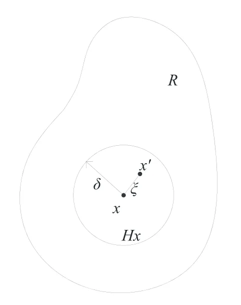
Figure 1:Interaction between material points in Peridynamic frame
These interactions between material points would appear as non-local forces.For an objectRoccupying a particular space region at timet,the governing equation of a single material point inside could be written as [Silling (2013)]

whereρis material density,uis the displacement vector of material pointxat timetandbis the body force acting on the material point.Hxis a horizon centered with the materialpointx,which is defined by a zone radiusδ.Andx’is a material point located in thehorizon of material pointxso that an imaginary “bond” could be created connectingxandx’.fis the force density function representing the interaction state betweenxandx’.
In Peridynamic framework,MP model could be used to describe ideal elastic-plastic features of the material.The force density functionftakes the form [Parks,Seleson,Plimpton et al.(2011)]

whereξandηdenote initial relative position vectorξ = x-x' and relative displacement vector after deformationη=u(x',t) -u(x,t)respectively;The material parametercis referred as the bond-constant.For general three-dimensional structures,cis expressed as [Silling and Askari (2005)]

whereKis bulk modulus of material;However,the formula above considers that material points within horizon act on the centered material point to the same extent no matter where they locate at.It’s reasonable to recognize that those closer material points should interact more intensively with the centered one.In this way,researchers have derived a function to express this thought,which could be written as follows [Wang,Wang,Zan et al.(2017)]:

sdenotes the stretch of the bond,which is defined as follows [Silling and Askari (2005)]

s p(t) is the plastic stretch history which follows

wheresYis the yielding stretch.
It should be emphasized that if the material is isotropic,sshould be positive when the bond is in stretching status and negative when bond is under compressive condition respectively;µ(t,ξ) is a scalar quantity that represents the damage state of “bond”,which is written as wheres0is critical stretch,a quantity that determine whether bond has been broken.Whensexceedss0,the bond could be regarded as damaged.Theoretically,critical stretch could be derived from energy release rate of the fracture section.

Furthermore,another coefficientϕ(x,t),was proposed by Silling to describe the local damage of material point [Silling and Askari (2005)].

The coefficientϕranges from 0 to 1.ϕ=0 means that bonds connected to material pointxare all intact.Andϕ=1 indicates that there is no more interaction betweenxand other material points within its horizon.
3 Numerical implementation
3.1 Constitutive model of sea ice
A complex feature of sea ice lies in its strength difference in tension and in compression.As a rule,the compressive strength is 2~4 times larger than its tensile strength [Karr and Das (1983)].In this way,a relation ofsc=-4·s0is chosen to reflect its strength-difference effect.To simplify the problem,it assumes that ice only yields under compression.From the above,the constitutive relation of ice is shown in Fig.2.
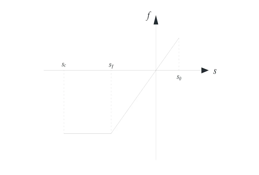
Figure 2:Constitutive relation of sea ice
Besides the method mentioned above,inspired by Huang et al.’s work,critical stretch can be approximated as [Huang,Lu and Qiao (2015)]

whereσtis the tensile strength of the material.In this paper,the critical compressive stretch is calculated by the equation above with slight change from tensile strength to compressive strength.Then the critical tensile stretch is evaluated from the 4-time multiple relationships between two kinds of strengths mentioned above.
In addition,the bond yield stretch should be related to the conventional continuum mechanics properties,i.e.,engineering ultimate strengthσs,by noting that all bonds have yielded when the material reaches its ultimate strength.The relation between the two could be expressed as [Macek and Silling (2007)]

whereσsis also referred to yield strength (MPa).
3.2 Contact model
Since the vertical structure,i.e.,impactor,is assumed to rigid,only the target material would be deformable and those material points within are governed by the Peridynamic equation of motion.It assumes that the impactor moves towards the material point with its constant velocityv0at the beginning,as illustrated in Fig.3(a).At timet+Δt,a contact takes place between the material point and the impactor,inducing an interpenetration of material points (see Fig.3(b)).From the perspective of reflecting the physical reality,the material points are relocated to their new positions outside the impactor.Their new locations are assigned to achieve the closest distance to the surface of the impactor,as shown in Fig.3(c).
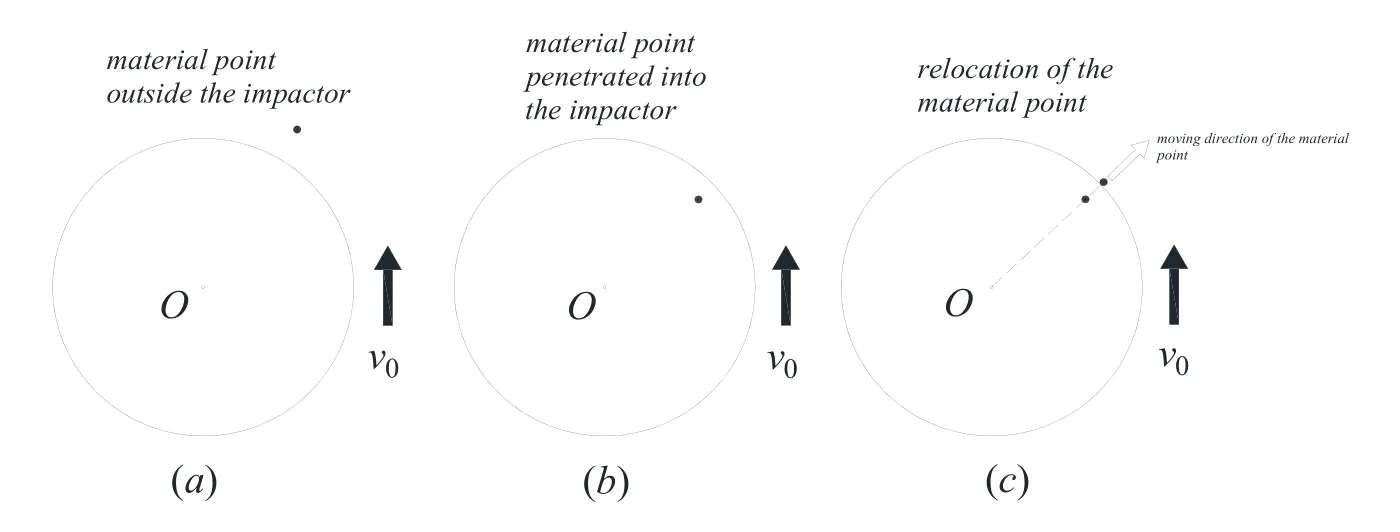
Figure 3:Relocation of a material point inside the target material to reflect the contact phenomenon.(a) Time,t.(b) Time,t +Δt .(c) Time,t +Δt (relocation)
According to the cases in this paper,the distancedshould be calculated as

whereRis the radius of the structure,d0is the distance between penetrated material point and the center of the structure.So that the new location could be written as

The velocity of the material pointx(k),in its new location at timet+Δt,can be expressed as [Ye,Wang,Chang et al.(2017)]

whereis the modified displacement vector at timet+Δt,is the displacement vector at timet,andis referred as time increment.In this way,the contribution to the contact force from this certain material point to the impactor could be computed from

whereis the velocity vector at time before relocating the material pointx(k),withρ(k)andV(k)representing its density and volume,respectively.The total contact force on the impactor can then be obtained by adding up the contributions of all material points inside the impactor.

wherendenotes the amount of material points penetrated in the impactor.
3.3 Dynamical model of the structure
Compared to inclined or conic structures,vertical structures would vibrate more violently while interacting with sea ice.The phenomenon of ice-induced vibration could be considered as an ice-structure coupling problem.In this paper,this vibration-related mutual effect is simplified as a single-degree-of-freedom system,where the vertical structure is regarded as an oscillating body with certain massM,structural stiffnessKand damping factorCand its motion are limited in horizontal direction.The vibration model is shown in Fig.4.
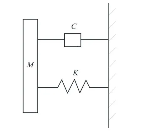
Figure 4:Single-degree-of-freedom vibration model of the vertical structure
The vibration equation of a single-degree-of-freedom should be written as

and the central difference method is used to solve the physical quantities in it.
3.4 Numerical computational algorithm
When it comes to numerical calculation,the continuum should be divided into a series of closely linked material points in the cartesian coordinate system.Meanwhile,the integral part of the governing equation could be transformed into a limited sum form so that the numerical governing equation should be expressed as

wherexjrepresents those material points within the horizon of centered material pointxi.mis the quantity ofxj.uiandujare the displacements of material pointxiandxjrespectively.is the acceleration ofxi,biis the body force acting onxiandVjis the volume ofxi.
In order to capture the motion of material points involved,the explicit central difference formula is introduced to calculate the acceleration of the material points

And for the purpose of ensuring the stability of the numerical method,the time increment should satisfy the limitation that [Madenci and Oterkus (2014)]

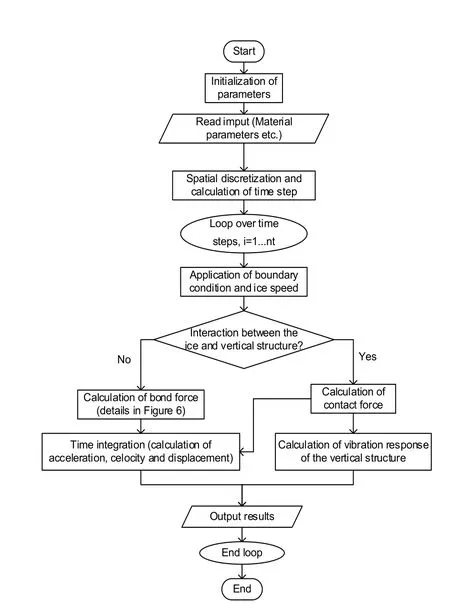
Figure 5:Flow chart of numerical calculation
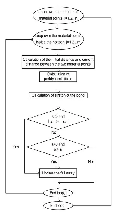
Figure 6:Calculation flow chart of the bond force
4 Model validation based on three-point bending test
Peridynamic model in this paper is verified through three-point bending test.Schematic diagram is shown in Fig.7.The ice sample for experiment is taken from a lake in Heilongjiang Province of China.The dimension of ice beam is 0.65 m×0.07 m×0.07 m,while the distance between the bearing points is 0.6 m [Lu (2017)].Based on experimental data,the densityρis 896.977 kg/m3,elastic modulusEis 6.81 GPa,and the flexural strengthσfis 2.5 MPa.
Based on the experiment,numerical model is built with a grid layout of 93×10×10.Horizon radius is set to be 3 times the material point size.In general numerical simulation of sea ice,its yield strengthσyis usually chosen as 2.12 MPa [Zhu,Qiu,Chen et al.(2016)],which is of use in the speculation of tensile strengthσtof it together with the flexural strengthσf.According to Jin et al.’s mean strength criterion,the relationship among the quantities above can be expressed as [Jin,Yue,Bao et al.(1997)]

Figure 7:Schematic diagram of three-point bending test

wherehrepresents the height of beam sample.Based on the relation above,the tensile strength can be obtained as 2.31 MPa.Therefore,the critical stretch could be derived from Eq.(10).In addition,a constant velocity load of 0.763 mm/s is applied on the center of the ice beam.Time step size is 2.5×10⁻⁶s.The simulated results show the process of crack initiation,crack growth until the failure of ice beam occurs (as shown in Fig.8).
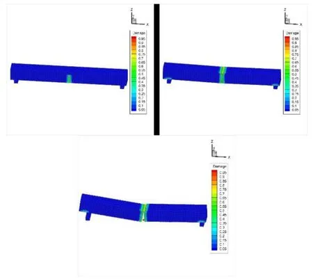
Figure 8:Simulated fracture process of ice beam in the three-point bending test
Besides,deflections of middle point calculated based on proposed numerical model and that recorded during experimental process are compared and show good agreement (as shown in Fig.9).It is noted that the calculated moment when ice beam breaks seems to be a little later than that in the experiment,which can be explained by the fact that the ice in numerical simulation is more close to ideal state while that in the experiment is formed with defects and impurities in a natural setting and weakens its strength.Comparative analysis shows the potential of numerical model to describe characteristic of ice and validates the method used to determine the critical stretch effectively.
5 Interaction between sea ice and vertical structure
Considering that the accuracy of the numerical results calculated in this paper would be validated by comparing with the data computed by DEM method,the parameters including density and ice thickness used in this numerical example are chosen according to Ji et al.’s DEM simulation settings [Ji,Di,Li et al.(2013)].Since the sea ice involved in the DEM simulation is assumed to be taken from the Bohai sea,material parameters including elastic modulus,compressive strength and yield strength are referred to experimental data and conclusion,and other settings of numerical simulation [Bai,Liu,Li et al.(1999);Meng (1993);Zhu,Qiu,Chen et al.(2016)],which are listed in Tab.1 below.
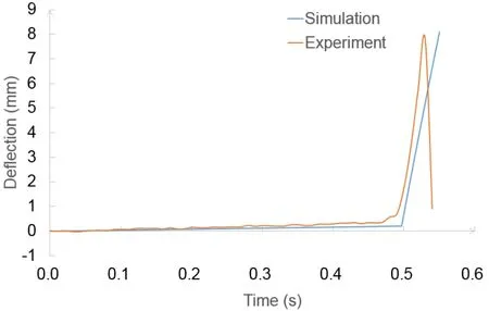
Figure 9:Deflections of middle point of ice sample in simulation and experiment
In order to manifest its semi-infinite characteristic in width and ignore the boundary effect,ice model is fixed at circumference except for the face that contact takes place.The schematic diagram of the calculation model and the corresponding coordinate system with it is shown in Fig.10.Among those parameters related to Peridynamic calculation,the ice model is divided into 3 layers in the direction of thickness,with the material point size approximately equaling 0.087 meters;90 material points are assigned in length and width direction;to achieve relatively higher computational accuracy,horizon radius is set to be 3 times the material point size as well;and time step size is chosen as 1.0×10⁻⁴s.
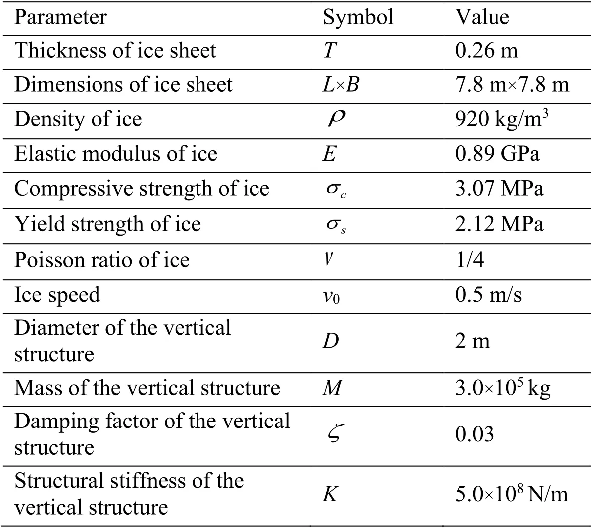
Table 1:Computation parameters
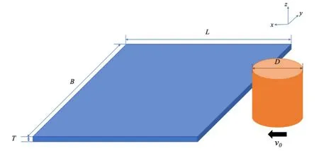
Figure 10:Schematic diagram of the interaction between ice and vertical structure
Typically in a situation like this ice-structure interaction,ice sheet often constantly breaks into pieces with the structure’s moving.As for qualitative results,Fig.11 presents the crushing failure of sea ice during the interaction process.It proves that the numerical method based on Peridynamics can simulate the ice-structure interaction reasonably,reflecting the physical reality.And as depicted in Fig.12 (fully damaged material points have been erased),the middle material point in its thickness direction is damaged more severely than its top one and the bottom one.Though stress states of material points cannot be obtained directly in the bond-based Peridynamic framework,to a certain extent,the damage of material does prove the intensity of the ice-structure interaction.The highlydamaged material point is more like the hot point in the “high-pressure zone” theory,which confirms the non-simultaneous failure pattern of sea ice when interacting with a relatively wide marine structure from another perspective [Liu,Wang and Lu (2017)].
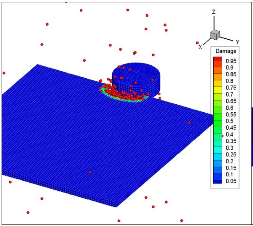
Figure 11:The global damage of simulation of ice-structure interaction (time step=5440)
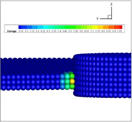
Figure 12:The local damage of simulation of ice-structure interaction (time step=28160)
Fig.13 describes the computed horizontal ice loads applied to the vertical structure during the interaction process when ice speed is 0.5 m/s.According to the figure,the plot of ice loads exhibits irregular fluctuation,which reflects its high degree of randomness.In addition,the vertical structure’s vibration displacement and acceleration during the simulation are shown in Figs.14 and 15,whose trends are generally consistent with those corresponding ones in DEM simulation by Ji et al.[Ji,Di,Li et al.(2013)].
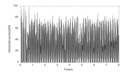
Figure 13:Dynamic ice force on vertical offshore structures during the simulation
Besides,Tab.2 lists the analysis results of horizontal ice loads,vibration displacement and vibration acceleration of vertical structure for comparison with data calculated by DEM simulation in Ji et al.’s work [Ji,Di,Li et al.(2013)].It turns out the numerical results agree quite well to each other,which further proves the validity of the numerical model in this paper.
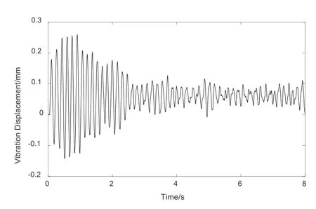
Figure 14:Vibration displacement of the vertical offshore structure during the simulation
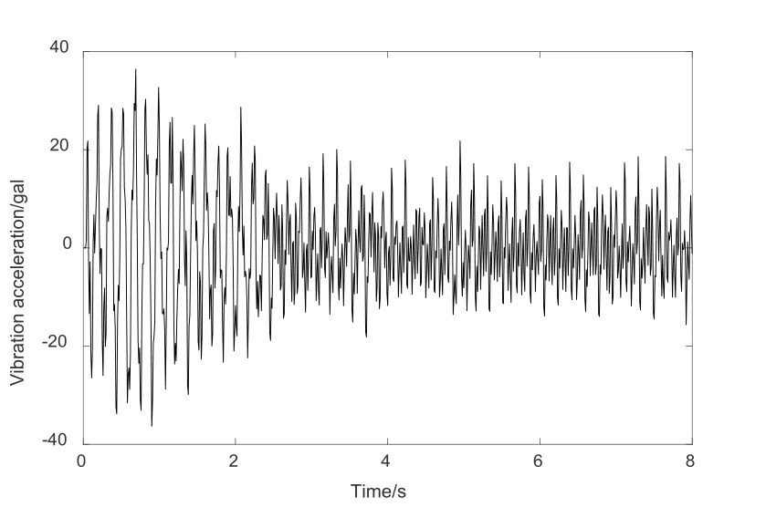
Figure 15:Vibration acceleration of vertical structure during the simulation
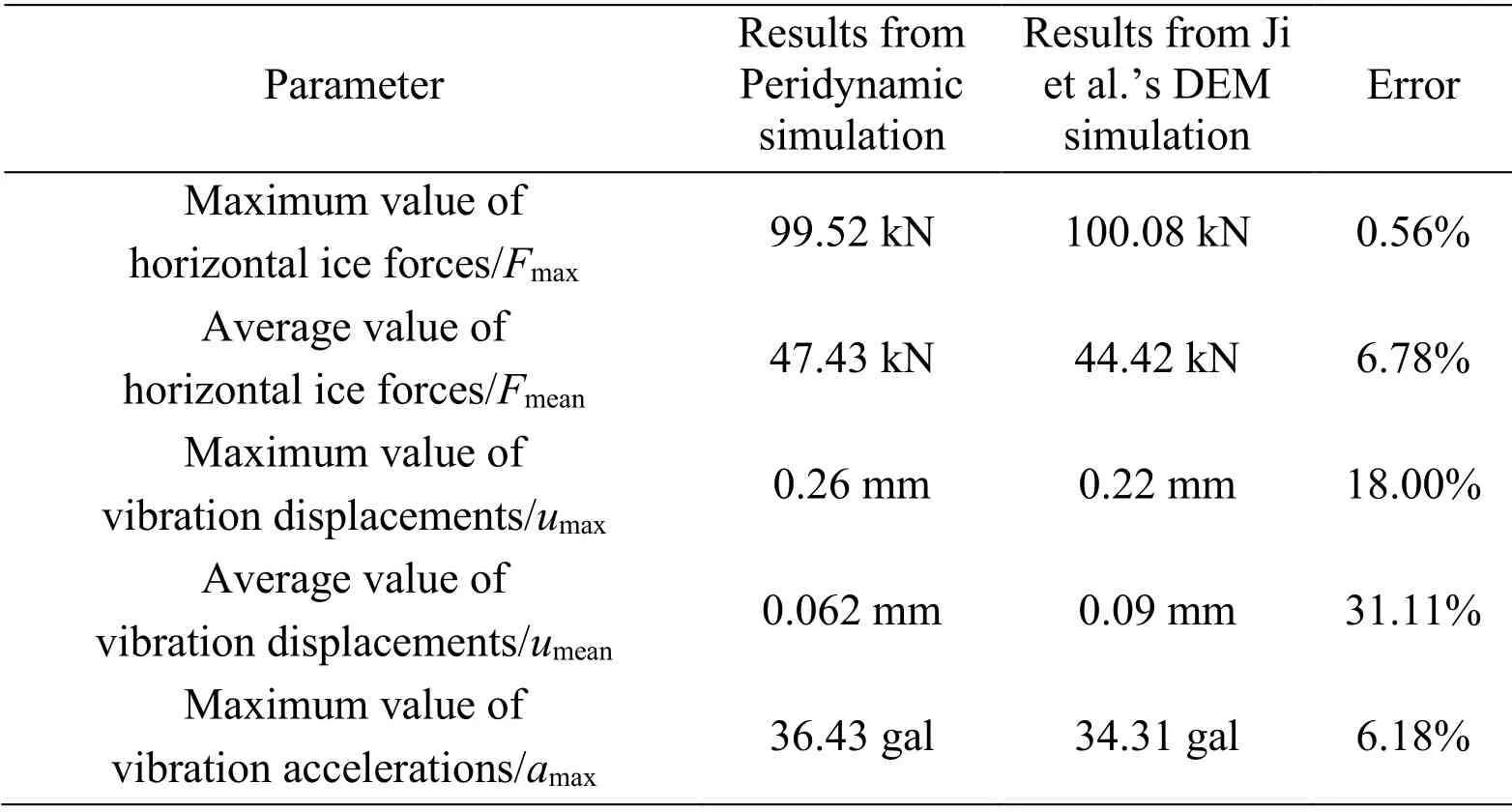
Table 2:Results calculated by Peridynamics and in Ji et al.’s DEM simulation
6 Sensitivity analysis
6.1 Diameter of structure and ice thickness
Both the diameter of structure and ice thickness contribute to the contact area,which directly reflects the degree of interaction between the two.Besides,the quotient of these two parameters determines the stress condition of sea ice,affecting the failure of it.Therefore,the effects of the diameter of structure and ice thickness are discussed in detail.Firstly,based on numerical model mentioned,different diameters of vertical structure,including 1.2 m,1.6 m,and 2.4 m,are chosen to investigate how it affects the horizontal ice force and vibration displacement during the interaction process.In these cases,ice speed is still taken as 0.5 m/s and other parameters remain unchanged.
Tab.3 presents the result of horizontal ice force.
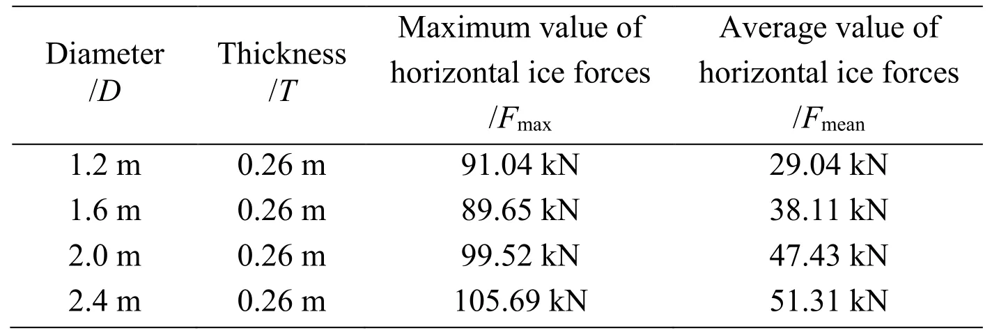
Table 3:Horizontal ice forces with various diameters of structure
It is noted that the peak value in the first case (D=1.2 m) is slightly higher than the peak value when theDis set as 1.6 m,which might be concerned with the simultaneous failure of ice with a relatively small diameter at a certain instant.Fig.16 shows the relation between the diameters of structure and horizontal ice forces in chart form.As it is shown,horizontal ice forces monotonically increase with the increase of diameter in general.It can be explained by the larger contact area and sufficient contact under the circumstance of larger diameters,which consequently causes an increase of the overall level of the random ice forces.
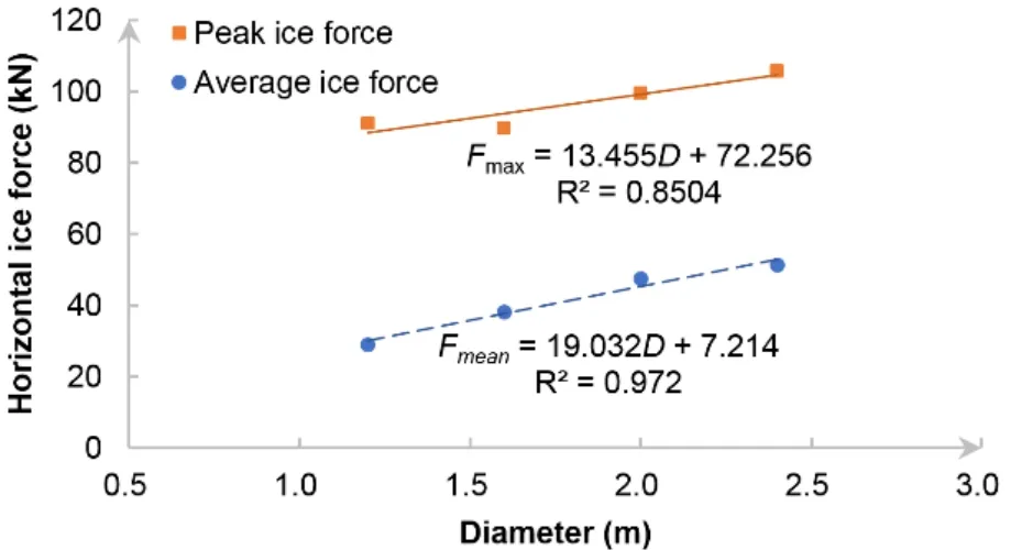
Figure 16:Horizontal ice loads under various diameters of the vertical structure
As well,structural vibration displacements with various diameters of the vertical structure are given in Tab.4.

Table 4:Vibration displacements with various diameters of structure
And as the graph below illustrates,both the peak value and average value of vibration displacements increase with the diameter.The reason for these may be that the larger diameters lead to a relatively higher-level horizontal ice force,which elevates the external excitation imported in the vibration system and induces more violent vibration responses.
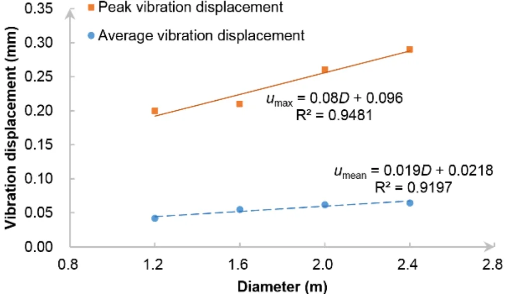
Figure 17:Vibration displacements under various diameters of the vertical structure
Likewise,a series of ice thickness values are imported to the program to study its influence on the interaction.The results of horizontal ice forces and structural vibration displacements are given in Tab.5.Fig.18 describes the relation between ice thickness and ice forces.And Fig.19 demonstrates the characteristics of vibration displacements with a changing thickness.
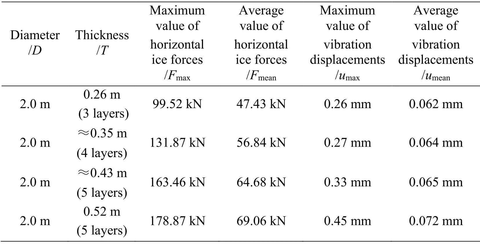
Table 5:Numerical results with various ice thickness (v0 =0.5 m/s)
It can be concluded by a comparative study that ice thickness plays a similar role as the diameter of structure in the analysis of ice-structure interaction,where they both contribute to the contact area directly.
The relation between the effective pressure and the effective contact area are studied in this section.Based on data from the numerical cases above with varied ice thickness and diameter,the area-pressure curve is plotted,as shown in Fig.20.The effective contact area is taken as the product of ice thickness and diameter of the vertical structure,then the effective pressure is the quotient of mean ice forces and the contact area.It is clear that the effective pressure does reduce with the increase of contact area,whose trend agrees well with former research achievements [Sanderson (1988);Masterson,Frederking,Wright et al.(2007)].In addition,it is found that the quotient ofFmaxandFmeandecreases with the diameter-thickness ratio,which is consistent with Sodhi and Morris’s experimental results and Kry’s proposition related to this quotient value and the width of structure [Sodhi and Morris (1984);Kry (1978,1979,1981)].
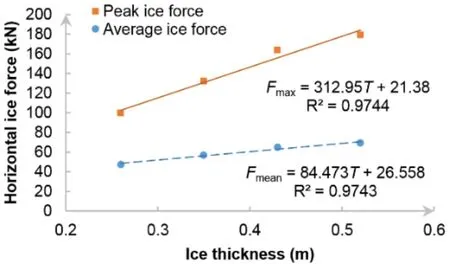
Figure 18:Horizontal ice loads under various ice thickness
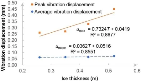
Figure 19:Vibration displacements under various ice thickness
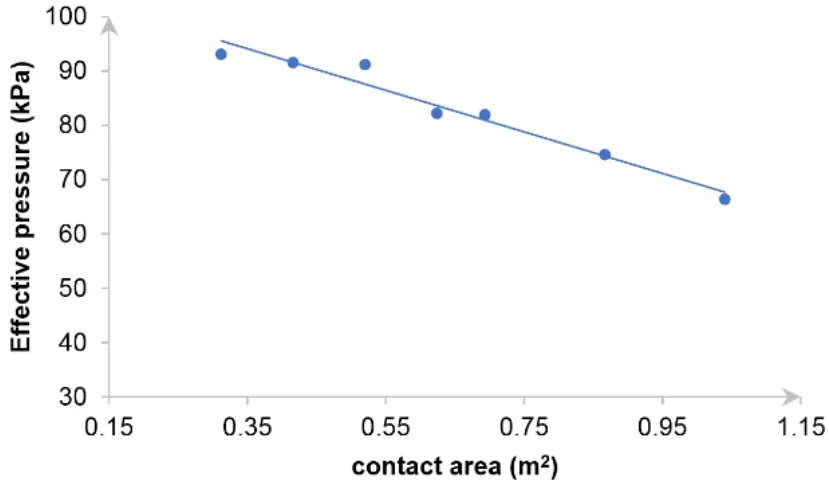
Figure 20:Effective pressure vs.contact area
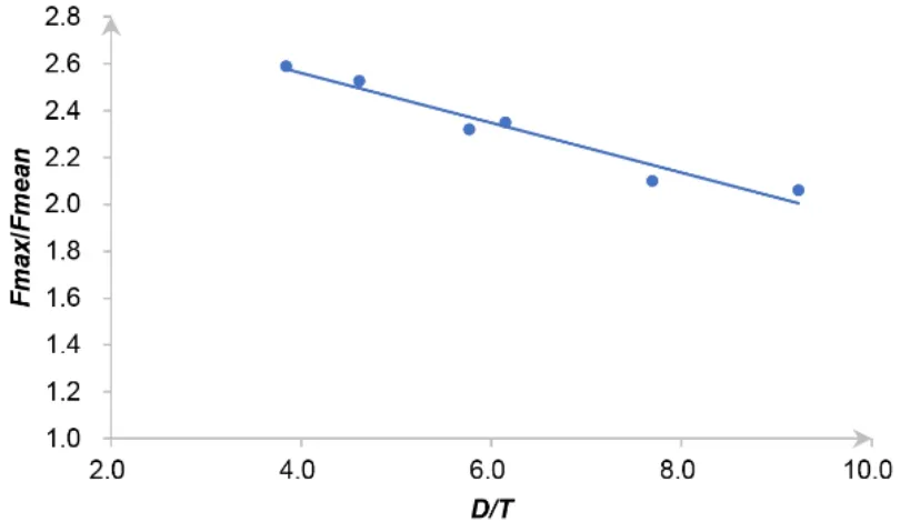
Figure 21:The ratio of maximum force to mean force Fmax/Fmean versus the diameter-thickness ratio D/T
6.2 Ice speed
Ice speed is directly related to the strain rate of sea ice in this scenario.Considering that sea ice is a type of material whose failure is sensitive to strain rate,ice speed is also taken as a significant influence factor in these interactions.
Ice speed value involved in this section are chosen as 0.3 m/s,0.5 m/s,0.7 m/s and 0.9 m/s,other parameters are same as those set in the initial case.The results calculated in this part are shown in Tab.6,Fig.22 and Fig.23 below.
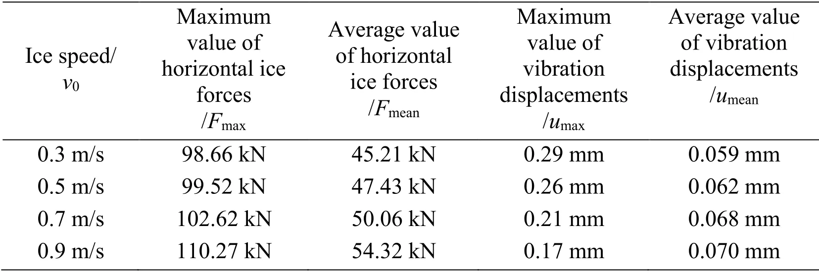
Table 6:Numerical results with various ice speed (D=2.0 m,T=0.26 m)
According to the numerical results,though the average value of ice force in these 4 cases is similar,it is found that ice load has a positive correlation with ice speed.But interestingly,with the ice speed increases,the maximal vibration displacement is in decline and the average value of vibration displacement rises gradually.It can be understood that the higher ice speed leads to a higher vibrational frequency,which lowers the vibration amplitude and lifts up the overall level of the vibration at the same time.
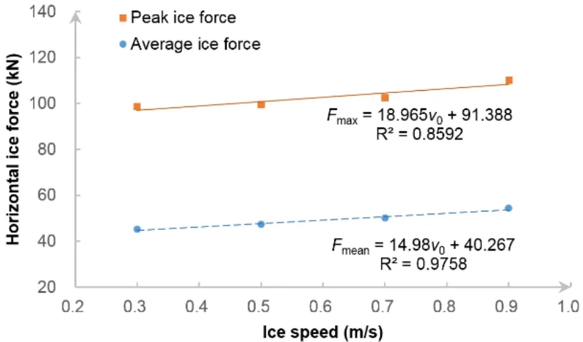
Figure 22:Horizontal ice loads under various ice speed
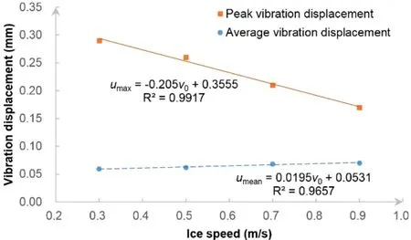
Figure 23:Vibration displacements under various ice speed
Furthermore,in order to measure the extent of ice-structure interaction,a velocity coefficient is proposed,which is defined by the ratio of ice speed and the average vibration velocity.It is found that this velocity coefficient always remains around 0.010~0.014 (Tab.7),which might be used to predict the vibration states effectively in ice-structure interaction.

Table 7:Calculation of velocity coefficient
Similarly,the quotient ofFmaxandFmeandecreases with the ratio of ice speed and thickness as well,agreeing well with Sodhi and Morris’s experimental results [Sodhi and Morris (1984)].
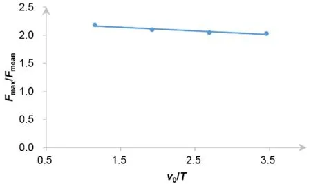
Figure 24:The ratio of maximum force to mean force Fmax/Fmean vs. the ratio of ice speed and thickness ratio v0/T
7 Conclusion
In this paper,the bond-based Peridynamics method is applied to simulate the interaction between ice and a wide vertical structure.It is shown that Peridynamics could preferably describe the crushing failure of sea ice during the interaction process.Meanwhile,numerical results obtained are found to be consistent with those calculated by DEM method,which further illustrates the effectiveness of Peridynamics in these similar scenarios.Beyond that,parameters like the diameter of vertical structure,ice thickness,and ice speed are proven to have effects on the ice-structure interaction.
(1) For the reason that both the diameter of structure and ice thickness contribute to the contact area of interaction,both of them have a positive correlation with the level of ice force and vibration displacement.
(2) Effective pressure decreases with the increasing ratio of diameter and thickness.
(3) Considering the severity of ice-structure interaction,higher ice speed would cause relatively larger ice force and higher vibration frequency,whereas the latter mainly manifesting as higher average vibration displacement but lower peak vibration displacement.
(4) Quotient of the maximum ice force and average ice force decreases with both the diameters-thickness ratio and the velocity-thickness ratio.
(5) A velocity coefficient,which is defined as the ratio of ice speed and the average vibration velocity,remains around 0.010~0.014.
Acknowledgement:This work is supported financially by the National Key R&D Program of China [2018YFC1406000,2016YFE0202700];Supported by the National Natural Science Foundation of China (NSFC) [Grant Nos.51809061,51639004];Supported by the Natural Science Foundation of Heilongjiang Province of China [LC2018021];Supported by the Fundamental Research Funds for the Central Universities [HEUCFM180111].
References
Areias,P.;Msekh,M.A.;Rabczuk,T.(2016):Damage and fracture algorithm using the screened Poisson equation and local remeshing.Engineering Fracture Mechanics,vol.158,pp.116-143.
Areias,P.;Reinoso,J.;Camanho,P.P.;César de Sá,J.;Rabczuk,T.(2018):Effective 2D and 3D crack propagation with local mesh refinement and the screened Poisson equation.Engineering Fracture Mechanics,vol.189,pp.339-360.
Bai,S.;Liu,Q.;Li,H.;Wu,H.(1999):Sea ice in the Bohai sea of China.Marine Forecasts,vol.16,no.3,pp.1-9.
Coon,M.D.;Knoke,G.S.;Echert,D.C.;Pritchard,R.S.(1998):The architecture of an anisotropic elastic-plastic sea ice mechanics constitutive law.Journal of Geophysical Research:Oceans,vol.103,no.C10,pp.21915-21925.
Coon,M.D.;Pritchard,R.S.(1974):Application of an elastic-plastic model of arctic pack ice.Proceedings of the Symposium on Beaufort Sea Coastal and Shelf Research.
Di,S.C.(2015):Discrete Element Simulation of Ice Load on Offshore Platform and Ship Hull Based on GPU Parallel Algorithm (Ph.D.Thesis).Dalian University of Technology (In Chinese).
Eranti,E.(1991):General theory of dynamic ice structure interaction with applications.Proceedings of the First International Offshore and Polar Engineering Conference,pp.489-498.
Feng,D.;Pang,S.D.;Zhang,J.(2016):Parameter sensitivity in numerical modelling of ice-structure interaction with cohesive element method.ASME 2016 35th International Conference on Ocean,Offshore and Arctic Engineering,vol.8.
Gao,Y.;Hu,Z.;Ringsberg,J.W.;Wang,J.(2015):An elastic-plastic ice material model for ship-iceberg collision simulations.Ocean Engineering,vol.102,pp.27-39.
Gu,X.;Madenci,E.;Zhang,Q.(2018):Revisit of non-ordinary state-based peridynamics.Engineering Fracture Mechanics,vol.190,pp.31-52.
Gu,X.;Zhang,Q.;Huang,D.;Yv,Y.(2016):Wave dispersion analysis and simulation method for concrete SHPB test in peridynamics.Engineering Fracture Mechanics,vol.160,pp.124-137.
Gu,X.;Zhang,Q.;Xia,X.(2017):Voronoi-based peridynamics and cracking analysis with adaptive refinement.International Journal for Numerical Methods in Engineering,vol.112,no.13,pp.2087-2109.
Hendrikse,H.(2017):Ice-Induced Vibrations of Vertically Sided Offshore Structures (Ph.D.Thesis).Delft University of Technology.
Hibler,W.D.III.(1979):A dynamic thermodynamic sea ice model.Journal of Physical Oceanography,vol.9,no.4,pp.815-846.
Huang,D.;Lu,G.D.;Qiao.P.Y.(2015):An improved peridynamic approach for quasistatic elastic deformation and brittle fracture analysis.International Journal of Mechanical Sciences,vol.94-95,pp.111-122.
Huang,Y.;Shi,Q.;Song,A.(2007):Model test study of the interaction between ice and a compliant vertical narrow structure.Cold Regions Science and Technology,vol.49,no.2,pp.151-160.
Ji,S.Y.;Di,S.C.;Li,Z.;Bi,X.J.(2013):Discrete element modelling of interaction between sea ice and vertical offshore structures.Engineering Mechanics,vol.30,no.1,pp.463-469 (In Chinese).
Ji,X.;Oterkus,E.(2016):A dynamic ice-structure interaction model for ice-induced vibrations by using van der pol equation.Ocean Engineering,vol.128,pp.147-152.
Jin,Z.;Yue,X.;Bao,Y.;Zhang,G.(1997):Relationship between tensile strength and flexural strenth and size effect on flexural strength.Advanced Ceramics,no.3,pp.29-33.
Karr,D.;Das,S.(1983):Ice strength in brittle and ductile failure modes.Journal of Structural Engineering,vol.109,no.3,pp.2802-2811.
Kry,P.R.(1978):A statistical prediction of effective ice crushing stresses on wide structures.Proceedings,4th International Association of Hydraulic Research Symposium on Ice Problems,vol.1,no.1,pp.33-47.
Kry,P.R.(1979):Implications of structure width for design ice forces.International Union of Theoretical and Applied Mechanics Symposium,pp.179-193.
Kry,P.R.(1981):Scale effects in continuous crushing of ice.International Association for Hydraulic Research,International Symposium on Ice,pp.565-580.
Liu,M.H.;Wang,Q.;Lu,W.(2017):Peridynamic simulation of brittle-ice crushed by a vertical structure.International Journal of Naval Architecture &Ocean Engineering,vol.9,no.2,pp.209-218.
Liu,R.;Xue,Y.;Lu,X.;Cheng,W.(2018):Simulation of ship navigation in ice rubble based on peridynamics.Ocean Engineering,vol.148,pp.286-298.
Lu,W.(2017):The Study of the Numerical Simulation Method of Peridynamic Based on the Bending Fracture of Sea Ice.Harbin Engineering University,China.
Macek,R.W.;Silling,S.A.(2007):Peridynamics via finite element analysis.Finite Elements in Analysis and Design,vol.43,no.15,pp.1169-1178.
Masterson,D.M.;Frederking,R.M.W.;Wright,B.;Karna,T.;Maddock,W.P.(2007):A revised ice pressure-area curve.19th International Conference on Port and Ocean Engineering Under Arctic Conditions,pp.305-314.
Madenci,E.;Oterkus,E.(2014):Peridynamic Theory and Its Applications.Springer,New York.
Matlock,H.;Dawkins,W.P.;Panak,J.J.(1969):A model for the prediction of icestructure interaction.1st Annual Offshore Technology Conference,pp.687-693.
Meng,G.(1994):Zonal analysis of design standard for compressive strength of level ice in Bohai Sea.Marine Enviormental Science,vol.13,no.2,pp.75-80.
Moslet,P.O.(2008):Medium scale ice-structure interaction.Cold Regions Science and Technology,vol.54,no.2,pp.143-152.
Parks,M.L.;Seleson,P.;Plimpton,S.J.;Silling,S.A.;Lehoucq,R.B.(2011):Peridynamics with lammps:a user guide,v0.3 beta.Sandia National Laboratory Report (2011-8253),pp.3532.
Pritchard,R.S.(1975):An elastic-plastic constitutive law for sea ice.Journal of Applied Mechanics,vol.42,no.2,pp.379-384.
Rabczuk,T.;Belytschko,T.(2004):Cracking particles:a simplified meshfree method for arbitrary evolving cracks.International Journal for Numerical Methods in Engineering,vol.61,no.13,pp.2316-2343.
Rabczuk,T.;Belytschko,T.(2007):A three-dimensional large deformation meshfree method for arbitrary evolving cracks.Computer Methods in Applied Mechanics and Engineering,vol.196,no.29-30,pp.2777-2799.
Rabczuk,T.;Zi,G.;Bordas,S.;Nguyen-Xuan,H.(2010):A simple and robust threedimensional cracking-particle method without enrichment.Computer Methods in Applied Mechanics and Engineering,vol.199,no.37-40,pp.2437-2455.
Ralston,T.D.(1977):Yield and plastic deformation in ice crushing failure.ICSI/AIDJEX Symposium on Sea Ice-Processes and Models.
Ren,H.;Zhuang,X.;Cai,Y.;Rabczuk,T.(2016):Dual-horizon peridynamics.International Journal for Numerical Methods in Engineering,vol.108,no.12,pp.1451-1476.Sanderson,T.J.O.(1988):Ice Mechanics Risks to Offshore Structures.Graham and Trotman,London,UK.
Silling,S.A(2000):Reformulation of elasticity theory for discontinuities and long-range forces.Journal of the Mechanics and Physics of Solids,vol.48,no.1,pp.175-209.
Silling,S.A.(2003):Dynamic fracture modeling with a meshfree peridynamic code.Computational Fluid &Solid Mechanics,pp.641-644.
Silling,S.A.;Askari,E.(2005):A meshfree method based on the peridynamic model of solid mechanics.Computers &Structures,vol.83,no.17-18,pp.1526-1535.
Sinding-Larsen,E.(2014):Numerical Modelling of Ice Induced Vibrations of Lock-In Type.Institutt for konstruksjonsteknikk.
Sodhi,D.S.;Morris,C.E.(1984):Ice forces on rigid,vertical,cylindrical structures.CRREL Report (US Army Cold Regions Research and Engineering Laboratory).
Wang,Q.;Wang,Y.;Zan,Y.F.;Lu,W.;Bai,X.L.et al.(2018):Peridynamics simulation of the fragmentation of ice cover by blast loads of an underwater explosion.Journal of Marine Science &Technology,vol.23,no.1,pp.52-66.
Wang,Y.M.;Yang,B.Y.;Zhang,G.Y.;Jiang,Y.C.;Zong,Z.(2017):Simulating icestructure interaction with the material point method.ASME 2017 36th International Conference on Ocean,Offshore and Arctic Engineering,vol.8.
Withalm,M.;Hoffmann N.P.(2010):Simulation of full-scale ice-structure-interaction by an extended Matlock-model.Cold Regions Science and Technology,vol.60,no.2,pp.130-136.
Ye,L.Y.;Wang,C.;Chang,X.;Zhang,H.Y.(2017):Propeller-ice contact modeling with peridynamics.Ocean Engineering,vol.139,pp.54-64.
Zhu,L.;Qiu,X.;Chen,M.;Yu,T.X.(2016):Simplified ship-ice collision numerical simulations.26th International Ocean and Polar Engineering Conference,pp.1192-1196.
 Computer Modeling In Engineering&Sciences2019年11期
- Computer Modeling In Engineering&Sciences的其它文章
- Synchronization of Robot Manipulators Actuated By Induction Motors with Velocity Estimator
- Research on Nonlinear Frequency Compression Method of Hearing Aid with Adaptive Compression Ratio
- Feature Selection with a Local Search Strategy Based on theForest Optimization Algorithm
- IDSH:An Improved Deep Su pervised Hashing Method for Image Retrieval
- Some Remarks on the Method of Fundamental Solutions for Two-Dimensional Elasticity
- A Parametric Study of Mesh Free Interpolation Based Recovery Techniques in Finite Element Elastic Analysis
