A Hybrid Local/Nonlocal Continuum Mechanics Modeling and Simulation of Fracture in Brittle Materials
Yongwei Wang ,Fei Han and Gilles Lubineau
1King Abdullah University of Science and Technology(KAUST),Physical Science and Engineering Division,COHMAS Laboratory,Thuwal,23955-6900,Saudi Arabia.
2State Key Laboratory of Structural Analysis for Industrial Equipment,Department of Engineering Mechanics,International Research Center for Computational Mechanics,Dalian University of Technology,Dalian,116023,China.
Abstract:Classical continuum mechanics which leads to a local continuum model,encounters challenges when the discontinuity appears,while peridynamics that falls into the category of nonlocal continuum mechanics suffers from a high computational cost.A hybrid model coupling classical continuum mechanics with peridynamics can avoid both disadvantages.This paper describes the hybrid model and its adaptive coupling approach which dynamically updates the coupling domains according to crack propagations for brittle materials.Then this hybrid local/nonlocal continuum model is applied to fracture simulation.Some numerical examples like a plate with a hole,Brazilian disk,notched plate and beam,are performed for verification and validation.In addition,a peridynamic software is introduced,which was recently developed for the simulation of the hybrid local/nonlocal continuum model.
Keywords:Peridynamics,hybrid model,adaptive coupling,fracture simulation,morphing function,numerical discretization.
1 Introduction
The accurate simulation of discontinuities-induced failure is still a challenge.In order to understand the mechanism of fracture,Griffith[Griffith(1921)]proposed classical fracture mechanics in the 1920s for brittle materials.It is widely used to predict the mechanical behavior of structures within the framework of local continuum mechanics.However,classical fracture mechanics is performed based on the fact that the location of a preexisting crack is known.Furthermore,it is difficult to predict the crack nucleation.
To overcome the mentioned shortcomings in classical fracture mechanics,Francfort et al.[Francfort and Marigo(1998)]developed a phase-field model in 1998.Bourdin et al.and Borden et al.[Bourdin,Francfort and Marigo (2000);Borden,Verhoosel,Scott et al.(2012)] applied the phase-field model to fracture simulation with various computational methods.Zhou et al.[Zhou,Zhuang,Zhu et al.(2018);Zhou,Zhuang and Rabczuk(2018);Zhou and Xia (2018);Zhou,Zhuang and Rabczuk (2019)] studied the crack propagation,branching and coalescence with the phase-field model.However,the phase-field method does not model the development of discontinuities,but the propagation of highly localized damage,as it is still fundamentally a continuum-field based technique.By extending the local continuum framework,the extended finite element method (XFEM) is able to explicitly introduce discontinuities [Belytschko and Black (1999)].Some researchers applied XFEM to crack propagations.However,the limitation will appear when XFEM encounters complex phenomena such as crack branching.Cundall et al.[Cundall and Strack(1979)]proposed the discrete element method(DEM),which is a mesh-free method,to analyze the crack propagation,branching and coalescence.However,fracture,obtained by DEM,has the size effect and it closely related to the size of particles.
In 2000,Silling [Silling (2000)] proposed a novel model,named peridynamics,based on integral equilibrium equations.Since integral equations are mathematically compatible with discontinuities,peridynamics can handle the crack initiation and propagation without introducing a complicated failure criterion [Kilic,Agwai and Madenci (2009)],and Ha et al.[Ha and Bobaru (2010);Wang,Oterkus and Oterkus (2018);Shou,Zhou and Berto (2019);Ren,Zhuang and Rabczuk (2016);Rabczuk,Ren and Zhuang(2019)] have successfully applied it to fracture simulations.However,peridynamics suffers from a high computational cost because a point in peridynamics is interacting with numerous points in a finite neighborhood,which results in the expensive computation of the resultant of forces.To overcome the disadvantage of the expensive computation,some improvements have been developed.Ren et al.[Ren,Zhuang and Rabczuk (2017)] proposed a dual-horizon peridynamic model in which the variable horizon is used instead of a constant horizon.Macek et al.[Macek and Silling (2007);Kilic and Madenci (2009);Liu and Hong(2012);Seleson,Beneddine and Prudhomme(2013);Lubineau,Azdoud,Han et al.(2012);Han and Lubineau (2012);Shojaei,Mudric,Zaccariotto et al.(2016);Shojaei,Mossaiby,Zaccariotto et al.(2018);Fang,Liu,Fu et al.(2019);Wang,Kulkarni and Tabarraei(2019)]proposed to couple peridynamics with classical continuum mechanics for reducing the computational cost.Macek et al.[Macek and Silling (2007)] and Kilic et al.[Kilic and Madenci(2009)] coupled peridynamics with classical continuum mechanics by satisfying kinematic compatibility over an overlap zone where both peridynamics and classical continuum mechanics co-exist.Liu et al.[Liu and Hong (2012)] bridged peridynamics and classical continuum mechanics by an interface element.In the interface element,the static admissibility is satisfied.Seleson et al.[Seleson,Beneddine and Prudhomme(2013)]proposed a force-based coupling scheme,which is also based on static admissibility.Lubineau et al.[Lubineau,Azdoud,Han et al.(2012)] proposed the morphing approach which linked the nonlocal and local continuum mechanics based on the constraint of energy equivalence.Obviously,the equivalent material parameters between peridynamics and classical continuum mechanics are critical factors for guaranteeing a successful coupling.
Compared with other coupling methods,the morphing approach,proposed by Lubineau et al.,established a constraint equation of stiffness which naturally guaranteed the equivalence of material parameters between peridynamics and classical continuum mechanics.The morphing technique is also easy to implement from a technical point of view because it fully relies on spatial modifications of the material parameters,which is easy to control.
Based on the morphing approach,a hybrid local/nonlocal continuum model was developed to couple bond-based peridynamics with classical continuum mechanics [Lubineau,Azdoud,Han et al.(2012)].The hybrid model makes use of a priori function to indicate the nonlocal subdomain for peridynamics.This nonlocal subdomain is in charge of crack initiations and propagations.The hybrid model is compatible with the traditional boundary conditions,for instance,surface tractions.This hybrid model is also used to couple ordinary state-based peridynamics with classical continuum mechanics [Han,Lubineau,Azdoud et al.(2016)].Additionally,Han et al.[Han,Lubineau and Azdoud (2016)] also coupled bond-based peridynamics with damage mechanics by this hybrid model.
In 2014,Azdoud et al.[Azdoud,Han and Lubineau (2014)] presented an approach to adaptively update the peridynamic subdomain according to the evolution of a crack with a three-dimensional(3D)benchmark example.Based on it,this paper further describes this adaptive coupling algorithm for the hybrid model in detail.Then a validation example under a non-homogeneous deformation is investigated for the effectiveness of the hybrid model.After the validation,we simulate several two-dimensional (2D) numerical examples to display its efficiency and performance for fracture simulations.In addition,a peridynamic software was introduced.The software was recently developed to apply the hybrid model with the adaptive coupling approach to fracture simulations.
The remainder of this paper is organized as follows:Section 2 reviews bond-based peridynamics and the hybrid local/nonlocal continuum model;Section 3 describes a process of applying the hybrid model to the adaptive simulation of crack propagations;Section 4 introduces a software which was developed to implement the hybrid model,and validates the hybrid model with this software in a bi-dimensional example under non-homogeneous deformation;and some benchmark numerical examples are displayed to predict crack initiations and propagations in Section 5.
2 Model description
2.1 Bond-based peridynamics
In 2000,Silling [Silling (2000)] proposed peridynamics which is one kind of nonlocal model.In peridynamics,the equilibrium equation at pointxfor a quasi-static problem is expressed as

whereHδ(x) is the neighborhood of pointxandδis the horizon.bis the external body force.f(p →x)is the bond force such that


where the relative position vectorξ=p-xis called bond.ηis the relative displacement vector andC[x](ξ) is the micromodulus tensor,which are defined as follows [Silling(2000)],

wherec[x](ξ)is the coefficient function,anduis the displacement.
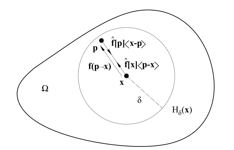
Figure 1:The nonlocal continuum Ω and the partition of the interaction,f(p →x),into partial interactions
2.2 Bond failure
In peridynamics,when the bond stretchsis larger than a critical value,scrit,the bond will break in an irreversible manner[Silling and Askari(2005)].This failure law has been widely used for fracture simulations [Ha and Bobaru (2010);Azdoud,Han and Lubineau(2014);Hu,Ha and Bobaru(2012)].

The failure law is implemented by introducing a history-dependent scalar-valued functionµ(t,ξ)into the bond force[Silling and Askari(2005)].µ(t,ξ)is defined as follows,

wheret′andtdenote the computational steps.Note that the critical bond stretch,scrit,is considered as an intrinsic material parameter.
2.3 A hybrid local/nonlocal continuum model
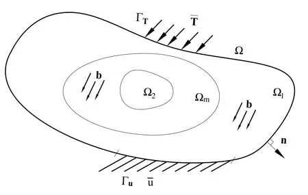
Figure 2:The subdomains Ω1,Ω2 and Ωm
One disadvantage of peridynamics is the high computational cost.In order to overcome this issue,Lubineau et al.[Lubineau,Azdoud,Han et al.(2012)]developed a hybrid model to couple peridynamics with classical continuum mechanics.In the hybrid model,let the domain Ω be the overall domain.It can be divided into three subdomains:Ω1,Ω2and Ωm[Lubineau,Azdoud,Han et al.(2012)].Ω = Ω1∪Ω2∪Ωm,Ω1∩Ω2=∅,Ω1∩Ωm=∅and Ω2∩Ωm=∅(see Fig.2).The idea of the hybrid model is that there is only classical continuum mechanics in the subdomain Ω1while there is only peridynamics in the subdomain Ω2.However,both classical continuum mechanics and peridynamics are defined in the morphing subdomain Ωm.The displacementis applied on the boundary Γuof∂Ω,and the external surface tractionis imposed on the boundary ΓTof∂Ω.nis the outward direction that is normal to ΓT.
In this paper,we focus on homogeneous,isotropic and linearly elastic materials under small deformation.The hybrid model based on the unified governing equations over Ω can be built as follows:
□Kinematic admissibility and compatibility:

□Static admissibility:

□Constitutive equations:

whereεis the infinitesimal strain tensor,σis the Cauchy stress tensor.E(x)is the stiffness tensor.
Usingc0(ξ) as a reference,let us redefineC[x](|ξ|) by introducing a priori function,α(0≤α(x)≤1)such that

αis also called morphing function.Comparing Eq.(5)with Eq.(15),we can obtain thatc[x](ξ)=α(x)c0(ξ).
According to the constraint of energy density conservation,with assumptions of a small perturbation and a homogeneous deformation over the neighborhood,the stiffness tensor,E(x),at any pointxcan be expressed with the morphing function as follows [Lubineau,Azdoud,Han et al.(2012)],

When one pointxwith its neighborhood is located in the peridynamic subdomain,one can know thatE(x)=0 andα(p)=1∀p ∈Hδ(x).Thus the relation betweenE0andc0(ξ)can be obtained according to Eq.(16).
Remark.Now the accurate definitions of Ω1,Ω2and Ωmcan be given byαas follows,

3 The adaptive algorithm for simulation of crack propagations
In this section,we will describe the process of implementing the hybrid model for the adaptive simulation of crack propagations.
3.1 Initially introducing peridynamic subdomain
To study the crack initiations and propagations,it is necessary to introduce a peridynamic subdomain,i.e.,Ω2,before implementing the adaptive hybrid model.The peridynamic subdomain,which is used for fracture,should cover the zone where cracks will firstly initiate.One feasible approach for assigning the initial peridynamic subdomain is that one can take the zone undergoing strong deformation gradients[Lubineau,Azdoud,Han et al.(2012)]during the elastic stage as the potential zone for crack initiations.For complicated structures,the zone under strong gradients can be obtained by calculating the deformation gradient field in advance.
According to Eq.(18),we introduce the peridynamic subdomain by assigning a zone withα= 1.This paper takes advantage of the circular zone with a radiusr1,centered onx0which is designated as a flag point.Over the circular zone,we assign the morphing function,α(x)=αx0(x)=1,∀x ∈{x||x-x0|≤r1}.Meanwhile,adjacent to the circular zone,we assign an annular zone with an inner radiusr1and an outer radiusr2,centered onx0,where 0<αx0(x)<1,∀x ∈{x|r1<|x-x0| <r2}.The morphing function of the remaining part of the structure is set asαx0(x) = 0,∀x ∈{x||x-x0| ≥r2}.Note thatr1andr2are scalars,andr2>r1.
After assigning the distribution of the morphing function,according to Eq.(18),we can obtain the initial distribution of peridynamic subdomain,Ω2.Meanwhile,Ω1and Ωmare also obtained.
3.2 Discretization of the hybrid model
After introducing the peridynamic subdomain,we now focus on numerically carrying out the hybrid model by the finite element method (FEM).The principle of minimum potential energy is used to solve the problem,and the potential energy of the overall domain combining classical continuum mechanics and peridynamics can be written as follows[Azdoud,Han and Lubineau(2014);Han,Lubineau,Azdoud et al.(2016)],

where

After we discretized and minimized the potential energy,a linear algebraic equation set can be derived for finite element computations as follows,

where{d}is a vector of all the nodal displacements,

[ξ⊗ξ][Nj(p)Rj -Ni(x)Ri]dVpdVxand

where[·]and{·}denote a matrix and a vector.nis the number of the total elements,h(x)is the number of the relative elements of pointx,[N]is the matrix of shape function,[H]denotes a matrix of differential operators and[R]is a diagonal matrix in which the diagonal entries may be 0 or 1,depending on the nodes of one element.Note that all these definitions are the same to that of FEM.
At the discretization level,the subdomains Ω1and Ωmare meshed by the finite element(FE) while Ω2is meshed by the discontinuous Galerkin finite element (DGFE) which was successfully applied to peridynamics by Azdoud et al.[Azdoud,Han and Lubineau(2014);Chen and Gunzburger(2011)].In DGFE,each element does not share nodes with other elements and the DGFEs are connected by bonds that are defined by the relative position between quadrature points of elements.Consequently,the crack initiations and propagations are driven by bond breaking through the boundaries of elements.
3.3 Adaptive expansion of the peridynamic subdomain
When bonds begin to break,the peridynamic subdomain adaptively expands by introducing new peridynamic zones.The new peridynamic zones should cover these broken bonds and ensure that crack tips always stay far away from the boundary of the peridynamic subdomain.This paper introduces new peridynamic zones at the centroids of damaged elements in which at least a bond breaks,by assigning zones withα= 1.Note that the centroids of damaged elements are designated as flag points.
Fig.3 is a diagrammatic sketch that helps illustrate the process of the adaptive expansion.In the beginning,an initial peridynamic subdomain was assigned at some pointx0.When one bond in the peridynamic subdomain breaks,two new circular peridynamic zones are introduced at the centroids of damaged elements,x1andx2.The new peridynamic zone,centered on the flag pointx1,is introduced by assigningαx1(x)=1,∀x ∈{x||x-x1|≤ri},and the morphing function at the adjacent zone is set as 0<αx1(x)<1,∀x ∈{x|ri <|x-x1| <ro}.Meanwhile,we can define the other peridynamic zone which is centered on the flag pointx2,by assigningαx2(x) = 1,∀x ∈{x||x-x2| ≤ri},and the morphing function at the adjacent zone is defined as 0<αx2(x)<1,∀x ∈{x|ri <|x-x2| <ro}.Note thatriandroare scalars,andro >ri.Now considering all the flag points in the structure,the morphing function,α,for any pointpyields the following rule,
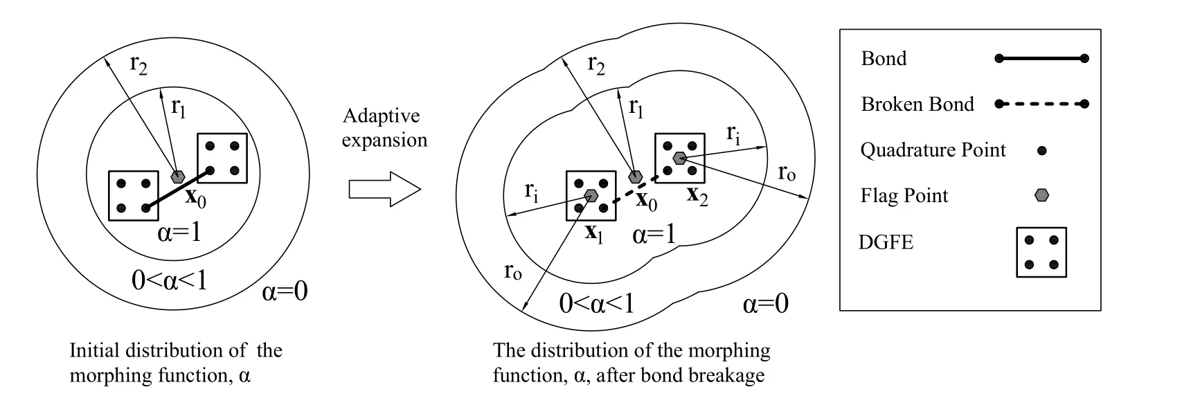
Figure 3:Bond breaking induces adaptive expansion of the peridynamic subdomain.Note that not all the bonds are shown

With this adaptive approach,the peridynamic subdomain,Ω2,can be driven by broken bonds automatically without identifying crack tips.

Figure 4:Transfer from FE to DGFE and crack initiation.Note that not all the bonds are shown
At the discretization level,the update of the peridynamic subdomain results in an update of mesh which leads to some elements transferring from FE to DGFE by inserting nodes for the new transferred elements,and all DGFEs are available for crack initiations and propagations (see Fig.4).Note that the freedom of solution will increase after inserting new nodes for DGFEs.
3.4 Flowchart of the adaptive algorithm
Fig.5 defines the implicit algorithm for the adaptive simulation of crack propagations.In the adaptive algorithm,the boundary conditions are specified asNprogressive increments.For one given increment,the structure is meshed by FE and DGFE to assign the peridynamic subdomain firstly.Next,the linear equations are solved,and the displacement results are used to calculate the stretch of bonds which is used for updating broken bonds.If a bond is decided to fail,the stiffness matrix that this broken bond contributed previously needs to update.Then the linear equations will be solved iteratively until there is no new bond failure.
After that,the adaptive algorithm will choose and store the new flag points that are the centroids of new damage elements in which a bond was broken at the given increment,and there was no bond breakage in previous increments.Then the same increment is carried out again.
If no new damage element appears,the algorithm will go to the next increment until the last loading increment is completed.Note that in this algorithm,the update of the peridynamic subdomain is performed between increments rather than iterations in each increment.
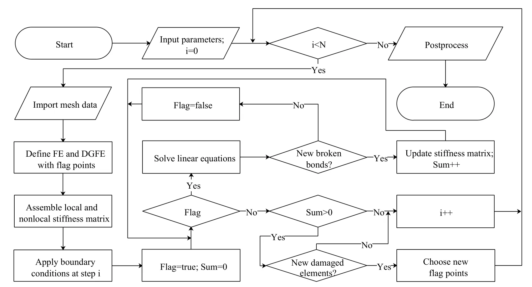
Figure 5:A flowchart of the adaptive algorithm for the hybrid model,where N is the number of total progressive increments
4 Validation study
Lubineau et al.[Lubineau,Azdoud,Han et al.(2012)] presented some examples under homogeneous deformations to show the accuracy of the hybrid model in which the stiffness constraint(see Eq.(16))of the morphing subdomain is built based on an assumption of a homogeneous deformation over the neighborhood.Thus,it is interesting and necessary to validate the hybrid model for non-homogeneous deformations,even if the stiffness constraints in the morphing subdomain are used far from strong gradients [Lubineau,Azdoud,Han et al.(2012)].In this section,a 2D numerical example for which we assume plane stress,under non-homogeneous deformations,is carried out by a platform that is based on the hybrid model,and ANSYS that is based on classical continuum mechanics,respectively.

Figure 6:The structure and its initial distribution of the morphing function
4.1 A brief introduction of PeriFem for implementing the hybrid model
To make the hybrid model with an adaptive algorithm available for implementation,a software with a friendly user interface,named PeriFem,including solving,pre- and post-processing modules is developed.In the pre-processing module,we can make use of the software to generate a geometric model,mesh the model,input material parameters,and apply boundary conditions.In addition,the software can also take advantage of mesh data from other software,such as ANSYS and GMSH.In the solving module,the algorithm is developed by the C++ language,and it can implement 2D and 3D simulations.In the post-processing module,the software can display the synchronous calculation results for every increment.It is convenient for the users to use the mouse and keyboard to check the contour results.Also,it is very simple to display the contour results of the inner parts of a 3D model by a slicing technique.Additionally,the users can also output all the calculation data and store them in files.
4.2 Case description
A homogeneous sample is studied to validate the hybrid model.The geometric parameters and boundary conditions of the structure are shown in Fig.6(a).The left boundary of the plate is fixed inxdirection,and the middle point of the left boundary is also fixed inydirection.The displacement condition is applied to the right boundary inxdirection with= 2 mm.Both the top and bottom of the plate are free.This numerical example implements bilinear quadrilateral elements in a finite element framework.The grid size Δxof elements is 1.5 mm.
The stiffness parameters for classical continuum mechanics including Poisson’s ratio and Young’s modulus areν= 1/3 andE= 30 GPa,respectively.The horizon,δ,of the neighborhood in peridynamics is 4.5 mm.The coefficient of micromodulus,c0(ξ),is assumed to be an exponential function,

whereτ0is a constant,which is calculated according to the Poisson’s ratio and Young’s modulus.lis a characteristic length which is determined to guaranteee-δ/lapproaching 0.Here,lis set to be 0.5 mm in this example.
To implement the hybrid model in the simulation,an initial seed of peridynamic subdomain is necessary.The initial peridynamic subdomain is seeded in the center of the hole withr1= 25 mm andr2= 45 mm see Fig.6(b).In the orange zone,α= 1 while in the blue zone,α=0.αdecreases from 1 to 0 in the rainbow zone.
Note that the span of the rainbow zone influences the error (i.e.,ghost forces for the energy-based coupling).Actually,the error is driven byδ/Lc[Lubineau,Azdoud,Han et al.(2012)],whereLcis the span of the rainbow zone(i.e.,Lc=r2-r1in this paper).Ifδis given,the error reduces asLcbecomes larger.
4.3 Results analysis

Figure 7:Contour of the displacements by PeriFem and ANSYS (unit of displacement:m).Note that the legend sort of(a)and(b)is different from that of(c)and(d)
The displacement fields calculated by PeriFem and ANSYS are shown in Fig.7.The displacement fields inxdirection are in good agreement by comparing Fig.7(a) and Fig.7(c),while Fig.7(b) and Fig.7(d) display a high similarity of displacements inydirection.
To exactly illustrate the accuracy of the hybrid model,the displacements by PeriFem and ANSYS on three cutting lines are depicted and compared in Fig.8 and Fig.9 which also exhibit a good agreement.After calculating the relative error of displacements in the three cutting lines,we can find that the maximum relative error of the displacement inxdirection is 1.43% for cutting line 1,and the maximum relative error of the displacement inydirection is 3.96% for cutting line 2.The maximum relative error of cutting line 3 inxandydirections are 0.5% and 1.5%,respectively.Note that the relative error is defined bywhereupis the displacement calculated by the PeriFem whileuais the displacement calculated by ANSYS.

Figure 8:The displacements of cutting line 1 and cutting line 2
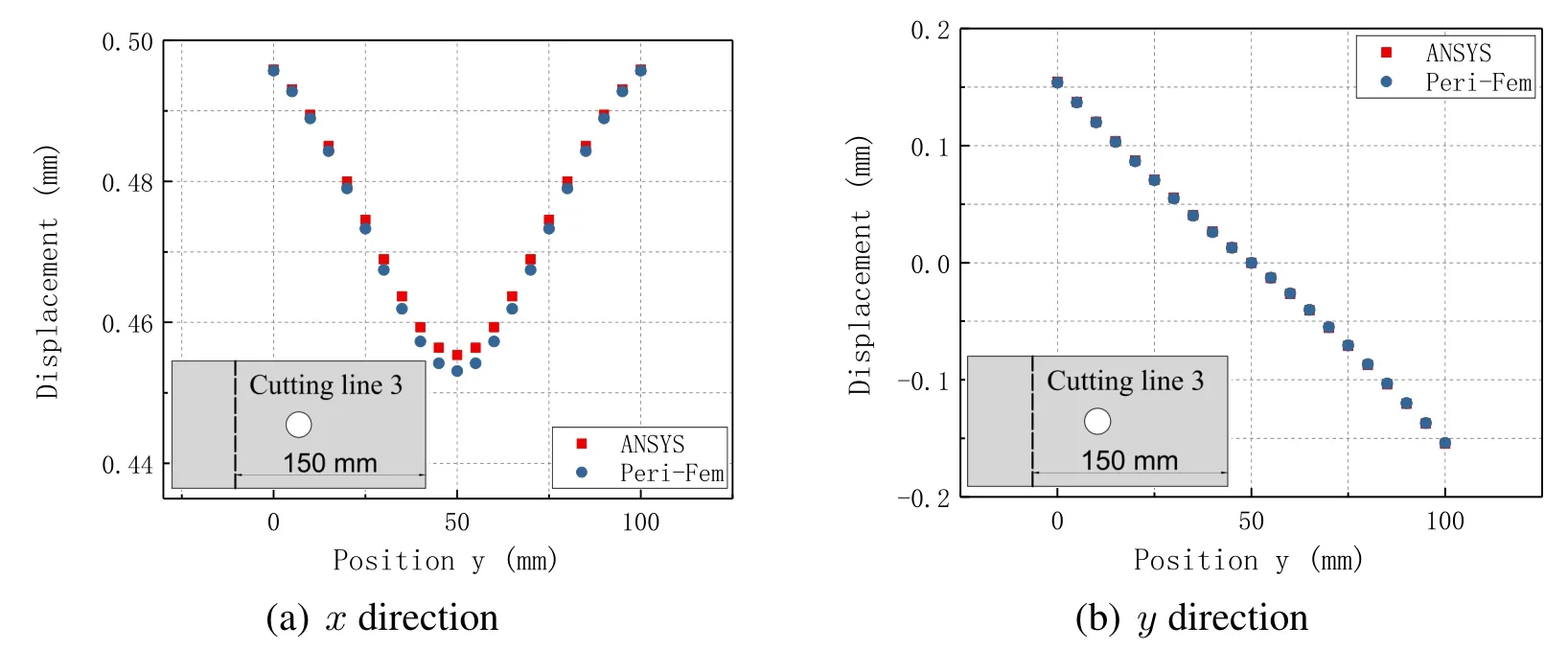
Figure 9:The displacements of cutting line 3
The results from two different approaches are in good agreement,and the comparison illustrates the accuracy of the hybrid model for non-homogeneous deformations.
5 Application of the hybrid model to fracture simulations
This section makes use of the hybrid model to predict crack initiations and propagations.The following 2D numerical examples aim at illustrating the performance of the hybrid model on fracture simulations.
All the samples are assumed to be linear and elastic,and the 2D samples under plane stress are meshed by bilinear quadrilateral elements.Poisson’s ratios for 2D analysis isν=1/3.The coefficient of micromodulus,c0(ξ),is defined in Eq.(24).The horizon,δ,of the neighborhood in peridynamics is chosen as 3Δx.
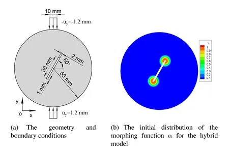
Figure 10:The structure and its initial distribution of the morphing function
5.1 Brazilian disk
The Brazilian disk containing a single crack was experimentally tested by Haeri et al.[Haeri,Shahriar,Marji et al.(2014)] to study the breakage process of the disk.In this example,we apply the hybrid model to studying the properties of Brazilian disk under compression.The boundary conditions and dimensions of the sample are illustrated in Fig.10(a).The grid size of elements is Δx=0.5 mm.The Young’s modulusEis 3.1 GPa andl= 0.1 mm.In the simulation,two seeds of the initial peridynamic subdomain are centered around the crack tips withr1=4 mm andr2=8 mm see Fig.10(b).The critical stretch,scrit,is set to be 0.055.This simulation is performed in 100 progressive increments(steps)so that the increment of displacement yields=0.012 mm in each step.
From simulation results (see Fig.11),it is validated that the hybrid model can simulate the whole process of the elastic deformation,crack initiations and propagations,and the structure failure.Fig.11 including six loading steps,exhibits the failure process and the contour of damage which is defined by Silling et al.[Silling and Askari(2005)].There is no crack at Step 83(Fig.11(a))while crack suddenly appears at step 84(Fig.11(b)).Then the crack grows slowly until Step 89 at which the crack propagates further.A disastrous fracture suddenly appears at Step 92.From the figures,we can find that the fractures initiate from the pre-crack tips and propagate toward the direction of loading points.The failure path of the disk by the hybrid model is very similar to the experimental result(Fig.6(c))in Haeri et al.[Haeri,Shahriar,Marji et al.(2014)].
Note that the grids shown in Figs.11,14,15,18 and 21 are DGFEs where peridynamics is performed.As the crack propagates,the DGFEs adaptively update.From the simulation,we can find that peridynamics is always restricted to a relatively small zone,compared to the whole structure,which can highly reduce the computational cost.
Fig.12(a)displays the load-displacement curve of the resultant force on the upper loading boundary.Fig.12(b) is an enlargement of the curve in the red box of Fig.12(a).The load-displacement curve is approximately linear before Step 83.Zooming in on the peak region shows that the resultant of the forces encounters some drops.With the help of Fig.11,we can pinpoint that the force experiences a small drop when the crack appears at Step 84,and another small drop is encountered at Step 89 when the crack propagates further.The drastic drop of the force at Step 92 keeps in step with the disastrous fracture.From Fig.11(f),we find that there are still connections in the disk,which accounts for the residual bearing capacity after Step 92.
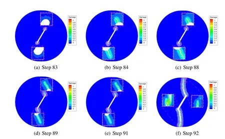
Figure 11:Simulation of the crack initiation and propagation.Note that the magnification of subfigure in Figs.(a)(b)and(c)is 35 while that of Figs.(d)(e)and(f)is 15
5.2 A notched plate with an off-center circular hole

Figure 12:Load-displacement curves of the Brazilian disk
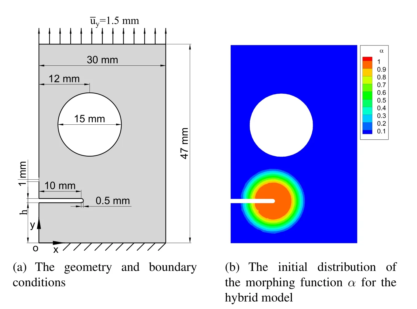
Figure 13:The structure and its initial distribution of the morphing function
We apply the hybrid model to simulating a notched plate with an off-center circular hole under unilateral tension.This test has been simulated by various investigators[Dipasquale,Zaccariotto and Galvanetto(2014);Tabiei and Wu(2003);Ni,Zhu,Zhao et al.(2018)]for predicting the crack initiations and propagations.The boundary conditions and dimensions of the sample are illustrated in Fig.13(a).The grid size of elements is Δx=0.25 mm.The Young’s modulus is 71.4 GPa andl= 0.05 mm.In the simulation,one seed of the initial peridynamic subdomain,centered around the notch tip withr1= 4 mm andr2= 8 mm,is introduced (see Fig.13(b)) to cover the strong deformation gradient zone.The critical stretch,scrit,is set to be 0.1.This simulation is performed in 200 progressive increments(steps)so that the increment of displacement yields=0.0075 mm.Two examples withh=10 mm andh=15 mm are performed to predict the paths of the crack propagations.The simulation results are presented in Figs.14 and 15.Three diagrams related to different loading steps for each distancehare presented to display the process of crack initiations and propagations which are similar to the results reported by Dipasquale et al.[Dipasquale,Zaccariotto and Galvanetto(2014)],Tabiei et al.[Tabiei and Wu(2003)]and Ni et al.[Ni,Zhu,Zhao et al.(2018)].By comparing Fig.14 and Fig.15,we can conclude that different distances between the notch and the hole can induce different paths of crack propagations.Additionally,the simulation results also display the adaptive expansion of the peridynamic subdomain.
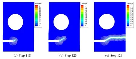
Figure 14:Simulation of the crack initiation and propagation for h=10 mm

Figure 15:Simulation of the crack initiation and propagation for h=15 mm
Fig.16 displays the curves of resultant forces on the top of the plate versus the displacement,which reflect the fracture process in the test.For the specimen withh= 10 mm,the load-displacement curve is approximately linear before the displacement reaches 0.88 mm.Then the force drops,which corresponds to the crack appearance(see Fig.14(a)).After that,the force encounters a drastic drop,which corresponds to the crack splitting the structure(see Fig.14(c)).For the specimen withh= 15 mm,the force experiences a drop,which corresponds to the crack appearance(see Fig.15(a)).Then the force grows up.The force encounters another drop,which corresponds to the crack reaching the hole(see Fig.15(c)).Since the structure is not destroyed in this simulation,it still has a relatively large residual bearing capacity.

Figure 16:Load-displacement curves of the notched plate with an off-center circular hole
5.3 A notched beam under four-point bending
This numerical example is a four-point bending test of a single-edge notched beam.The boundary conditions and dimensions of the sample are illustrated in Fig.17(a).The grid size of elements is Δx=0.5 mm.The Young’s modulus is 30 GPa andl=0.1 mm.In the simulation,one seed of the initial peridynamic subdomain,centered around the notch tip withr1= 4 mm andr2= 6 mm,is introduced(see Fig.17(b)).The critical stretch,scrit,is set to be 0.05.This simulation is performed in 100 progressive increments(steps)so that the increment of displacement yields=0.02 mm in each step.
Fig.18 exhibits the crack propagation associated with the damage evolution.The crack initiates at Step 81,and after several steps,the crack grows rapidly to about 21 mm.The crack under four-point bending is almost straight.The small curve in the fracturing path is induced by the unstructured mesh.In Fig.18,the adaptive expansion of the peridynamic subdomain always covers the crack tip and is consistent with the crack propagation.
Fig.19 displays the curves of the forces on the loading points of the beam versus the displacement,which reflect the brittle fracture in the test.The curves approximate linear before a drastic drop.The drastic drop corresponds to the sudden appearance of the long crack (see Fig.18(b)).The stairs of the load-displacement curves are induced by crack propagations.The two load-displacement curves are consistent until the displacement reaches 1.88 mm.The branching of the two curves appears due to the asymmetry of the structure which is induced by the crack propagation(see Fig.18(d)).
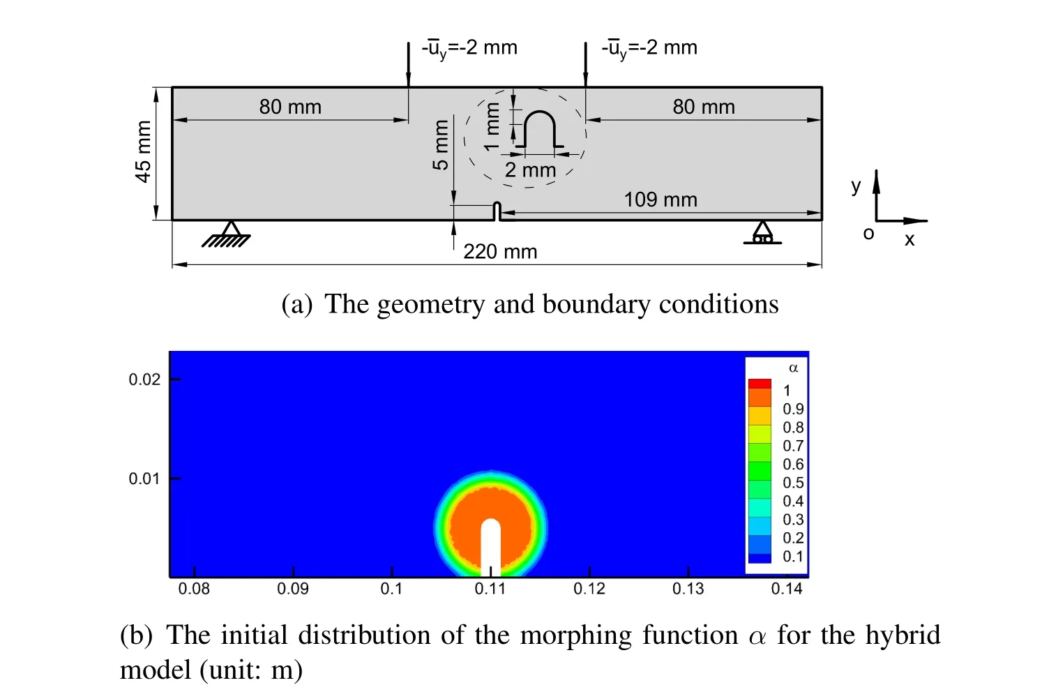
Figure 17:The structure and its initial distribution of the morphing function

Figure 18:Simulation of the crack initiation and propagation (unit:m).Note that the magnification of subfigure in Fig.(a)is 10
5.4 A double-edge-notched plate

Figure 19:Load-displacement curves of the notched beam

Figure 20:The structure and its initial distribution of the morphing function
Here,we simulate a plate which is notched in the middle of both left and right sides[Nooru-Mohamed,Schlangen and van Mier(1993);Liu and Hong(2012);Han,Lubineau and Azdoud (2016);Zhou,Rabczuk and Zhuang (2018)].Its boundary conditions and dimensions are illustrated in Fig.20(a).The grid size of elements is Δx= 1 mm.The Young’s modulus is 30 GPa andl= 0.2 mm.In the simulation,two seeds of the initial peridynamic subdomain are centered around the notch tips withr1= 8 mm andr2= 16 mm(see Fig.20(b)).The critical stretch,scrit,is set to be 0.1.This simulation is performed in 50 progressive increments(steps).In each step,=0.08 mm and=0.02 mm.Fig.21 is the simulation results that display the evolution of the damage and fracture.The damage and fracture initiate from each notch tip and propagate towards the opposite notch.In the beginning,the crack which is initiated from the left notch tends to the bottom of the plate while another crack tends to the upper.This kind of fracture path is induced by the asymmetric boundary conditions.Later the crack tips form a neck-zone where shear deformations deflected the evolution of the cracks.The proceeding evolution finally brings the upper crack tip into contact with the lower crack,which eventually leads to the failure of the plate.In addition,the adaptive expansion of the peridynamic subdomain is always restricted to a relatively small zone as the cracks propagate,which can make the simulation much more efficient.

Figure 21:Simulation of the crack initiation and propagation.Note that the magnification of subfigure in Fig.(a)is 20

Figure 22:Load-displacement curves of the double-edge-notched plate
Fig.22 displays the curves of resultant forces on the upper and left loading boundaries versus the displacement.From the figure,we can find that the drastic drops of the forces at Step 20 lead to a small residual bearing capacity of the structure.We can conclude that the sudden appearance of the crack at Step 20 (see Fig.21) is a deadly fracture for this structure.
6 Conclusion
In this paper,the hybrid local/nonlocal continuum model is introduced,and the adaptive coupling approach is described in detail.Firstly,for the purpose of validation,a plate with a circular hole is simulated by the hybrid model and the classical continuum mechanics.The simulation shows that the results from both models are in good agreement,and the relative errors of the cutting lines are less than 3.96%.This validation illustrates the accuracy of the hybrid model under non-homogeneous deformations.Secondly,this paper applies this hybrid model to fracture simulations.Various numerical examples such as a Brazilian disk,a notched plate with a hole,a notched beam and a double-edge-notched plate are simulated to predict complicated crack initiations and propagations.The simulation results exhibit that (i) the hybrid model can simulate the whole process of the elastic deformation,crack initiations and propagations,and the structure failure,(ii) the process of the adaptive expansion of the peridynamic subdomain which is always restricted to a relatively small zone displays the efficiency of the hybrid model.Thirdly,the peridynamic software,PeriFem,also displays its performance through the numerical example.
Acknowledgement:The authors gratefully acknowledge the financial support received from KAUST baseline,the National Natural Science Foundation (11872016) and the Fundamental Research Funds of Dalian University of Technology (Grant No.DUT17RC(3)092) for the completion of this work.
 Computer Modeling In Engineering&Sciences2019年11期
- Computer Modeling In Engineering&Sciences的其它文章
- Synchronization of Robot Manipulators Actuated By Induction Motors with Velocity Estimator
- Research on Nonlinear Frequency Compression Method of Hearing Aid with Adaptive Compression Ratio
- Feature Selection with a Local Search Strategy Based on theForest Optimization Algorithm
- IDSH:An Improved Deep Su pervised Hashing Method for Image Retrieval
- Some Remarks on the Method of Fundamental Solutions for Two-Dimensional Elasticity
- A Parametric Study of Mesh Free Interpolation Based Recovery Techniques in Finite Element Elastic Analysis
