Experimental study of an insert and its influence on churning losses in a high-speed electro-hydrostatic actuator pump of an aircraft
Junhui ZHANG, Ying LI, Bing XU,*, Min PAN, Qun CHAO
a The State Key Laboratory of Fluid Power and Mechatronic Systems, Zhejiang University, Hangzhou 310027, China
b Department of Mechanical Engineering, University of Bath, Bath BA2 7AY, United Kingdom
KEYWORDS
Abstract The speed of an Electro-Hydrostatic Actuator (EHA) pump can recently reach 20000 r/min,and its churning losses increase obviously with an increasing speed,which results in low efficiency and thus increasing heat in aircraft EHA systems.In order to reduce churning losses at high speeds,more attention should be given to the design of an insert.In this paper,the effect of an insert with different design parameters on churning losses is investigated through Computational Fluid Dynamics(CFD)simulation and experiments by calculating the difference between churning losses torques of the test pump with and without the insert based on a high-speed churning losses test rig.Analytical results show that the gap between the insert and the cylinder is critical for churning losses reduction.It is found that the churning losses of the test pump can be reduced with a decreasing gap between the cylinder block and the insert at high speeds.This is because the insert can decrease the turbulence occurrence at high speeds. The results can be used for flow field analysis and optimization of the high-speed EHA pump and provide a new method for improving efficiency of high-speed EHA pumps.
1. Introduction
Compared to an electric drive system,a fluid transmission system has some inherent advantages such as high power density and high reliability.1Currently, axial piston pumps have been widely used for fluid power transmission systems such as mining construction machinery,2automobiles, and aircraft.3,4For example, axial piston pumps are usually used in EHA systems to control flight control surfaces in aircraft as shown in Fig.1.5In order to improve the power density of EHA systems which is important to aircraft,many methods have been proposed to increase the pressure and rotational speed of axial piston pumps.6However,power losses of axial piston pumps increase significantly with increases of speed and pressure due to increases of friction and leakage. Power losses in axial piston pumps not only reduce the power density, but also increase the heat of aircraft EHA systems.7An increase of heat in aircraft EHA systems can increase the thermal deformation of mechanical components, accelerate the oxidation of the oil,and even lead to a breakdown of the system.Therefore,studies on the energy saving of axial piston pumps in aircraft EHA systems are of great significance.
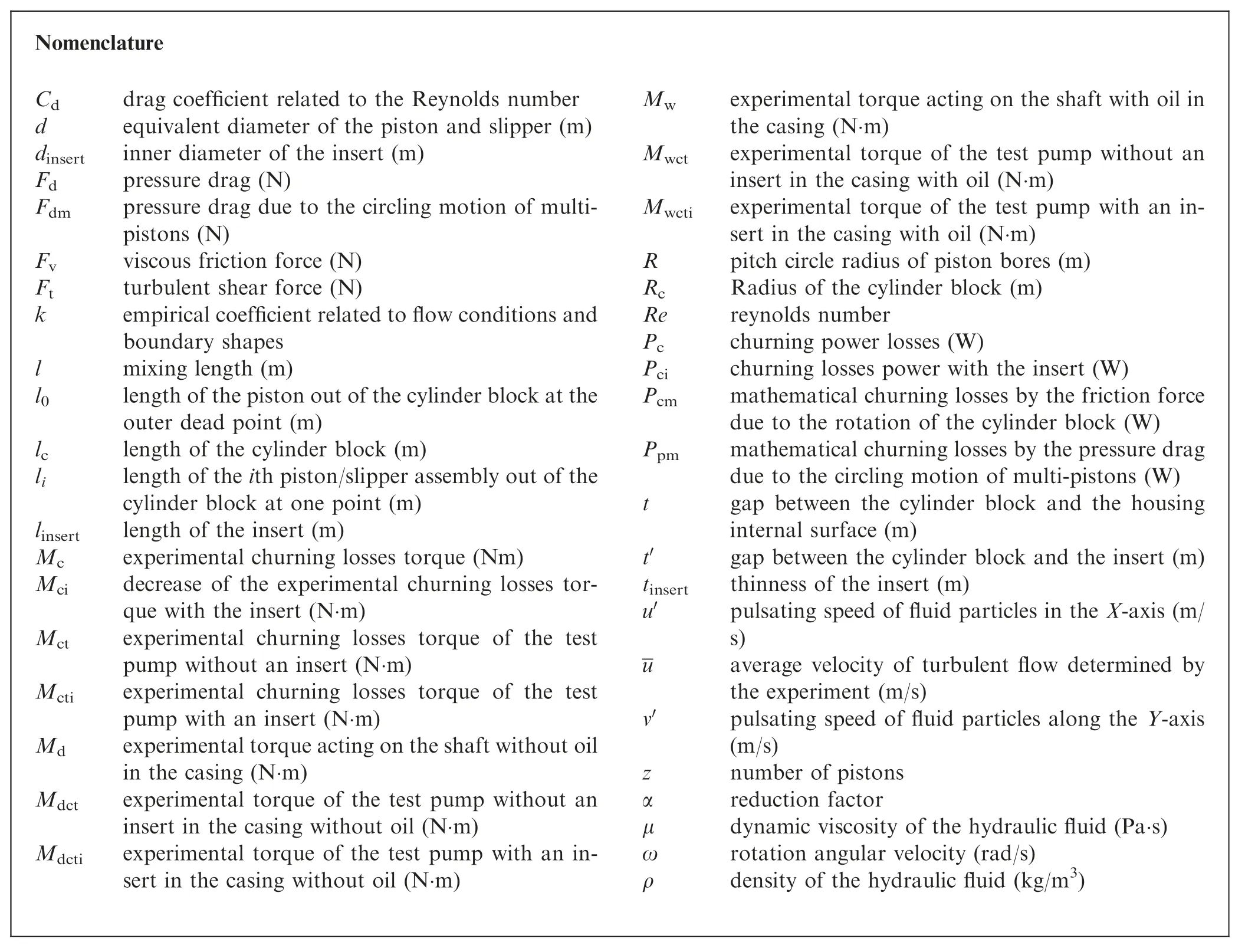
Nomenclature Cd drag coefficient related to the Reynolds number d equivalent diameter of the piston and slipper (m)dinsert inner diameter of the insert (m)Fd pressure drag (N)Fdm pressure drag due to the circling motion of multipistons (N)Fv viscous friction force (N)Ft turbulent shear force (N)k empirical coefficient related to flow conditions and boundary shapes l mixing length (m)l0 length of the piston out of the cylinder block at the outer dead point (m)lc length of the cylinder block (m)li length of the ith piston/slipper assembly out of the cylinder block at one point (m)linsert length of the insert (m)Mc experimental churning losses torque (Nm)Mci decrease of the experimental churning losses torque with the insert (N·m)Mct experimental churning losses torque of the test pump without an insert (N·m)Mcti experimental churning losses torque of the test pump with an insert (N·m)Md experimental torque acting on the shaft without oil in the casing (N·m)Mdct experimental torque of the test pump without an insert in the casing without oil (N·m)Mdcti experimental torque of the test pump with an insert in the casing without oil (N·m)Mw experimental torque acting on the shaft with oil in the casing (N·m)Mwct experimental torque of the test pump without an insert in the casing with oil (N·m)Mwcti experimental torque of the test pump with an insert in the casing with oil (N·m)R pitch circle radius of piston bores (m)Rc Radius of the cylinder block (m)Re reynolds number Pc churning power losses (W)Pci churning losses power with the insert (W)Pcm mathematical churning losses by the friction force due to the rotation of the cylinder block (W)Ppm mathematical churning losses by the pressure drag due to the circling motion of multi-pistons (W)t gap between the cylinder block and the housing internal surface (m)t′ gap between the cylinder block and the insert (m)tinsert thinness of the insert (m)u′ pulsating speed of fluid particles in the X-axis (m/s)u average velocity of turbulent flow determined by the experiment (m/s)v′ pulsating speed of fluid particles along the Y-axis(m/s)z number of pistons α reduction factor μ dynamic viscosity of the hydraulic fluid (Pa·s)ω rotation angular velocity (rad/s)ρ density of the hydraulic fluid (kg/m3)
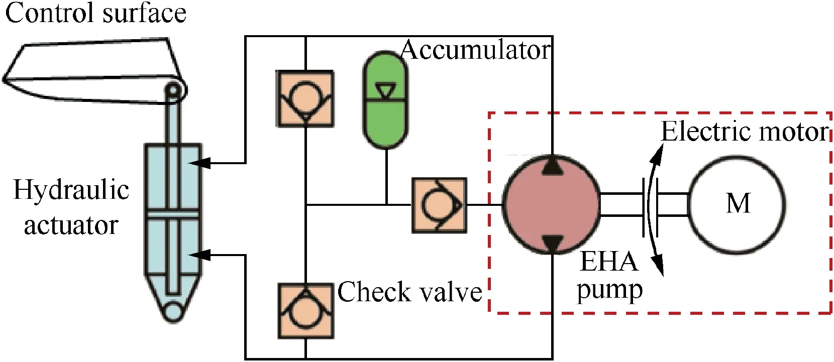
Fig. 1 Schematic of an EHA system.
Fig. 2 shows the configuration of a high-speed EHA pump consisting of several pistons within a common cylindrical block. The pistons are nested in a circular array within the block at equal angular intervals about the centerline of the cylinder block. The piston heads are mounted in the slippers which are under the limitation of the retainer mechanism.The swash plate forces the pistons to reciprocate periodically within the cylinder block,changing the volume of the displacement chamber and realizing the suction and discharge of fluid through the valve plate.The EHA pump is operated in the oilfilled casing,and the air in the casing is discharged through the exhaust valve of the EHA pump before the EHA pump starts.
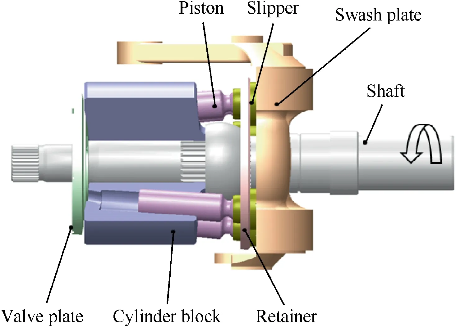
Fig. 2 Configuration of a high-speed EHA pump.
Power losses in a high-speed EHA pump mainly include volumetric loss, mechanical loss, and churning loss. The volumetric loss is caused by the leakage flow, and the mechanical loss is caused by the friction. The churning loss is due to the resistance caused by the internal rotating components churning in the oil-filled casing.Theoretical and experimental studies have been published on approaches to reduce volumetric losses and mechanical losses in axial piston pumps. The main focus was on the design of the piston/cylinder block pair, the slipper/swash plate pair, and the cylinder block/valve plate pair to reduce the friction and leakage. For example, Murrenhoff et al.8-10and Ivantysynova et al.11,12showed that some special surface treatments such as coating, surface texturing, and micro-surface shaping pistons could reduce the friction and leakage of the piston/cylinder block pair in axial piston pumps.Hooke et al.13,14and Yamaguchi et al.15-17presented the design criteria for the optimum size of the slipper in axial piston pumps to achieve the minimum power loss, maximum load-carrying capacity, and maximum moment stiffness of the slipper/swash plate pair. Manring and Zhang18and Xu et al.19presented some methods such as a valve plate with a trapped-volume region and a high-machining precision cylinder block, in order to decrease extra cylinder tilting moments and leakage of the cylinder block/valve plate pair in axial piston pumps.
In the last few decades,lots of methods have been proposed to improve the efficiency of a piston pump in terms of its volumetric and mechanical losses. However, few studies have been focused on the churning loss of an axial piston pump.This is because the churning loss is negligible for a pump with a nominal speed between 1500 r/min and 3000 r/min. However, a high power density leads to increasing speeds of axial piston pumps. The proportion of churning losses gradually increases especially for pumps applied in the field of aerospace.20For example, EHA pumps manufactured by Messier-Bugatti can be driven at a rotational speed up to 15000 r/min.21Similarly,EHA pumps applied for F-35(Lockheed Martin F-35 Lightning II) by Parker Hannifin can be operated at a rotational speed up to 20000 r/min.22For axial piston pumps with such high speeds, the churning loss due to the stirring of rotating components in the oil-filled casing is no longer negligible. Therefore, special attentions should be given to churning losses in axial piston machines. It can be found from previous studies that churning losses are mainly caused by the viscous friction force due to the rotation of the cylinder block and the pressure drag caused by the circling motion of the pistons and slippers in the oil-filled casing.The viscous friction force Fvand the pressure drag Fdare given by23-25

where μ is the dynamic viscosity of the hydraulic fluid,ω is the rotation angular velocity,Rcis the radius of the cylinder block,lcis the length of the cylinder block, t is the gap between the cylinder block and the housing internal surface,Cdis the drag coefficient related to the Reynolds number,26ρ is the density of the hydraulic fluid, R is the pitch circle radius of piston bores,d is the equivalent diameter of the piston and slipper, z is the number of pistons, and liis the length of the ith piston/slipper assembly out of the cylinder block at one point.
The churning losses studied in these models show that the pistons and slippers in an axial piston pump have a higher influence on the churning losses than that of the cylinder block due to the square term of velocity (ω2). Thus, these methods were mainly developed to reduce the churning loss due to the circling pistons and slippers in axial piston pumps. One of the methods on churning loss reduction described by Rahmfeld et al.27was a dry bent-axis motor with a 5000-r/min rotational speed. However, the inevitable friction from three friction pairs (piston/cylinder block pair, slipper/swash plate pair, and cylinder block/valve plate pair) will generate much heat due to the absence of oil lubrication cooling. Another method to reduce the churning loss was the power boost insert proposed by the company Parker Hannifin28and Murrenhoff et al.29,30as shown in Fig. 3.
It should be noted that Eq. (1) is presented under the assumption of laminar flow. However, this assumption may be not suitable because the Reynolds number is increased with an increasing speed as shown in Re=ωRctρμ-1in axial piston pumps.31,32Churning losses produced by the rotating cylinder block may be higher than those by the pistons and slippers due to the turbulent flow, and churning losses with an insert studied in these theories only showed that the insert could reduce the churning losses due to the circling motion of the pistons and slippers. The effects of the insert on churning losses due to the rotation of the cylinder block and the design of the insert were ignored.Therefore,this paper aimed to analyze the effect of an insert on the reduction of churning losses due to the cylinder block. It also identified the critical parameters of the insert which are sensitive to reduce the churning losses.Experimental work was carried out to validate the theoretical results of the proposed design criteria of the insert.
2. Estimation of churning losses
The theoretical model of churning losses can be divided into low-speed laminar flow and high-speed turbulent flow as shown in Fig. 4. Eq. (1) presents churning losses caused by the viscous friction force due to the rotation of the cylinder block under the assumption of laminar flow, and the friction force due to the rotation of the cylinder block consists of a turbulent shear force Ftcaused by the exchange of fluid momentum as

where v′is the pulsating speed of fluid particles along the y-axis, and u′is the new pulsating speed of fluid particles in the x-axis.
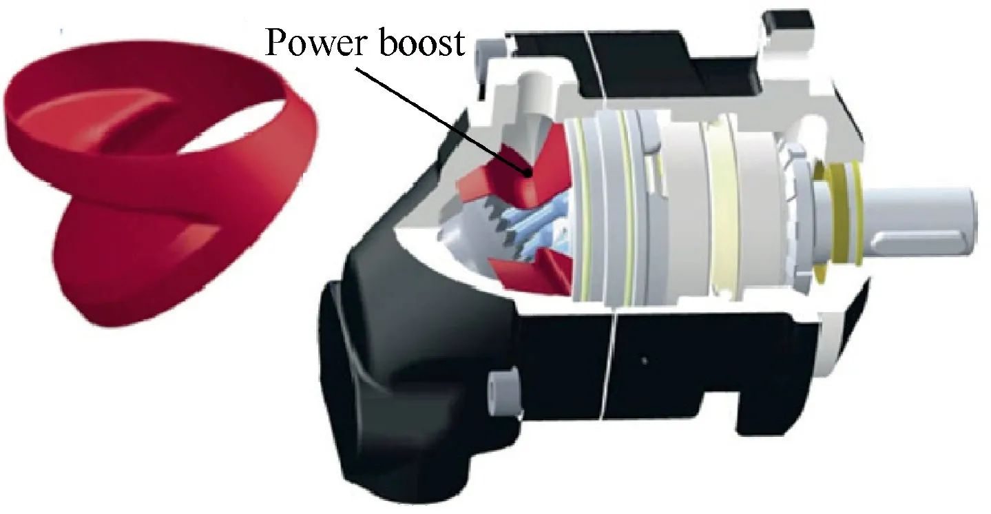
Fig. 3 Configuration of an insert.28
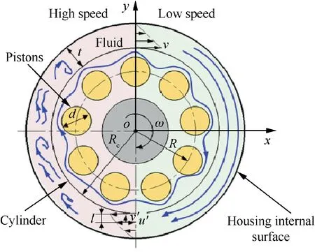
Fig. 4 Schematic representation of churning losses in a highspeed EHA pump.
According to Prandtl’s mixing-length theory, the pulsating speed of the fluid particles can be written as

It remains to be noted that Eq. (2) ignores the effect of the covering among pistons in a high-speed EHA pump. A reduction factor is defined in the pressure drag around the multipistons,31-35because the cover effect of the circling flow among multi-pistons and the occurrence of the cavitation phenomenon in the fluid flow outside the multi-pistons lead to a decrease of the fluid flow velocity and the pressure drag among the multi-pistons. The pressure drag Fdmdue to the circling motion of the multi-pistons should be written as

where α is the reduction factor.
The expressions for the churning losses caused by the friction force and pressure drag due to the rotation of the cylinder block and the circling motion of multi-pistons in a high-speed EHA pump are given by

The rotation of the cylinder block has a greater influence than that of the circling motion of the multi-pistons on churning losses with an increasing speed in a high-speed EHA pump,because the turbulent shear force on the cylinder block is much higher than the pressure drag when a reduction factor exists among pistons.24The churning losses can be reduced effectively if the turbulent shear force can be reduced, because the turbulent power is much higher than the laminar power due to the cube of velocity as shown in Eq.(6).From the mathematical models,it can be seen that the diameter and length of the cylinder as well as the fluid viscosity are determined by the pump displacement and operating conditions. Only the gap between the cylinder block and the housing internal surface can be optimized, and the Reynolds number is decreased with a decreasing gap between the cylinder block and the housing internal surface as shown in Re=ωRctρμ-1in a high-speed EHA pump.24Churning losses can be effectively decreased if the occurrence of the turbulent flow can be delayed by decreasing the Reynolds number. This paper experimentally investigates the effect of an insert on reducing churning losses in terms of the turbulent flow, focusing on the churning losses produced by the rotating cylinder block at low and high speeds.
3. Experimental methods
Churning losses are usually calculated by measuring the torque difference between the dry casing and the wet casing in highspeed EHA pumps.27However,it is difficult to analyze churning losses directly using a high-speed EHA pump because it is difficult to segregate the influence of the friction losses on the torque measurement. To overcome the limitation of friction losses among friction pairs,a novel test rig is designed for measuring the churning losses of a high-speed EHA pump in the State Key Laboratory of Fluid Power and Mechatronic Systems at Zhejiang University.31The test rig is composed of an electric motor (YGP-7.5 kW, range 0-16,000 r/min), a torque-speed sensor (JN338, range 0-10 N·m, accuracy±0.2%; range 0-16000 r/min), a temperature sensor(NEXON TA3020/C50-600/242N12M011D6, range -50-600°C, accuracy±0.2%), a pressure sensor (Huba 520.932 S033401, range 0-25 bar, accuracy±0.3%), and a test pump as shown in Fig. 5.
The net churning torque losses can be measured by the torque difference between with and without oil in the casing.The churning power losses can be deduced using the following equation:

where Mcis the experimental churning losses torque,Mwis the experimental torque acting on the shaft with oil in the casing,and Mdis the experimental torque acting on the shaft without oil.
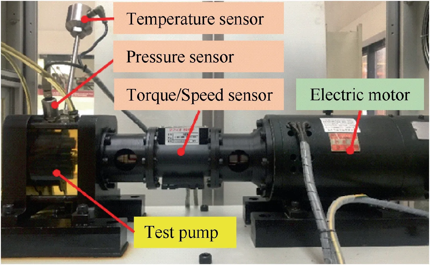
Fig. 5 Churning losses test rig.
The decrease of churning losses with the insert can be calculated by calculating the difference between the churning losses torque of the test pump with and without the insert.The decrease of the churning losses power with the insert Pcican be expressed as

where Mciis the decrease of the experimental churning losses torque with the insert,Mctiis the experimental churning losses torque of the test pump with the insert,Mctis the experimental churning losses torque of the test pump without the insert,Mwctiis the experimental torque of the test pump with the insert in the casing with oil, Mdctiis the experimental torque of the test pump with the insert in the casing without oil,Mwctis the experimental torque of the test pump without the insert in the casing with oil, and Mdctis the experimental torque of the test pump without the insert in the casing without oil.
The effects of the insert on churning losses can be obtained by the experimental results of Eq. (9). This new measurement method also raises some challenges. The first challenge is the design of the insert (including the insert length and diameter).Fig. 6 shows the 3D view of the insert and the frontal crosssection of the test pump.The insert is composed of a cylindrical sleeve, a mounting surface, and a separating surface. Fig. 6(a)also shows that there are several symmetrical arcs on the separating surface for the screws installation and positioning. The separating surface is used to increase the stability of the insert under the high-velocity impact of the oil, and it also helps to isolate the oil outside the cylinder and pistons. The separating surface is aligned with the end surface of the cylinder block to ensure the length of the insert as shown in Fig. 6(b). The diameter of the insert cannot be too big due to the space limit;however, a thin insert wall will increase viscous friction losses due to the small t(see Eq.(1)).Therefore, inserts are designed for three different diameters, and the gaps between the insert and the cylinder block are 1 mm,3 mm,and 5 mm,respectively.The thickness of the insert is 2 mm ensuring the strength of the insert and less influence on the power density in a high-speed EHA pump. Table 1 shows the geometric dimensions of the investigated test pump and the insert.
The other challenge is that it is difficult to segregate the influence of friction losses of friction pairs on the insert in a high-speed EHA pump. Because the churning losses are obtained by measuring the torque difference between the dry and wet casings, the friction losses torque of the friction pairs will inevitably affect the measured torque, especially the dry friction torque of the friction pairs in the casing without oil.Thus, we redesigned the test pump (Fig. 6(b)) in such a way that the measuring system had only the piston/cylinder pair and the insert was fixed on the coverplate for space reason.The other non-rotating parts, such as the swash plate and the valve plate, were ignored because their influences on the churning losses were very small. The pistons were fixed on the cylinder block through specific screws, and the fixed pistons only rotated in the test pump without a reciprocating motion. The dimensions of the pistons were the same as those of the pistons immersed in the real pump oil-churning parts.
4. Results
Experiments were carried out with a shaft speed from 0 to 15000 r/min at a temperature of 35°C. The casing pressure was 1.02 bar based on a high-speed EHA pump prototype used for aircraft.36Experimental results are presented at constant pressure and temperature for various speeds to analyze the influence of the insert comprehensively.
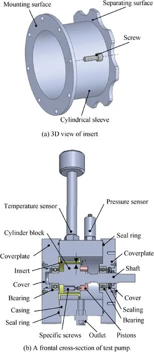
Fig. 6 3D view of the insert and cross-section of the test pump.
Fig. 7 shows the experimental results of churning losses with and without an insert at various speeds.Compared to that of the test pump with an insert, the churning losses torque in the test pump is smaller for the test pump without an insert at low speeds as shown in Fig.7(a).The churning losses torque increases with a decreasing gap between the insert and the cylinder block. This can be explained by the fact that the viscous friction losses in the first term of Eq.(6)are the dominant factors of the churning losses in the low-speed laminar flow.Thus, the churning losses torque in the test pump with an insert is higher than that of the test pump without an insert due to a reduction of the gap between the cylinder block and the insert t′, and the smaller gap between the insert and the cylinder block, the higher the churning losses torque by the Newton inner friction law. Fig. 7(b) also shows that the increase of the churning losses power with an insert at low speeds is due to an increase of viscous friction losses with an increasing t′as shown in Eq.(6). However, it is not significant because the viscous friction losses are small in the low-speed laminar flow. Meanwhile, the pressure drag losses due to the pistons have a greater influence than the viscous friction losses on churning losses at low speeds.
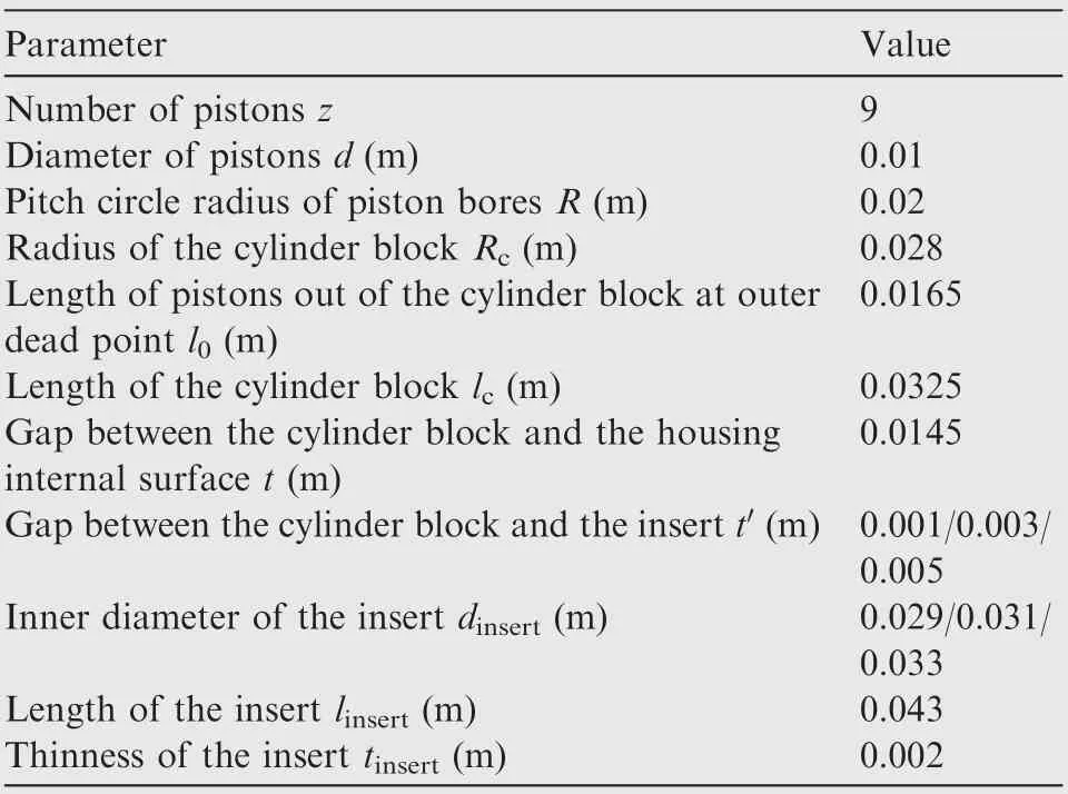
Table 1 Geometric dimensions of the investigated test pump and the insert.
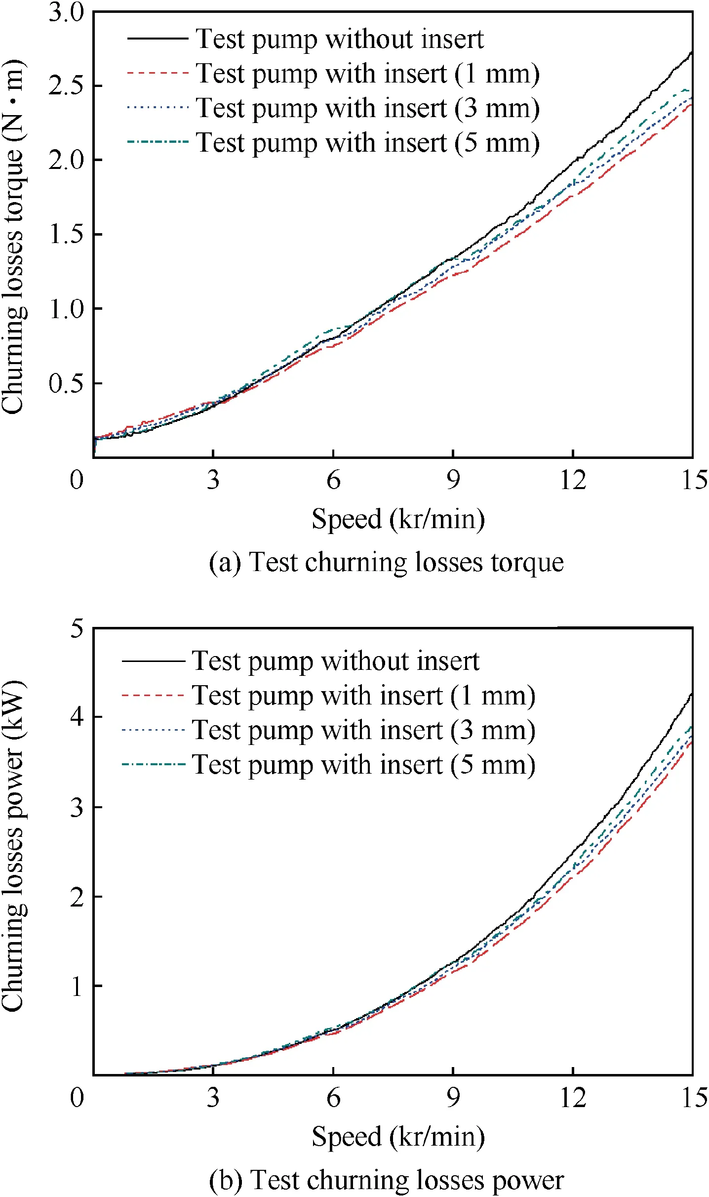
Fig. 7 Experimental results of the insert at various speeds.
Fig. 7(a) also shows that the churning losses torque in the test pump with an insert is smaller in comparison with the results of the test pump at high speeds,because the flow states change from laminar flows to turbulent flows with an increase of the speed.Moreover,the rotation of the cylinder block has a greater influence than the circling motion of multi-pistons on churning losses with an increasing speed in a high-speed EHA pump, because a reduction factor exists among pistons and the turbulent shear force is much higher than the viscous friction force on the cylinder block. The proportion of turbulent friction losses in the second term of Eq. (6)increases with an increasing speed.
The slope of Fig.8 decreases in the test pump with an insert because of a reduction of the Reynolds number,and the churning losses torque decreases with a decrease of the gaps between the insert and the cylinder block. In addition, three different gaps of an insert are investigated, and the churning losses torque can be reduced with an increased gap of the insert at low speeds as shown in Fig.7(a),because the velocity gradient can be reduced in the term of laminar viscous friction losses. On the contrary, the churning losses torque can be reduced with a decreased gap t′at high speeds. An explanation is that the critical speed of the turbulent flow is increased with the gap of the insert decreased as shown in Fig. 8. It indicates that the insert can delay the turbulence occurred, and the loss of additional turbulent shear stress is significantly reduced. It is also shown in Fig. 9 that there is a difference in the fluid condition at two different speeds of the test pump and the test pump with a 1-mm gap of the insert.The flowing area is small and regular at low rotational speeds in both the test pump and the test pump with a 1-mm gap of the insert as shown in Fig.9(a) and (c). Meanwhile, the flowing area outside the cylinder block in the test pump is significantly increased and tends to be more disordered at high speeds than those in the test pump with a 1-mm gap of the insert as shown in Fig.9(b)and(d).In order to explain this phenomenon, a CFD simulation model for the test pump was established.Fig.10 shows the simulation results of the fluid turbulent kinetic energy for different speeds.It can be seen that the turbulent kinetic energy increases obviously with an increasing speed as shown in Fig. 10(a) and (b),and the insert can effectively reduce the turbulent kinetic energy in the fluid outside the cylinder block at high speeds as shown in Fig. 10(b) and (d).
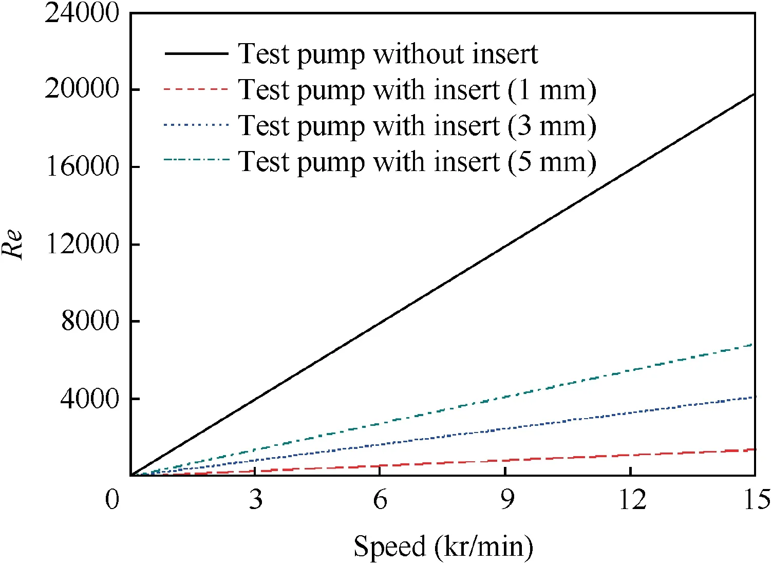
Fig.8 Comparison of the Reynolds number with and without an insert at various speeds.
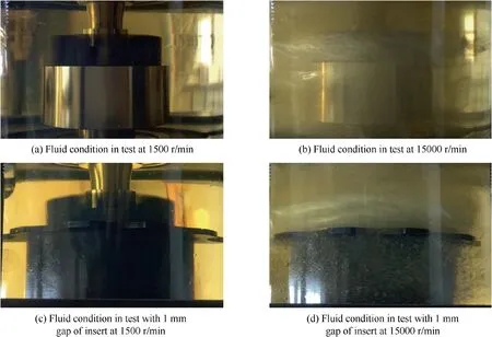
Fig. 9 Fluid conditions at various speeds.
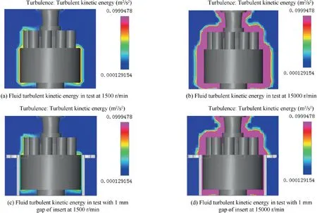
Fig. 10 Fluid turbulent kinetic energy for different speeds.
Therefore, a reduction of the gap t′between the cylinder block and the insert can effectively reduce the churning losses in a high-speed EHA pump because it usually operates at a high speed and a low pressure during take-off and landing of an aircraft. A reduction of the gap between the cylinder block and the casing can also directly reduce the churning losses,but the oil for heat dissipation is not enough in the case. Fig. 11 shows the temperature rises for different test pumps at 15000 r/min in one minute. It can be seen that the internal oil volume of the test pump is decreased by 1.16×10⁻⁵m3after adding the pistons, while the temperature rise increased by about 5°C. The internal oil volume of the test pump decreased by 3.2×10⁻⁵m3after adding the 1-mm gap of the insert,while the churning losses decreased and the temperature rise increased by about 2°C. Thus, in order to obtain a 1-mm gap between the inner casing and the cylinder block which is the same as that in the test pump with a 1-mm gap of the insert, the internal oil volume in a high-speed EHA pump should be decreased by 1.2×10⁻⁴m3. The temperature rise will be increased significantly.
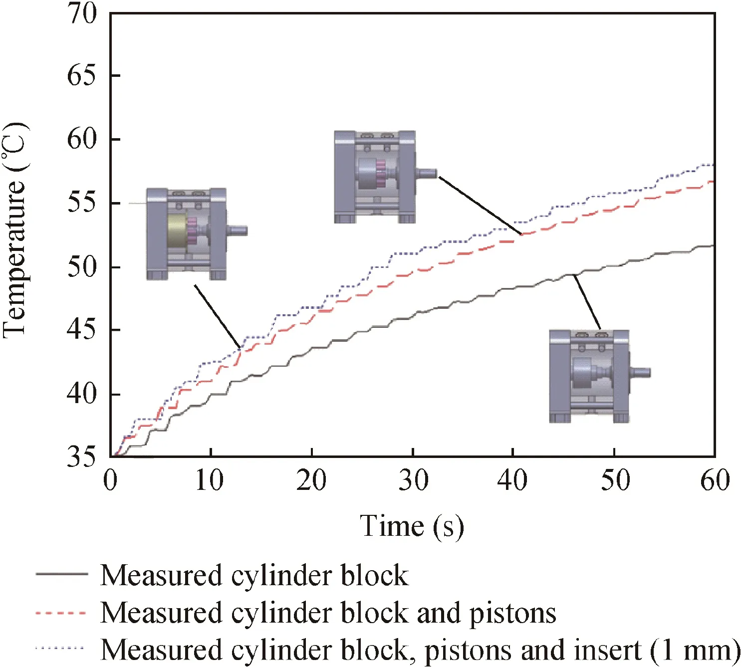
Fig. 11 Temperature rises of different test pumps at 15000 r/min.
Therefore, the insert can effectively reduce the churning losses at high speeds. The smaller clearance of the insert at high speeds, the better effects of reducing the churning losses in the test pump.
5. Conclusions
In this paper, the effect of an insert on reducing churning losses due to the cylinder block is investigated in a highspeed EHA pump. Studies on the insert have shown that:
Firstly, the reduction of churning losses with the insert increases with an increasing speed.Thus,the insert can reduce the churning losses of the test pump especially at high speeds.Secondly,the churning losses can be reduced with a decreased gap of the insert at high speeds, because the critical speed of turbulent flow is increased with a decreased gap of the insert.Thirdly, the churning losses can be reduced with an increased gap of the insert at low speeds, because of a reduction of the velocity gradient in laminar viscous friction losses.
Future work will investigate approaches such as using nano-coating to reduce friction forces and churning losses at both low and high speeds based on this test rig.
Acknowledgements
The authors would like to thank financial supports from the National Basic Research Program of China (973 Program)(No.2014CB046403) and the National Natural Science Foundation of China (No. 1737110).
 CHINESE JOURNAL OF AERONAUTICS2019年8期
- CHINESE JOURNAL OF AERONAUTICS的其它文章
- Special Column of BWB Civil Aircraft Technology
- Assessment on critical technologies for conceptual design of blended-wing-body civil aircraft
- Exploration and implementation of commonality valuation method in commercial aircraft family design
- Effects of stability margin and thrust specific fuel consumption constrains on multi-disciplinary optimization for blended-wing-body design
- Nacelle-airframe integration design method for blended-wing-body transport with podded engines
- On developing data-driven turbulence model for DG solution of RANS
