Nacelle-airframe integration design method for blended-wing-body transport with podded engines
Zhenqing XIN, Zhenli CHEN,*, Wenting GU, Gng WANG,Zhogung TAN, Dong LI, Binqin ZHANG
KEYWORDS
Abstract Strong shock waves and flow separation often occur during the integration of nacelle and airframe for blended-wing-bodies with podded engines.To address this problem,this paper presents an integration method with numerical simulations.The philosophy of channeling flow and avoiding the throat effect on the nacelle and airframe is established based on the analysis of flow interference in the initial configuration. A parametric integration design method is proposed from twodimensional plane to three-dimensional space with control mechanisms and selection principles of the key parameters determined by their influences. Results show that strong shock waves and flow separation can be successfully eliminated under the influence of both the reshaped channel and decelerated inflow below the nacelle. Supersonic regions around the nacelle are effectively reduced, concentrating mainly on the lip position. Thus, a significant cruise drag reduction(8.7%) is achieved though the pressure drag of the nacelle increases.
1. Introduction
Flow interference between an engine and airframe has an important impact on aircraft performance. In traditional configurations,power systems are usually mounted under the wing or at the rear fuselage;therefore,the nacelle,pylon and wing/-body are easily coupled with strong shock waves, which may induce serious flow separation.1-3This unfavorable effect can be effectively eliminated by adjusting influencing factors such as nacelle positions and component contours.4,5A successful case is Boeing 737-300.6
As a promising layout for future civil aircraft,the Blended-Wing-Body (BWB) configuration has received considerable attention.7-11Its engines, different from those of the traditional aircraft, are usually podded above the body or embedded in the airframe with Boundary Layer Ingestion (BLI).Relevant studies demonstrated the serious flow interference.12,13For embedded engines, the ingesting boundary layer can result in low total pressure recovery and excessive inlet distortion. Moreover, strong shock waves and flow separation may occur in the flow channel formed between adjacent nacelles. Adopting podded engines can reduce or even avoid BLI, but coupling problems remain for different components with aerodynamic performance tightly related.
In view of the above problems, engine-airframe integration is regarded as an important topic in the projects of Ultra Efficient Engine Technology (UEET)14and Environmentally Responsible Aviation (ERA)15,16sponsored by NASA. The open literature is rather limited. Rodriquez17performed a CFD-based optimization for the BWB configuration with BLI engines to reduce drag and improve inlet pressure recovery while holding distortion at a fixed level. Campbell et al.18used Constrained Direct Iterative Surface Curvature(CDISC)method to eliminate shock waves and flow separation in the flow channel between adjacent nacelles. For the configuration with podded engines, flow separation caused by nacelleairframe interference was eliminated by optimizing the airframe shape.12These are mainly optimization studies with high complexity and computational costs. In addition, the influences of design variables and flow mechanisms have not been completely revealed.
According to aerodynamics, flow interference is closely associated with contours and relative locations of components.Serious problems can occur due to the strong shock waves caused by channel effect, especially between a nacelle and airframe. If an engine is powered on, the situation will become worse because of inlet spillage. Thus, a BWB configuration with podded engines is proposed in this paper, featured by nacelle-airframe integration.The flow interference in the initial configuration is analyzed, and then the design philosophy of flow channeling and a method for parameter matching are proposed.Control mechanisms and selection principles of the key parameters are given based on their influences.Results show a significantly reduced drag, and the characteristics of the flow field are analyzed.
2. Configuration and numerical methods
2.1. Research model and mesh
The initial configuration NPU-BWB-300 of this study is designed by Northwestern Polytechnical University based on the optimized result of Ref.19. This unpowered configuration consists of a blended wing body and two nacelles of high bypass ratio turbofans, as shown in Fig. 1. The parameters of this configuration are listed in Table 1.
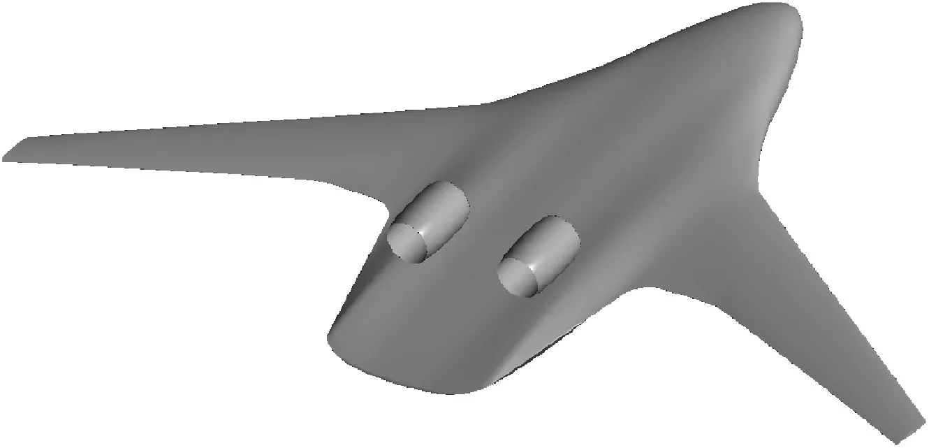
Fig. 1 NPU-BWB-300 configuration.
For this BWB layout, the nacelle is designed to minimize the intensity of the supersonic region near the lip.The position of the nacelle is determined by an initial investigation into the placement effect to achieve better performance. Typically, the nacelle should be positioned with a suitable onset Mach number of local inlets while maintaining an adequate distance from the body trailing edge to shield engine noise. To attenuate the interference effect on a contracting rear body, the nacelle axis is aligned to the local airframe contour with a 3° tilt angle.
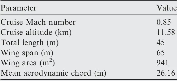
Table 1 Parameters of NPU-BWB-300.
Before the numerical simulations, multiblock structured grids with H-H topology are generated for the right semispan of the BWB configuration which contains approximately 6 million cells. An O-mesh is applied, surrounding the surface of the configuration.The points near the walls are started with the first cell height in a boundary layer set to y+of 1 to meet calculation requirements.The stretching ratio of the boundary layer in the direction normal to all solid surfaces is specified to less than 1.2 and the far-field boundary distance is set to approximately 20 mean aerodynamic chords from the aircraft.For the critical flow regions such as the zone below the nacelle,more grids are applied to better capture flow details.The girds of the research model can be seen in Fig. 2.
2.2. Numerical method and validation
The flow computations are carried out by solving high fidelity Reynolds Averaged Navier-Stokes(RANS)equations with the finite volume approach. A second-order central difference method is used to discretize viscous terms.The time discretization is completed with an implicit algorithm. The turbulence viscosity terms are specified by Shear Stress Transport (SST)turbulence model to effectively capture shock waves and flow separation. Free flow conditions are assigned to the far field surface, and no-slip boundary conditions are employed on all solid surfaces.
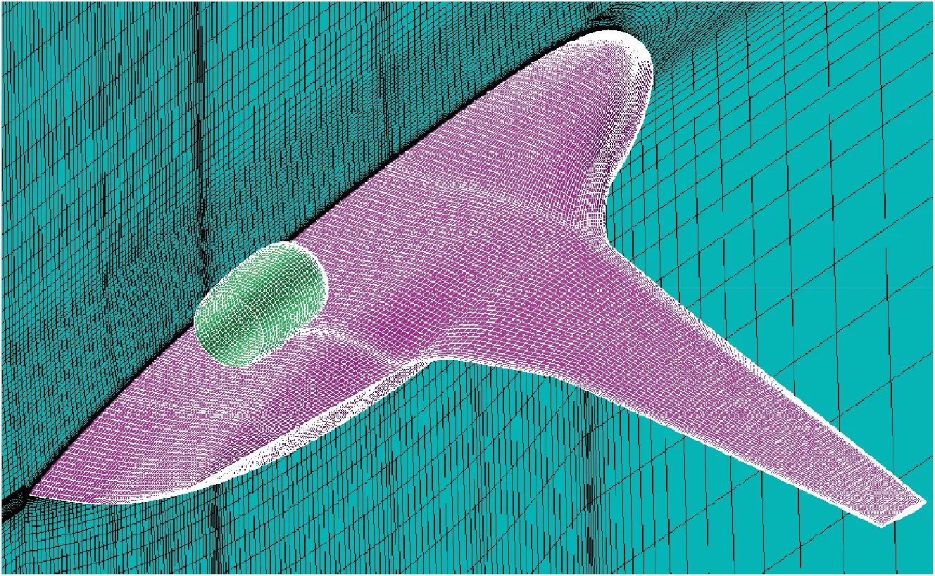
Fig. 2 Grids of research model.
The numerical method is validated by DLR-F6 Wing/Body/Pylon/Nacelle (WBPN) configuration20,21which is a transport aircraft designed for transonic flights and selected by the DPW-II committee.For this commonly used configuration, grids are produced with the same processing method as described in Section 2.1.The calculation state is as follows:free stream Mach number Ma∞=0.75, Reynolds number Re∞=3×10⁶,and angle of attack α=0.5°.The comparison of separation regions between the wind tunnel test and CFD results is shown in Fig.3 and the surface pressure distributions are depicted in Fig.4(Cpis the pressure coefficient,y/b and x/c are the nondimensional semispan station and nondimensional chordwise position respectively).
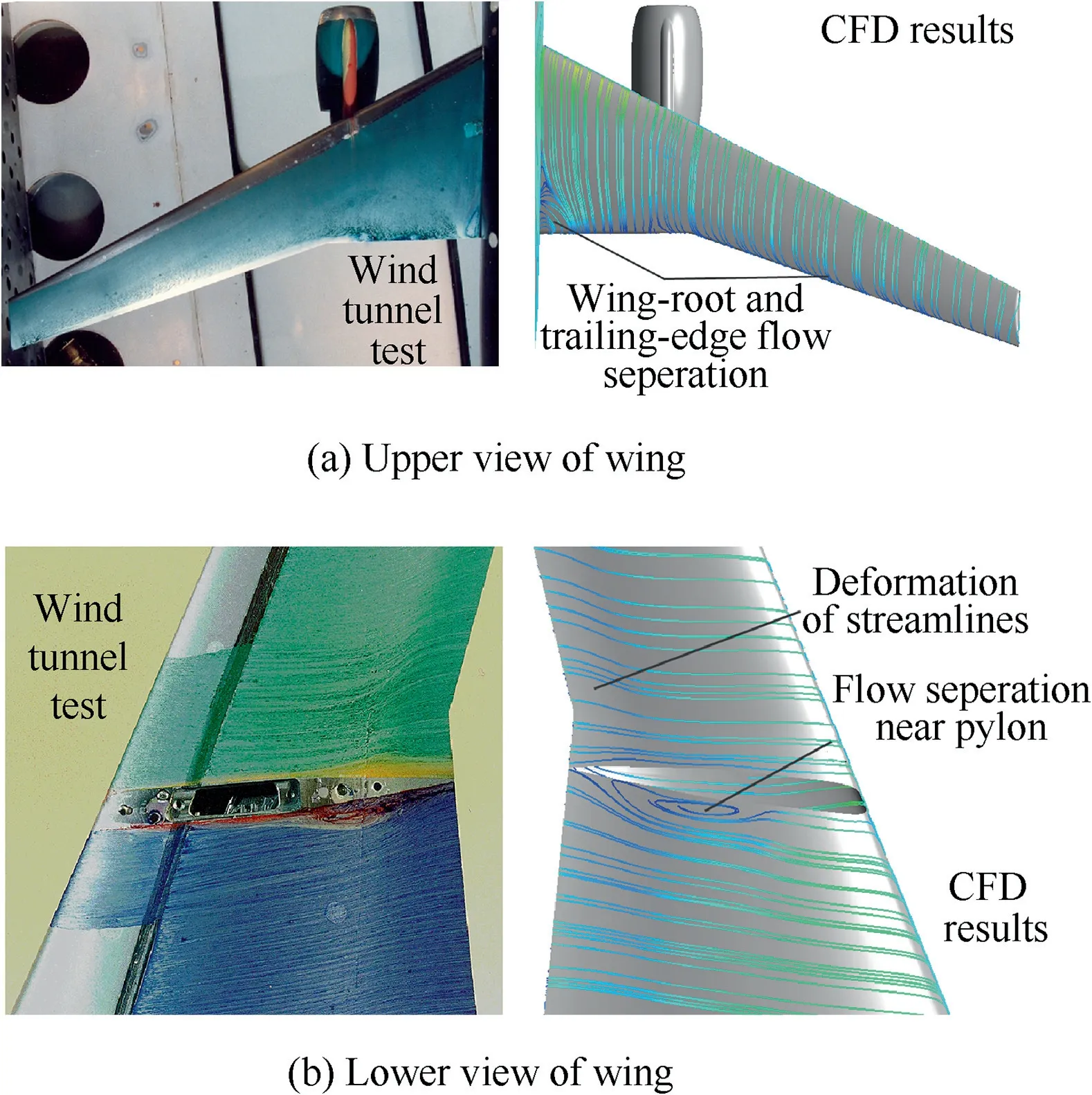
Fig. 3 Comparison of separation regions between wind tunnel test and CFD results.
It can be seen from Fig. 4 that the numerical simulations can effectively obtain flow separation at the wing root and pylon side though the separation regions are over predicted.The surface pressure distributions of CFD also fit well with the wind tunnel test data; therefore, the numerical simulation method adopted in this paper can precisely capture flow details, such as the location and intensity of shock waves, to meet the requirements for the research work.
3. Mechanism of flow interference between nacelle and airframe
Numerical simulations of the initial configuration are performed using the CFD method described in the previous section to illustrate the mechanism of flow interference between the nacelle and airframe. The simulations are based on cruise conditions in which Ma∞=0.85, Re∞(based on the mean aerodynamic chord of full projection area)=122.0×10⁶,and lift coefficient CL=0.2. The flow field information is shown in Fig. 5.
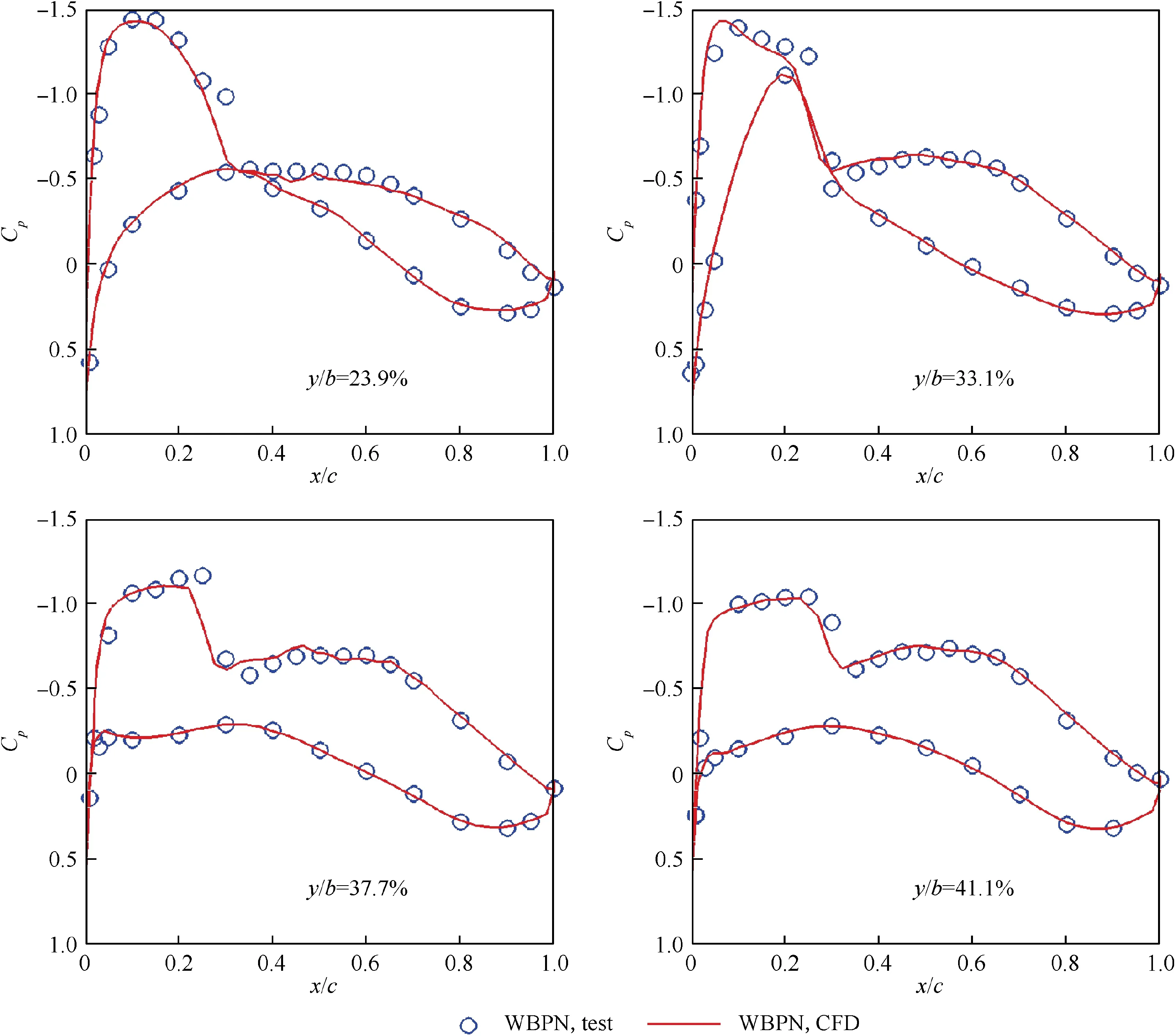
Fig. 4 Comparison of surface pressure distributions.
Fig. 5(a) shows a convergent-divergent channel below the nacelle with a strong throat effect.When flowing into the channel, air will accelerate rapidly to sonic speed near the minimal cross sectional area. A wide range of low pressure regions are formed on the nacelle and body surface. The inner region between the two adjacent nacelles reveals a weaker convergentdivergent characteristic. Because of the narrow space, the resulting low pressure extends to the rear part of the nacelle while the region of the outer space mainly concentrates near the lip (Fig. 5(b)). Behind the throat, the channel diverges due to contractions of the nacelle and body; hence, the flow further accelerates with a maximum speed (Mamax) reaching 1.43. The acceleration produces a large supersonic region around the nacelle and is finally terminated with a strong shock wave (Fig. 5(c)). As a result, flow separation is introduced with an adverse impact on the aerodynamic performance (Fig. 5(d)).
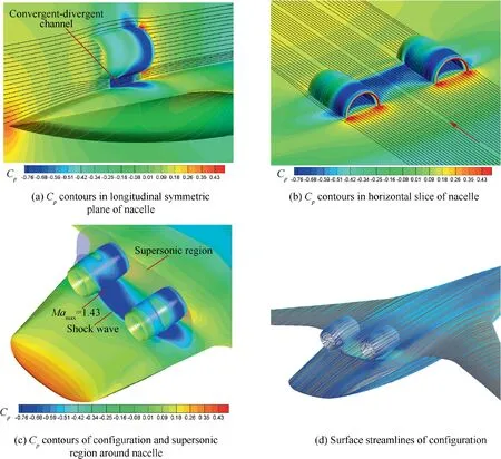
Fig. 5 Flow field information of initial configuration.
The above flow phenomenon indicates that the root cause of strong shock waves and flow separation is the convergentdivergent channel formed between a nacelle and body. Thus,the design philosophy of nacelle-airframe integration for podded BWB should channel the nacelle-airframe flow with the local throat effect avoided.
4. Design method for nacelle-airframe integration
4.1. Integration design method
According to the design philosophy proposed in Section 3,it is necessary to maintain the area distribution between the nacelle and body along the flow direction. Theoretically, this can be achieved by reshaping the airframe and nacelle contours or moving the engine positions if necessary. However, it is difficult for the latter two techniques to alter the channel shape,given that the nacelle outer cowl lines are often convex. Thus,this paper focuses on the body surface contouring with a fixed nacelle position.
Although the channel between the nacelle and body is three dimensional, the most fundamental reason for flow interference is the throat effect in the longitudinal symmetric plane of the nacelle.Therefore,the body surface contouring can start from the two-dimensional plane and then extend to threedimensional space.
The integration design mainly involves the longitudinal and spanwise part,as shown in Fig.6.Based on this design,a new fuselage is generated.
The longitudinal integration design of the symmetric plane of the nacelle is the basis of three-dimensional work. The aim of this design is to build the two-dimensional‘‘parallel”feature between the nacelle and body by constructing a new body contour curve S0.As shown in Fig.6(a),S0consists of three components: the ‘‘parallel” curve S’ and the B-spline transition curves on both sides. S’ is translated from the selected nacelle contour curve S. The combination among different curves should guarantee curvature continuity.
The spanwise integration design keeps the two-dimensional‘‘parallel” feature preserved in three-dimensional space with the following steps: First, after the selection of the spanwise planes in the front, rear and maximum depth position of S’(Fig. 6(a)), a circle with its center located on the centerline of the nacelle can be drawn in each plane. The radius of each circle is the distance between the center and intersection point with S’. All the spanwise planes are perpendicular to the centerline of the nacelle. On the basis of the circular curve AB which is intercepted by the initial airframe, a new spanwise body contour curve P1P3P4P2is constructed, as shown in Fig. 6(b). P1P3and P4P2are the transition curves between AB and the initial body contour for curvature continuity,respectively. Additionally, P1and P2are projected from the sides of the drawn circular; P3and P4are the middle points of AC and BC, respectively. The three new spanwise contour curves are named as S1, S2and S3, respectively.
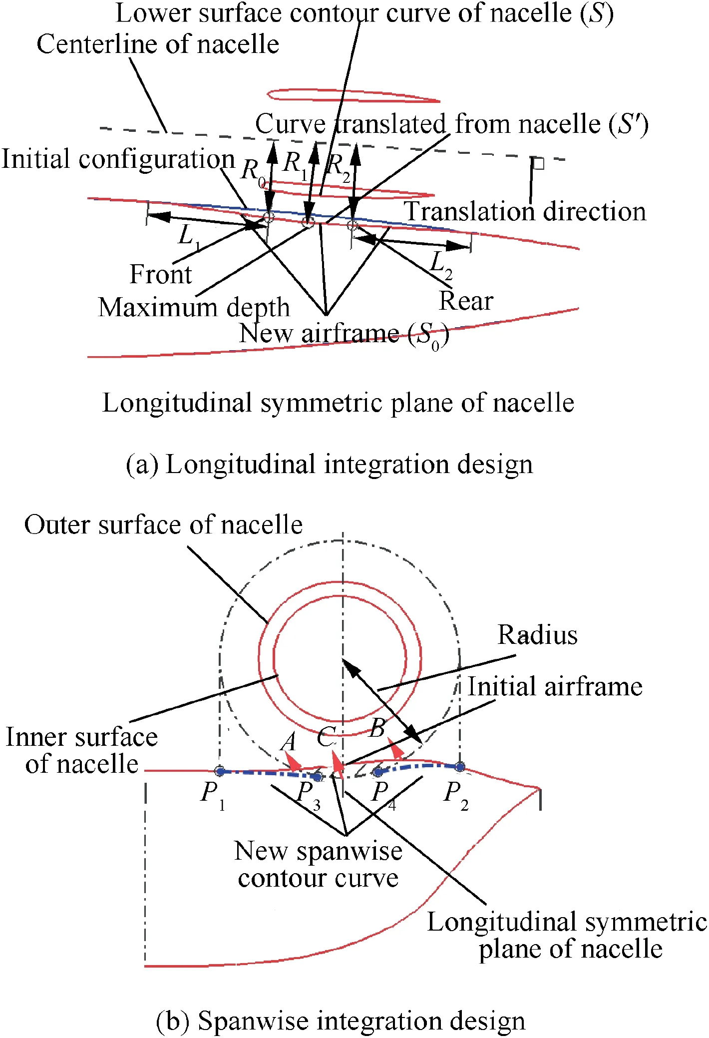
Fig. 6 Sketches of longitudinal and spanwise integration.
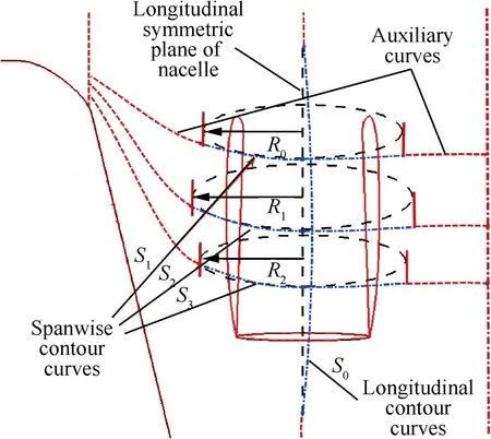
Fig. 7 Sketch of constructing a new fuselage.
After the longitudinal and spanwise integration designs,the last step is to produce a new fuselage with a profile under the nacelle changed as expected. This new spatial loft surface is constructed by combining the contour curves (S0, S1, S2, and S3) with the auxiliary curves extracted from the initial configuration, as shown in Fig. 7. The profile under the nacelle is determined by the blue contour curves, while the shape of other regions preserves a characteristic of the initial configuration by the red auxiliary dashed curves.
Table 2 shows all the control parameters of the integration design.It should be pointed out that R1is a special parameter which not only denotes the position of S0in the longitudinal design but also represents the radius of the circle in the maximum depth position of S’ during the spanwise integration.Considering that R0and R2are determined by the parameter R1when the position of S’ is fixed, it is reasonable to take R1, L1and L2as the key parameters for a further study.
4.2. Influence of key parameters
In Section 4.1, an integration design method based on the key parameters(R1,L1and L2)is proposed.In order to determine the selection principles of these parameters, further studies on their influences are carried out. Table 3 presents the typical configurations.
The depth and length of the forward and backward transition zones have been adjusted sequentially from Config.1 to Config.4 so that studies of individual parameters can be performed. The simulations are based on cruise conditions. The Mach number (Ma) contours in the longitudinal symmetric plane of the nacelle(Fig.8)show the performance of different configurations.
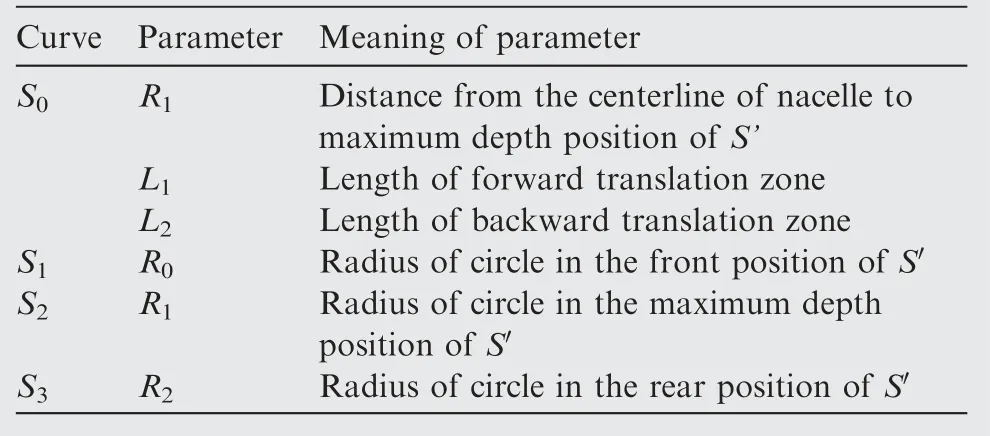
Table 2 Definition of control parameters.

Table 3 Typical configurations.
For the initial configuration,there is a high speed region in the throat position below the nacelle,with the maximum Mach number reaching 1.4. However, the four configurations designed possess completely different characteristics, which results from both the eliminated throat effect and local decelerated inflow as the supersonic region is reduced on the upper surface of the nacelle. In the channel below the nacelle, the supersonic flow mainly concentrates in the front and rear parts with a reduced Mach number. The front supersonic region is mainly caused by the rapid acceleration of the flow near the nacelle lip while the second one is due to the curvature variant on the nacelle surface and the slightly divergent channel shape.On the whole,the flow speed in the channel is around Ma=1 and no strong shock waves appear. Further, the influence of each parameter is studied based on relevant pressure distributions. Fig. 9 shows the body pressure coefficient distribution for different configurations at a position of y=4 m, where the longitudinal symmetric plane of the nacelle is located.
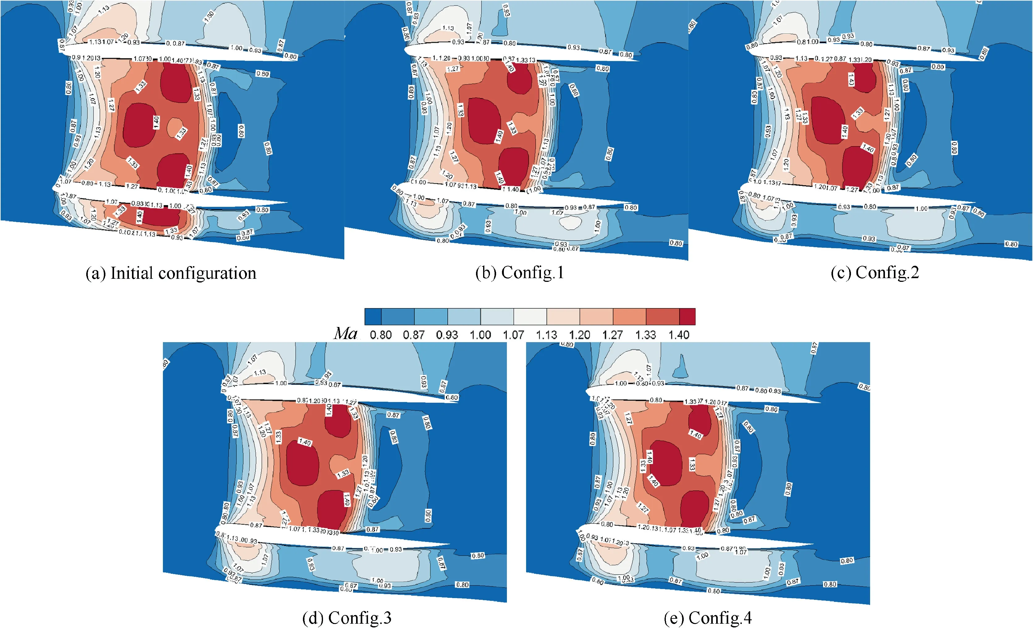
Fig. 8 Comparison of Mach contours in longitudinal symmetric plane of nacelle.
4.2.1. Influence of R1
This study examines the influence of the parameter R1by comparing the body pressure coefficient distributions between Config.1 and Config.2 (Fig. 9(a)). As R1increases, pressure distribution mainly changes in the chord range from 57% to 85%,which is also the region between the beginning of the forward transition zone and the end of the backward transition zone (Fig. 9(a)). At the 57% chord position, there appears an abrupt ‘‘Bump” mainly because of the relatively large curvature of the modified body surface.If the depth increases,the‘‘Bump” becomes more serious. Afterwards, two pressure peaks of each configuration caused by the supersonic regions below the nacelle can be clearly seen.The peak values of Config.1 exactly reach Cp*, which means that the local flow speed is sonic and that the instability of the boundary layer is introduced. However, the corresponding values of Config.2 are effectively reduced, benefiting from a larger R1. In the chord range from 80% to 85%, Config.2 possesses higher Cpas the increasing R1brings a larger curvature of the body surface and speeds up the flow there, which is a situation similar to the forward increased ‘‘Bump”.

Fig. 9 Comparison of body pressure coefficient distributions for different configurations.
As shown in the Mach number contours of the two configurations (Fig. 8), the supersonic regions below the nacelle of Config.2 shrink significantly. The local flow tube expands; as the body contour changes with a more concave shape, the inflow decelerates. This can be judged from the slightly reduced supersonic region on the nacelle upper surface. Thus,the reduction of the Cppeak values of Config.2 is caused not only by a larger distance between the body and nacelle surface,but also by the completely reduced flow speed.
According to the above results, it can be summarized that the increase of R1can effectively slow down the flow below the nacelle, resulting in a lower pressure peak. However, the‘‘Bump” condition becomes worse because of the enlarged local surface curvature.
4.2.2. Influence of L1
By comparing the distributions of the surface pressure coefficient between Config.2 and Config.3 (Fig. 9(b)), this study examines the influence of the parameter L1. Compared with Config.2, Config.3 has a larger forward transition zone where the surface changes more smoothly. The variation of pressure coefficient distribution concentrates in the chord range from 50% to 70%, as shown in Fig. 9(b). For Config.3, the beginning of the forward transition zone moves to the 50% chord position where the increased curvature causes local flow to accelerate and forms a higher negative pressure peak. However, as the surface changes more gently along the larger forward transition zone, the pressure distribution is smoothed.In addition, in the chord range from 65% to 80%, the first pressure peak under the nacelle increases significantly whereas the second one is almost unchanged.
A comparison of the Mach number contours of the two configurations (Fig. 8) shows that extension of the forward transition zone expands the supersonic regions under the nacelle, especially the region nearby the lip. This is mainly due to the accelerated inflow as the body concave shape is somewhat smoothed. The first supersonic region experiences a rapid acceleration, quite sensitive to the variation of the inflow speed. The overall velocity distribution of the second supersonic region is more uniform, and the pressure distribution does not change obviously.
According to the above results,the increase of L1smoothes the body surface in the forward transition zone,but speeds up the flow under the nacelle.
4.2.3. Influence of L2
This study investigates the influence of the increasing L2by comparing the body pressure coefficient distributions between Config.3 and Config.4(Fig.9(c)).With expansion of the supersonic regions under the nacelle, the results are basically the same as those of L1. The mechanisms are not repeated here for the sake of space.
4.3. Principle of key parameters selection
The analysis from Section 4.1 to Section 4.2 shows that the increase of the depth parameter R1can effectively reduce the range of supersonic regions below the nacelle. However, to ensure a smooth body surface, a larger range of forward and backward transition zones may be required, which will cause an adverse impact. The inflow condition below the nacelle influenced by body contouring plays an important role; therefore, the key parameters need to be carefully selected to make the overall flow characteristics acceptable.Generally,the selection of these key parameters is directly related with many influencing factors, like: the design point of cruise, the contouring and position of relative components. The weaken shock wave design near the lip of nacelle and the lower cruise speed are beneficial to the flow condition between the nacelle and body.Thus, it is hard to give out the value of the parameters quantitatively.Based on the results of study in this paper and taking into account the significant difference between various BWB configurations, the selection principle of the key parameters is formulated qualitatively. The negative pressure peaks of the body under the nacelle should not reach the critical pressure Cp* to minimize the nacelle and airframe interference and to prevent the possibility of shock induced separation.The body surface should be smooth enough to avoid the appearance of an abrupt ‘‘Bump” in the Cpdistribution.
5. Integration design and analysis

Table 4 Comparison of aerodynamic performance between different configurations.

Table 5 Comparison of drag between different components.
According to the principle put forward in Section 4, the integration design is completed with a further modification to Config.4.R1is finally slightly increased.The aerodynamic performance of the designed configuration,compared with that of the initial one, is presented in Tables 4 and 5. CDis the drag coefficient, CDfis the friction drag coefficient and CDpis the pressure drag coefficient. The simulation conditions are set with the cruise lift coefficient at the value of 0.2. Actually,there is a little decrement of angle of attack for the designed configuration (Initial: 1.7°, Designed: 1.5°). If both configurations are set with the same angle of attack (1.5°), the lift coefficient of the initial one is 0.187,a little smaller than that of the designed one.The pitching moment coefficient is also changed(Initial: 0.0026, Designed: 0.0015).
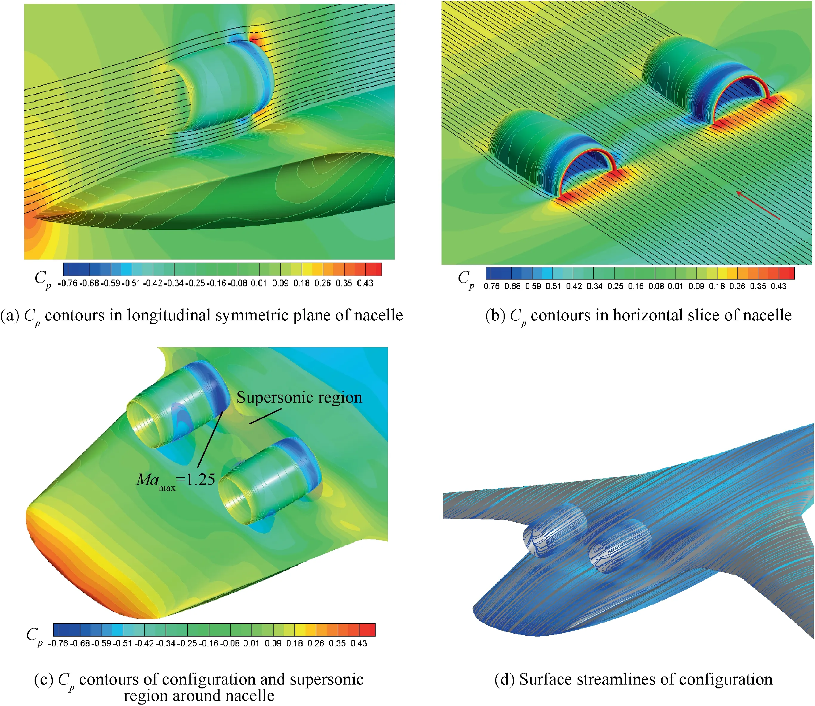
Fig. 10 Flow field information of designed configuration.
Compared with the initial configuration, the drag coefficient at cruise condition can be reduced by 8.7% through the integration design. Note that the reduction of the total drag completely benefits from the improved performance of the pressure drag. The friction drag is almost unchanged. From Table 5, by decomposing the friction and pressure drag into two parts which are contributed by body and nacelle respectively, it can be found that both changes of the friction drag are not obvious. But, the body pressure drag is significantly reduced by 18.9%. The relative large pressure drag of the nacelle is mainly due to the strong shock wave on the inside surface (Fig. 8) and gets even worse after the integration design.
Fig. 10 depicts the flow field information of the designed configuration. The supersonic regions around the nacelle of this configuration, compared with those of the initial one, is significantly reduced with the maximum Ma changed from 1.43 to 1.25 and located in the front due to the elimination of the throat effect. In addition, the strong shock wave and flow separation disappear, which remarkably decreases the pressure drag of the body and improves the aerodynamic performance. However, the low pressure region on the outer surface of the nacelle is mainly distributed near the lip. This change reduces the forward force component induced by the suction peak which is responsible for the worse pressure drag of the nacelle.
6. Conclusions
(1) It is easy for the convergent-divergent channel between the nacelle and body to produce strong shock waves and flow separation, thus exerting adverse impact on the aerodynamic performance of the BWB configuration with podded engines. This problem can be effectively solved by the nacelle-body integration design with the philosophy of reasonably channeling the flow and avoiding the throat effect.
(2) The integration design method proposed in this paper mainly involves longitudinal and spanwise parts, generating a new body eventually. This method is carried out from two-dimension to three-dimension space, maintaining the ‘‘parallel” feature of the two-dimensional longitudinal design in three-dimensional space by further spanwise design.
(3) Through the integration design,the original large supersonic region below the nacelle is replaced by two minor ones. One minor region is caused by the flow acceleration near the nacelle lip while the other results from the curvature variant on the nacelle surface and from the slightly divergent channel at the rear. In general,the improvement is a result not only of the reshaped channel, but also of the decelerated inflow below the nacelle as the body contouring introduces a negative camber.
(4) The increasing depth parameter R1can effectively reduce the range of supersonic regions, while expanding the area of forward and backward transition zones plays an opposite role.A key factor involved is the inflow condition below the nacelle influenced by the body contouring. Considering there are various influencing factors,the selection principles of the key parameters are qualitatively proposed.Both limited pressure peaks under the nacelle and smooth body surface are guaranteed to prevent the possibility of shock induced flow separation and abrupt ‘‘Bump” in the pressure coefficient distribution.
(5) For the configuration reported in this paper, the drag coefficient in the cruise condition can be reduced by 8.7% through the integration design. Improvement of the drag performance is completely due to the decrease of body pressure drag after elimination of the strong shock wave and flow separation; however, the pressure drag of the nacelle becomes worse mainly because of the greatly reduced low pressure region on the outer surface.
Acknowledgements
This work was supported by the Fundamental Research Funds for the Central Universities (Nos. 3102019JC009 and G2016KY0002).
 CHINESE JOURNAL OF AERONAUTICS2019年8期
- CHINESE JOURNAL OF AERONAUTICS的其它文章
- Special Column of BWB Civil Aircraft Technology
- Assessment on critical technologies for conceptual design of blended-wing-body civil aircraft
- Exploration and implementation of commonality valuation method in commercial aircraft family design
- Effects of stability margin and thrust specific fuel consumption constrains on multi-disciplinary optimization for blended-wing-body design
- On developing data-driven turbulence model for DG solution of RANS
- Numerical investigation on flow and heat transfer characteristics of supercritical RP-3 in inclined pipe
