
Numerical Simulation of a New 3D Isolation System Designed for a Facility with Large Aspect Ratio
2019-09-21 08:43:46YingZhouandPengChen
YingZhouandPengChen
Abstract: This paper proposes a novel three-dimensional (3D) isolation system for facilities and presents the numerical simulation approach for the isolated system under earthquake excitations and impact effect using the OpenSees (Open System for Earthquake Engineering Simulation) software frame work.The 3D isolators combine the quasi-zero stiffness (QZS) system in the vertical direction and lead rubber bearing in the horizontal direction.Considering the large aspect ratio of the isolated facility,linear viscous dampers are designed in the vertical direction to diminish the overturning effect.The vertical QZS isolation system is characterized by a cubic force-displacement relation,thus,no elements or materials can model this mechanic behavior in the existing finite element software.This study takes advantage of the open source feature of the OpenSees to create a new material to represent the mechanic properties of the QZS system.Then the user-defined material is combined with the rubber isolator element to model the 3D isolator.Considering different soil types and input magnitudes,six sets of natural seismic records and artificial waves and half sine pulses are selected as the input excitations.A finite element model for the 3D isolated facility is established based on the combined element and the simulation is performed to calculate the time history response.The numerical simulation reveals the flexibility of the OpenSees to deal with new engineering problems,and the results prove that the new 3D isolation system can have an optimal isolation effect in both horizontal and vertical directions.The maximum acceleration response at the top of the facility is below the target limit,and the maximum deformation and the overturning motion of the isolation system can be controlled in a safe range.
Keywords: 3D isolation,quasi-zero stiffness,OpenSees,facility,large aspect ratio.* Corresponding Author:Ying Zhou.Email:yingzhou@tongji.edu.cn.
1 Introduction
Base isolation technology is one of the most popular passive control strategies for seismic protection of buildings or facilities,and it is referred to as the most significant invention in the field of earthquake engineering in recent decades.Significant seismic reduction effect of this technology has attracted an enormous amount of research and many isolated buildings have been built in China,Japan,US,New Zealand,etc.[Asher,Young and Ewing (1996);Zayas,Low,Bozzo et al.(1989);Zhou and Chen (2017)].Base isolation technology has also been applied to the seismic protection of critical equipment or lifeline facilities [Tsai and Kelly (1989);Shinozuka,Feng,Dong et al.(2003)].However,most of the existing isolation systems can only isolate the seismic action in the horizontal direction,seldom of them can have a satisfactory isolation effect in the vertical direction.
In the early development of the seismic isolation system,researchers and engineers had paid efforts on combining the horizontal seismic isolation with vertical vibration isolation.This is mainly driven by the power and utility industries focused on the protection of large equipment [Warn and Ryan (2012)].In addition to the seismic threat,environment vibration such as impact effect would also influence the regular operation of high precision facilities.
Many research interests on three-dimensional (3D) isolation system lie on the thick-layer laminated rubber bearings.The bearing shape factor which determines the vertical stiffness of the bearing can be adjusted by changing the thickness of the individual rubber layers [Warn,Whittaker and Constantinou (2007)].Thus,the key to the vertical isolation approach is to decrease the vertical stiffness of the isolation system.A 2-story reinforced concrete acoustic laboratory in Japan is designed using thick layer rubber bearings.The bearings are more vertically flexible and can provide a vertical natural frequency of 5 Hz,according to Kelly [Kelly (1988)].Pan et al.[Pan,Shen,Shen et al.(2018)] conducted high-frequency dynamic tests on small scaled thick layer rubber bearing to reveal the vertical isolation effect for metro induced vibration and then put into use on an isolated residential building above metro.The use of the laminated rubber bearing for 3D isolation was also explored for the unclear industry by Kelly [Kelly (1989)].Despite multiple research and engineering practices,the application of 3D isolation to the elastomeric bearing is limited due to the stability issues,see Buckle et al.[Buckle,Nagarajaiah and Ferrell (2002);Buckle and Liu (1994)].As the thickness of rubber layers increases,the vertical stiffness can be reduced but the critical load capacity of the bearing decreases proportionally.Zhou et al.[Zhou,Chen,Lu et al.(2016)] studied the engineering isolation design using thick layer bearings,and prove that the 3D isolation design would lead to a less effective horizontal isolation effect.
Japanese researchers and engineers actively investigated the 3D isolation system using air spring or pressurized air in the vertical direction,for example,Kashiwazaki et al.[Kashiwazaki,Shimada,Fujikawa et al.(2003);Inoue,Morishita and Fujita (2004);Suhara,Matsumoto,Oguri et al.(2005)].The proposed system can have vertical isolation periods on the order of 1-2 seconds,and it is supposed to have a significant seismic isolation effect.However,for this type of device,the construction is complex and the overturning effect is significant [Kageyama,Hino and Moro (2004)].GERB Company proposed using helical spring and viscous dampers for 3D earthquake protection of building or vibration isolation of diesel and turbo generators [Hüffmann (1985)].A residential building isolated with the GERB system in California was shaken strongly in the 1994 Northridge earthquake.It is reported that the observed vertical ground motion was not significant,but the horizontal isolation was less effective than a typical isolation system [Hakris and Deoskar (1996)].
For 3D isolation system,how to implement the vertical isolation is the key problem.Generally,the basic idea of isolation impedes the use of vertical isolation system due to (1) large initial settlement by the gravity and the large isolation drift,and (2) rocking stability of the isolation system caused by overturning effect [Liu,Jing,Daley et al.(2015)].Recently,the development of negative stiffness device provides new ideas for vertical isolation.Cimellaro et al.[Cimellaro,Domaneschi and Warn (2018)] numerically investigated using vertical supplementary pre-stressed helical spring based negative stiffness devices in 3D isolation system.Rivin et al.[Rivin (2003);Carrella (2008);Meng,Sun and Wu (2015)] proposed using quasi-zero stiffness (QZS) isolation system based on disc spring and helical spring in vertical direction.It is concluded that the vertical isolation effect can be optimized by adding negative stiffness devices.
This paper presents a new 3D isolation system to isolate a facility with an overly large aspect ratio which utilizes QZS system in the vertical direction and lead laminated rubber bearing in the horizontal direction.Linear viscous dampers are used to restrain overturning motion.The concept of isolation and design approach of the 3D isolation system is presented firstly,then a series of seismic numerical comparison simulation is conducted using OpenSees software to verify the isolation response of this system.Contributions of this study are:(1) Propose a novel 3D isolation solution using stiffness nonlinear devices in the vertical isolation for large facilities or buildings.(2) Implement an applicable seismic and impact simulation approach in OpenSees and numerically prove the isolation effectiveness of the new system in horizontal and vertical directions.
2 Design concept of the 3D isolation system
2.1 General description and requirement of the isolated facility
The facility has a cylinder shape with a radius of 2.0 m and a height of 18.0 m.The designed mass is 60 ton,and the center of the mass is about 8.0 meters high.The fortification intensity of the facility location is 8 according to the Chinese seismic design code [GB 50011 (2010)].The peak acceleration of the maximum considered earthquake is 0.4 g.For the seismic control demand of the isolated facility,it is required that the maximum acceleration response is controlled under 0.5 g in both horizontal and vertical directions under maximum earthquake input.Besides,the isolation system should have the ability to reduce impact effect and the size of the isolation platform cannot be too large.
2.2 Concept of the 3D isolator
On the consideration of the vertical isolation demand,for the isolation design,the vertical quasi-zero isolation system is introduced combined with horizontal isolation system.The schematic diagram of the proposed 3D isolator is presented in Fig.1.The new 3D isolator comprises of the upper connection plate,QZS isolation system (including the helical spring,disc spring,and the loading rings),middle connection plate,laminated lead rubber bearing,and the under connection plate.Gravitational force would firstly transmit to the QZS system (the disc spring and helical spring would sustain the force in parallel) and then to the laminated rubber bearing.The upper and middle connection plates are occlusive together to decouple the horizontal and vertical deformation of the isolator.By the decouple design,the laminated rubber bearing and QZS system can isolate horizontal and vertical excitations separately.The 3D illustration of the QZS system is given in Fig.2.
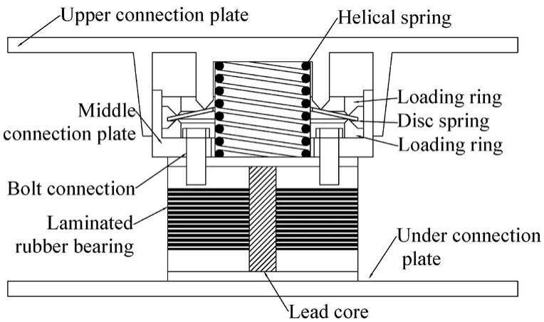
Figure 1:Schematic diagram of 3D isolator
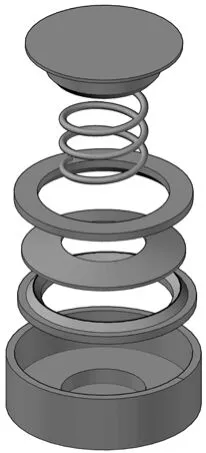
Figure 2:3D model of the QZS system
2.3 Design scheme of the 3D isolation system
The facility with 3D base isolation system is presented in Fig.3.A number of four 3D isolators mentioned before are designed symmetrically under the isolation platform to support the facility.Due to the motion decoupling construction of the proposed 3D isolator between the horizontal and vertical direction,the laminated bearing design can be performed in a traditional process which is documented in ASCE 7-10 [ASCE 7-10 (2010)].The design parameters of the laminated bearing are shown in Tab.1 and the design procedure of the QZS system is shown in the next section.To restrain the overturning motion of the upper facility,four viscous dampers are designed with each viscous damping coefficient is 3.5×10⁷ N*s/m.The under columns are used to adjust the height of the isolators and the dampers.
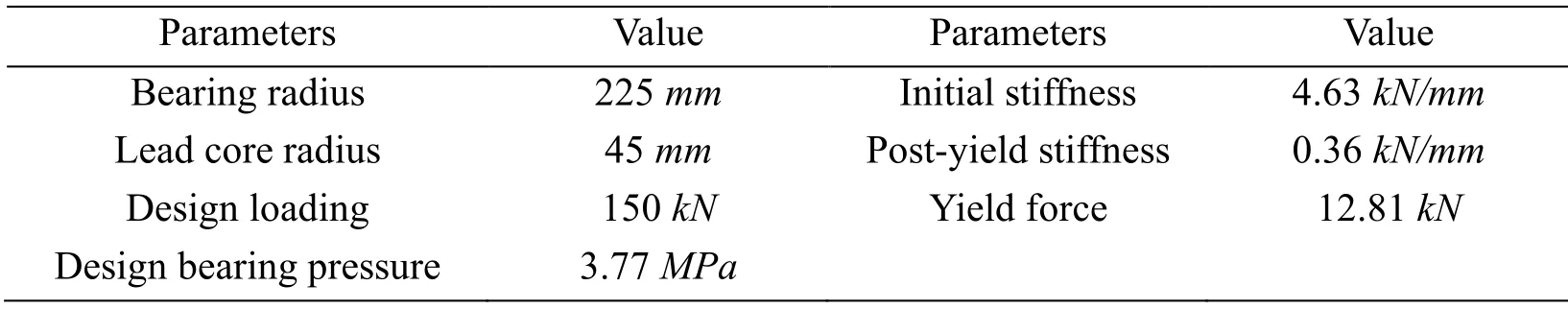
Table 1:Design parameters of laminated rubber bearing
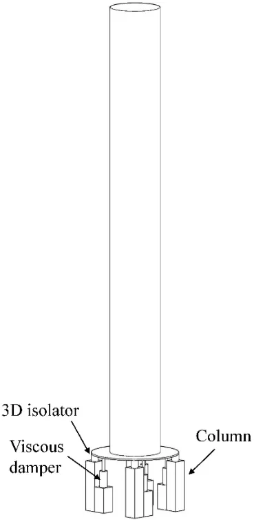
Figure 3:Schematic diagram of 3D isolator
3 Design approach of the QZS isolation system
The geometric dimensions and loading position of a disc spring is given in Fig.4(a).The restoring force-displacement relation of the disc spring has been given in Meng et al.[Meng,Sun and Wu (2015);Rivin (2003)] as follow,
where x is the vertical displacement of the QZS system,Fdis the corresponding restoring force.r1andr2are the external and internal radius,d1andd2are the distance between the central axis and the lower and upper loading positions,h is the height of the inner cone,t is the thickness of the disc spring.E andµrepresent the elastic modulus and the Poisson ratio of the material.
To further simplify the Eq.(1),the inner cone height,loading distance ratioCand two calculation parametersMandNare defined as,
After transforming the coordinate usingu=x-h,and combining the disc spring and helical spring shown in Fig.4(b),the total restoring force of the QZS system is

where k is the stiffness of the helical spring.The stiffness of the system is given as

By calculating the stiffness and loading capacity at the flat position (u=0),the designed loading capacity and designed minimum stiffness (to avoid the negative stiffness in the system) are


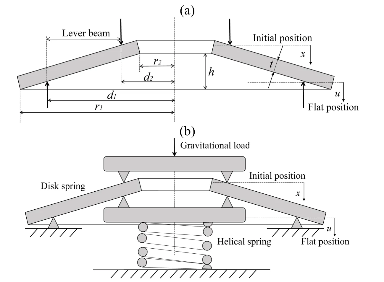
Figure 4:The schematic diagram of (a) disc spring and (b) quasi-zero stiffness vertical isolation system
Eq.(8) and Eq.(9) are used for designing an appropriate loading capacity and the vertical stiffness of the 3D isolation system,and the design parameters of the QZS system are listed in Tab.2.For the vertical QZS isolation system,the disc spring is designed first.The disc spring is considered to undertake the main part of the gravitational force and provide the negative stiffness at its flat loading situation.Then,the helical spring is designed based on the negative stiffness of the disc spring,to ensure the isolation system is at the quasi-zero situation loaded with upper facilities.The restoring force and stiffness curves of the designed QZS system are presented in Fig.5.The stiffness of the vertical QZS system can be designed at a small value,while it can also provide a large loading capacity with comparatively small static displacement.
Table 2:Design parameters of vertical QZS isolation system
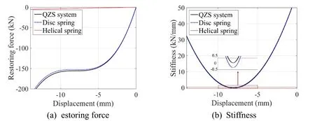
Figure 5:The designed static mechanic property of the vertical QZS isolation system
4 Simulation on the isolation system
4.1 Selection of input earthquake records
Three different soil types (type I0,II and III) and two input magnitudes (minor and major) are considered,thus 6 sets of earthquake records (5 natural and 2 artificial waves) are selected based on the design spectrum.The earthquake records are presented in Fig.6.The natural waves are downloaded from the PEER NGA database [Chiou,Darragh,Gregor et al.(2008)],and the detailed information is listed in Tab.3.
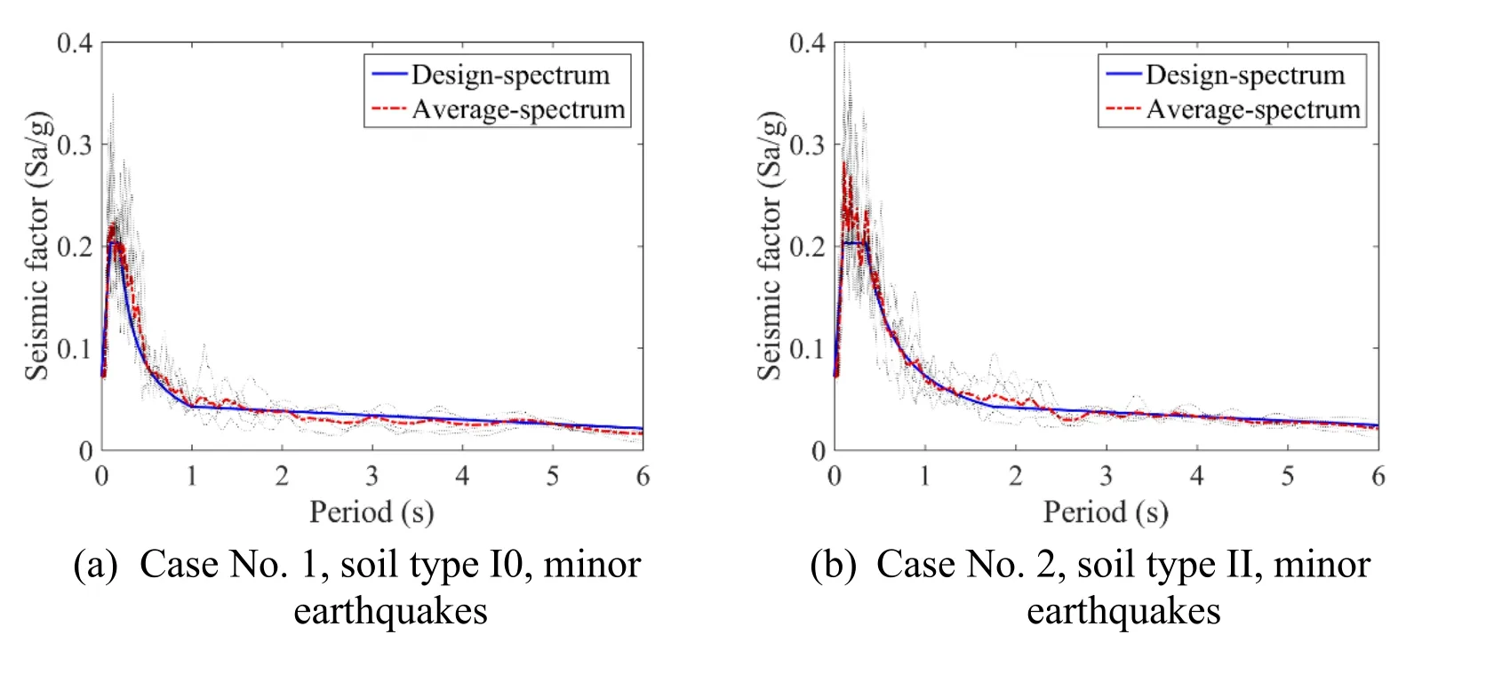
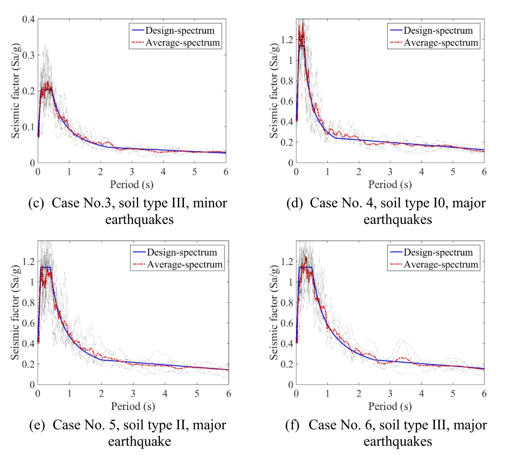
Figure 6:Spectrum comparison between earthquakes selected for analysis and the design spectrum
The seismic waves are considered in two horizontal and the vertical directions,and the ratio among the main horizontal,secondary horizontal and vertical acceleration peak value is 1.0:0.85:0.65.The maximum horizontal acceleration is 70 gal and 400 gal for minor and major earthquakes.The design spectrum and the minor and major earthquake levels which correspond to the design and maximum considered earthquakes are both defined in the Chinese code [GB 50011 (2010)].
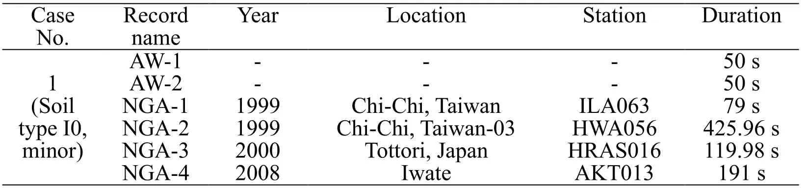
Table 3:Information of the input earthquakes
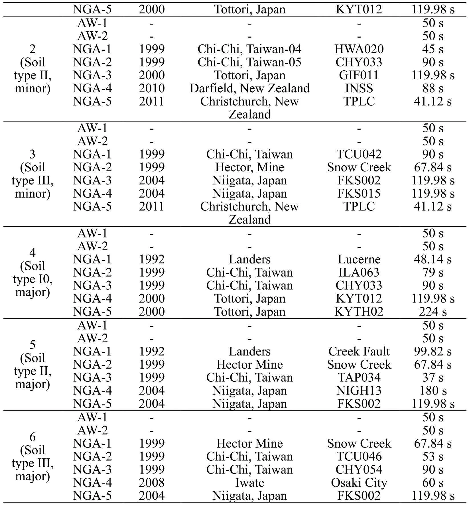
NGA-5 2000 Tottori,Japan KYT012 119.98 s AW-1 - - - 50 s AW-2 - - - 50 s 2 NGA-1 1999 Chi-Chi,Taiwan-04 HWA020 45 s ty(pSeo iIlI ,NNGGAA--23 12909090 ChiT-Cothtoi,r iT,aJiawpaann- 0 5 CGHIFY001313 11990.9 s8 s minor) NGA-4 2010 Darfield,New Zealand INSS 88 s NGA-5 2011 Christchurch,New TPLC 41.12 s Zealand AW-1 - - - 50 s AW-2 - - - 50 s (S3o il NNGGAA--12 11999999 ChHie-Ccthoir,,TMaiiwnea n SnToCwU C04re2e k 679.08 4s s type III,NGA-3 2004 Niigata,Japan FKS002 119.98 s minor) NGA-4 2004 Niigata,Japan FKS015 119.98 s NGA-5 2011 Christchurch,New TPLC 41.12 s Zealand tmy(pSa 4ejoo iIrl0 ),NNNN AAGGGG WWAAAA------121234 1112 9990--9990 2990 CCThhoii--t LCCt o ahhrniii--,,d,TT eJ a raaspii wwa n aa nn CK LI LHY uAcYT--e0 00r 6n133e23 1 418 55799.0090.19 4ssss8 s s NGA-5 2000 Tottori,Japan KYTH02 224 s tmy(pSa 5ejoo iIrlI ),NNNN AAGGGG WWAAAA------121234 1112 9990--9990 2994 CNhHii-i eLgCcaathotnia--r,d,T M eJraasiipn w aena n SCnNrToeAIewGkP-- H C0 F 3r1 ae43 ue l k t 96197 5538..007880 24sss s ss NGA-5 2004 Niigata,Japan FKS002 119.98 s AW-1 - - - 50 s ty m(pSae 6jo o IirlI )I ,NNNNN AGGGGG WAAAAA------212345 11122 99900-99900 9 9984 CCNhh Hiii--i egCCcIa thhwot iia-r,,a,TTt M Jeaaa iii p nwwa enaa nn SOnCTFsoCHKawkUYS- iC0 00 C 0 r45ei264tey k 1 61 755969.0300.89 4ssss8 s s
4.2 Finite element model for the isolation system
OpenSees software [McKenna,Fenves and Scott (2000)] developed by Pacific Earthquake Engineering Research (PEER) center is used to establish the finite element model.A new material is created in OpenSees using C++ coding language to simulate the mechanic behavior of the vertical QZS isolation system,and it is combined withelastomericBearingPlasticityelement to model the 3D isolator.The upper isolated facility is simplified using a stick model and the supplementary vertical viscous damper is modeled usingTwoNodeLinkelement with the viscous material.The diagram of the numerical model is shown in Fig.7.
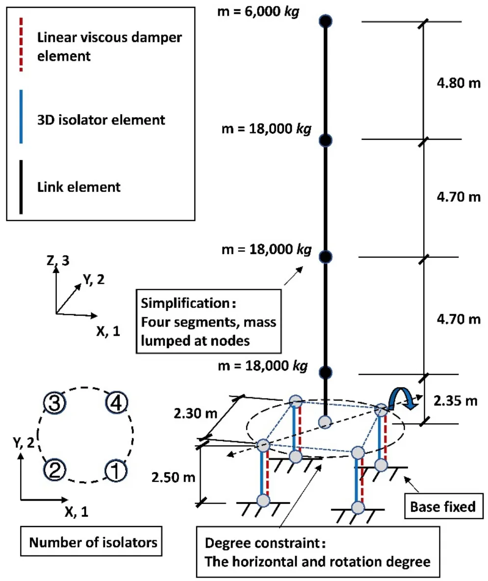
Figure 7:Simplified finite element model of the 3D isolated system
4.3 Seismic response of the 3D isolated system
To ensure the working stability of the horizontal elastomeric bearing,it is required that the maximum horizontal deformation cannot exceed the upper limit defined as the smaller value between 0.55Dand 300% γ (Dis the effective radius of the bearing and γ is the total thickness of rubber layers) [GB 50011 (2010)].For this isolation system,the horizontal limit is 99 mm (0.55D).For the vertical direction,the QZS system is not designed with tension-resistant ability,thus the tensile deformation of the isolator is not allowed.
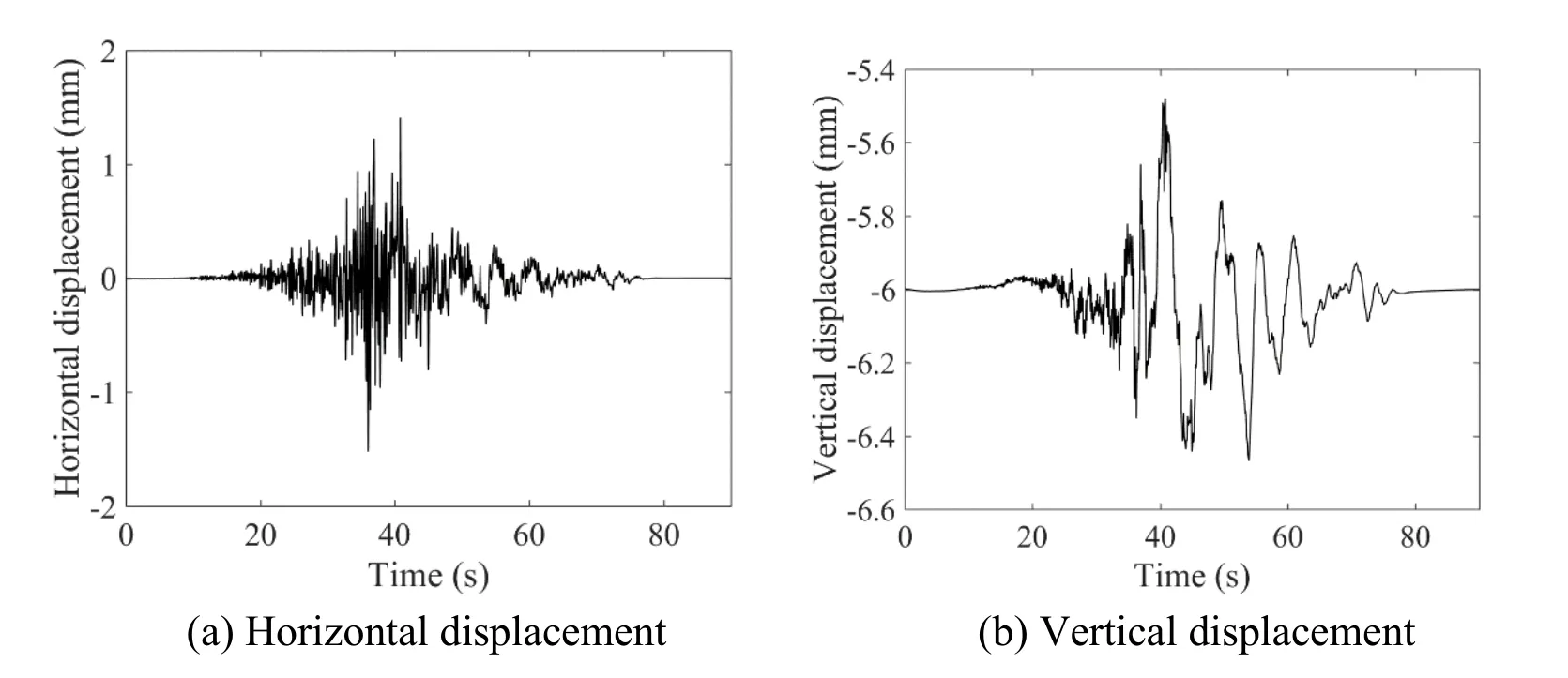
Figure 8:Time history isolation layer displacement response of the 3D isolated facility under case No.1,NGA-1 earthquake input (Soil type I0,minor input)
Figs.8 and 9 present the time history displacement response of the 3D isolation system under case No.1,NGA-1 minor and case No.4,NGA-1 major seismic input.For the vertical displacement,the gravity-induced static displacement is also considered as the initial displacement condition.To calculate the maximum rotational angle,it is assumed that the most significant rotational movement occurs around the diagonal axis at the isolation platform (shown in Fig.7).Under the minor input shown in Fig.8,the horizontal isolation system has barely been activated.However,the vertical system can work well both under minor and major inputs.The displacement response considering major seismic input is much larger than minor input,but the peak response can be controlled within the displacement limit.The vertical displacement time history result of an isolator with no additional dampers considered is presented in Fig.9(d).A large uplift response has been observed which is dangerous for the upper base-isolated structure.By adding the vertical viscous dampers,the tension displacement does not occur and the overturning motion is not significant (Figs.9(b) and 9(c)).
The restoring force dynamic response of the vertical QZS isolation system is presented in Fig.10.It is proved that the newly created material in OpenSees can accurately represent the displacement-dependent stiffness character of the QZS isolation system.
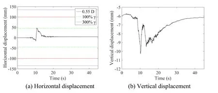
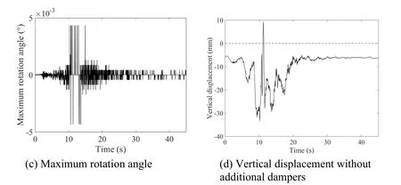
Figure 9:Time history isolation layer displacement response of the 3D isolated facility under case No.4,NGA-1 earthquake input (Soil type I0,major input)
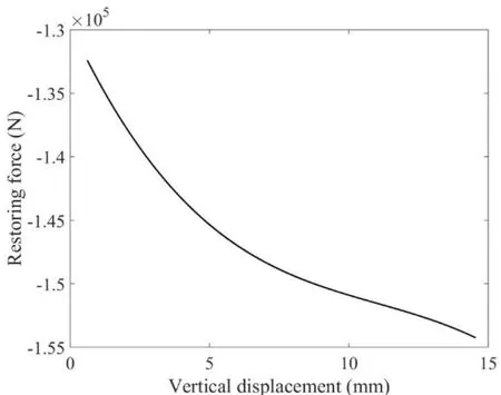
Figure 10:The restoring force of the QZS system under case No.4,NGA-1 earthquake input (Soil type I0,major input)
To properly evaluate the seismic response,for each analysis case,the average and variance values for the 7 waves of each case are presented in Fig.11.Based on the results calculated by multiple seismic inputs considering different earthquake magnitudes and soil types,it is concluded that the isolation design can meet the requirement of horizontal displacement limit.Besides,no uplift and overturning effect is observed by adding the vertical viscous dampers.Due to the three directional input,the maximum horizontal displacement and rotational motion occur at the corresponding diagonal direction shown in Fig.7.The numerical simulation also proves that the soil type with the longer natural period would result in significantly larger peak displacement response.
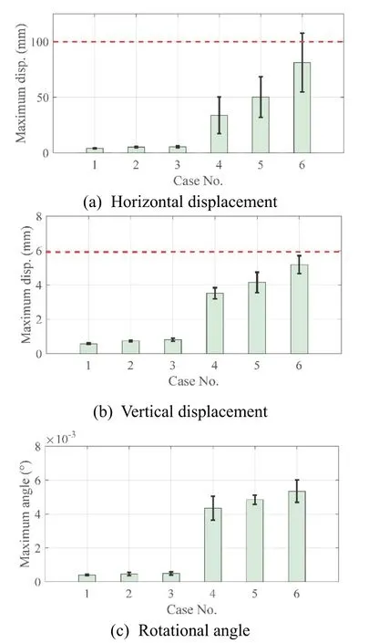
Figure 11:Maximum displacement response (average and variance value) of the 3D isolation system
The maximum acceleration response on the top of the isolated facility is used to evaluate the isolation effect of the isolation system.The design target is to control the peak acceleration under 0.5 g.The numerical simulation shows that the 3D isolation design can meet the predetermined design target,and the vertical isolation effect is superior to the horizontal direction.
Figs.12 and 13 present the time history acceleration response of the 3D isolated facility under case No.1,NGA-1 minor and case No.4,NGA-1 major seismic input.As it is shown in the figures,the acceleration response under major seismic input is significantly larger than the minor input.But considering the input magnitude,for the horizontal direction the isolation effect for higher input magnitude is significantly better.For the vertical direction,the isolation effect is not strongly related to the input magnitudes.The average and variance results for each input cases are given in Fig.14.The amplification factor (AF) is calculated using the ratio between the peak acceleration response and peak seismic input and it is also given in Fig.13.Maximum acceleration in both horizontal and vertical direction does not exceed the predetermined 0.5 g design limit.The acceleration response in the vertical direction is significantly smaller than in horizontal direction,one reason is that the magnitude of considered vertical input is smaller than horizontal input,and it is also proved that the vertical QZS isolation system has a better isolation effect than horizontal elastomeric isolation system.
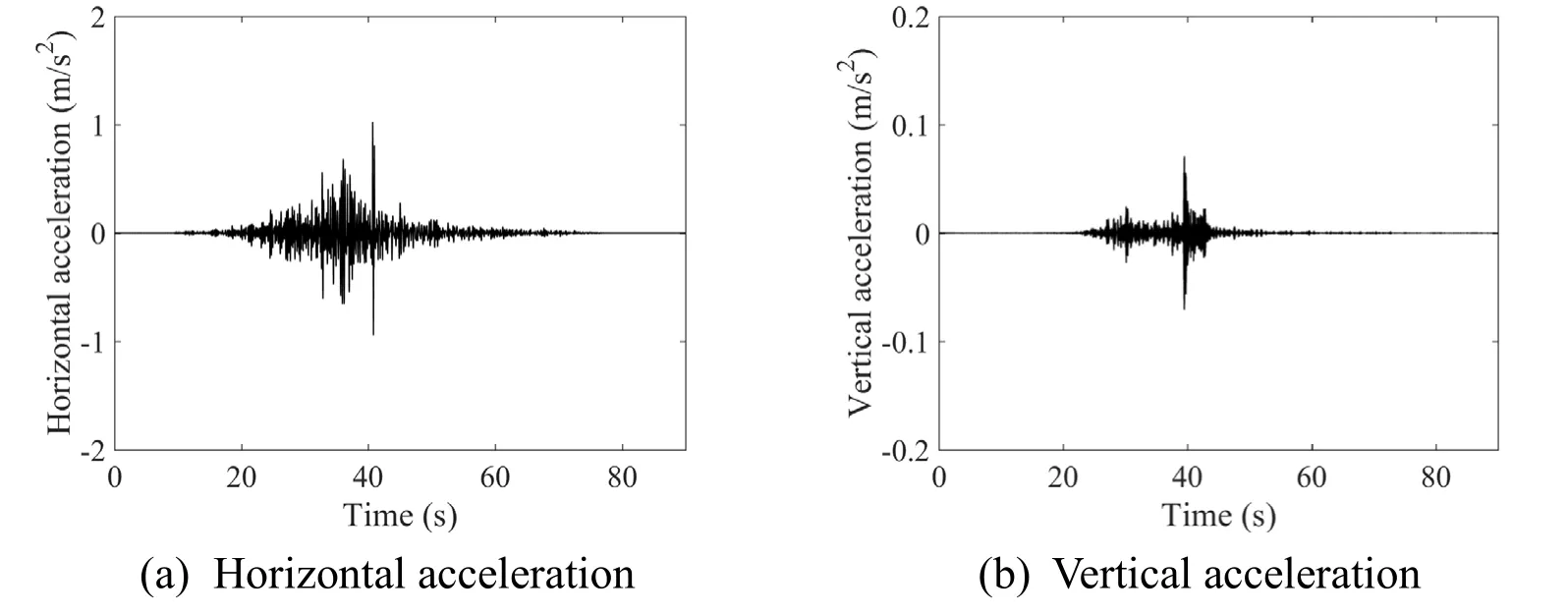
Figure 12:Time history top acceleration response of the 3D isolated facility under case No.1,NGA-1 earthquake input (Soil type I0,minor input)
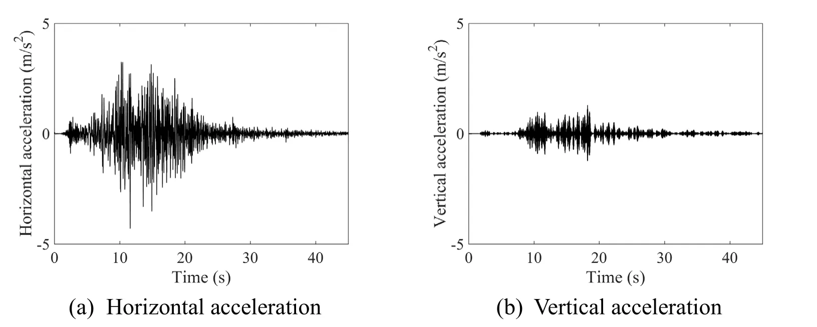
Figure 13:Time history top acceleration response of the 3D isolated facility under case No.4,NGA-1 earthquake input (Soil type I0,major input)
For nonlinear isolation system,the dynamic character is largely dependent on the response amplitude of the system,and this is evident in the horizontal direction.The horizontal isolation displacement increases with larger seismic excitations,thus resulting in smaller equivalent stiffness and longer isolation period to obtain better isolation effect due to the yielding behavior of the rubber isolator.However,for the vertical QZS isolation system,the stiffness of the system would increases with larger vertical displacement,which shows an opposite behavior to the horizontal system.The hardening behavior of the QZS system would result in slightly less effective isolation but it can restrain overly large vertical displacement thus to help control the overturning motion.Another significant difference between horizontal and vertical isolation system is that the relative acceleration response variance of QZS system is larger.
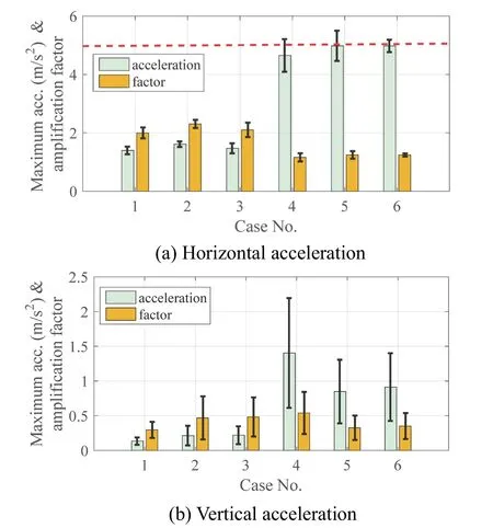
Figure 14:Maximum top acceleration response (mean and standard deviation) and amplification factor of the 3D isolation system
4.4 Impact effect analysis
To evaluate the impact effect on the 3D isolation system,half sine pulses are adopted in the numerical simulations shown in Fig.15.The magnitude of the pulse in the vertical direction is 550 g,and the horizontal direction is 200 g.The duration time of the pulses is 10 ms.Considering the pre-applied gravity and the response after the pulse,the analysis time is 1 s,and the analysis time step is 1×10⁻⁶s.The beginning of the impact effect is set at the middle of the analysis time.
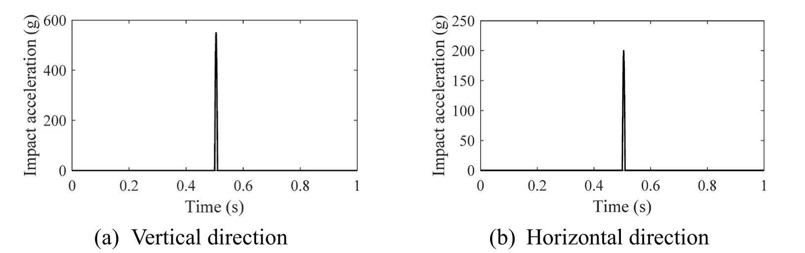
Figure 15:Half sine pulse input
Acceleration at the top of the facility and the displacement time history response in vertical and horizontal directions are given in Figs.16 and 17.Results indicate that,under the strike of the impact,the 3D isolation system can have an optimal impact reduction effect,and the vertical reduction effect is superior to the effect in the horizontal direction.The vertical acceleration peak is 930 m/s2,the AF value (ratio between the peak response and the peak input) is 0.17.The horizontal acceleration peak is 631 m/s2,the corresponding AF value is 0.32.The after strike response also indicates that while the acceleration response diminishes fast,it would take a longer time for the isolation system to recover to its origin position.
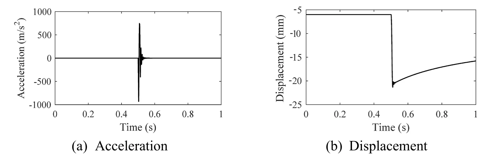
Figure 16:Impact response in vertical direction
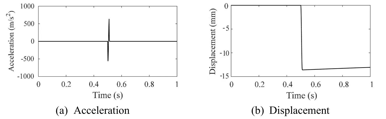
Figure 17:Impact response in horizontal direction
5 Conclusions
This paper proposes a novel 3D isolation system for the facility with a large aspect ratio.For vertical isolation,the QZS system is adopted accompanied with vertical viscous dampers to restrain overturning motion.The traditional elastomeric bearing is designed for the horizontal isolation.Numerical investigations on seismic and impact response of the isolated facility are performed using OpenSees software,main conclusions are drawn as follows,
(1) The proposed 3D isolation system can both have satisfactory seismic isolation effect in horizontal and vertical directions.The peak acceleration response is under well control,the maximum horizontal deformation is within safe range.By adding linear viscous dampers,no uplift effect of the isolator occurs in the vertical direction.Besides,the response variance of the vertical QZS system is more significant than horizontal elastomeric isolation system.
(2) The seismic response behavior of the 3D isolation system would vary with the different earthquake selections and input magnitudes.Generally,the earthquakes with the longer natural period would be disadvantageous to isolation systems,especially for the isolation drift.The dynamic mechanic properties of the QZS and elastomeric isolation system are displacement-dependent,thus the input magnitude would also significantly influence the isolation effect of the system.
(3) The impact effect is considered using half sine pulses,and it is also numerically proved that the 3D isolation system can have a significant reduction effect for the impact both in horizontal and vertical directions.The vertical isolation system has a slightly superior isolation effect to the horizontal isolation system under the impact effect.
Acknowledgement:The authors acknowledge the financial support from National Natural Science Foundation of China (Grant No.51878502).
 Computer Modeling In Engineering&Sciences2019年9期
- Computer Modeling In Engineering&Sciences的其它文章
- Determination of Working Pressure for Airport Runway Rubber Mark Cleaning Vehicle Based on Numeric Simulation
- Experiment and Simulation for Controlling Propagation Direction of Hydrofracture By Multi-Boreholes Hydraulic Fracturing
- Coupling of Peridynamics and Numerical Substructure Method for Modeling Structures with Local Discontinuities
- Structural Finite Element Software Coupling Using Adapter Elements
- Real-Time Hybrid Simulation of Seismically Isolated Structures with Full-Scale Bearings and Large Computational Models
- The Behavior of Rectangular and Circular Reinforced Concrete Columns Under Biaxial Multiple Excitation