Fragility Assessment of Pre-Northridge Steel Moment Frames Using Finite-Length Plastic Hinge Elements and Concentrated Plasticity Fracture Elements
Filipe L.A.Ribeiro,Andre R.Barbosa and Luis C.Neves
Abstract: Although pre-Northridge earthquake steel moment resisting frame buildings have been shown to be susceptible to brittle connection failures,they still represent a large fraction of the existing steel buildings in the United States of America.In this study,the performance of the 3- and 9-story Los Angeles pre-Northridge SAC buildings are analyzed considering ductile and brittle beam-column connection failures,and their uncertainty.This paper contributes to understanding the influence of uncertainty associated with connections brittle fracture on building interstory deformation capacity and its impact on bias and variability of fragility functions and loss assessment.The results show that considering brittle connections leads to significantly larger drift demands and to higher repair costs,particularly under intense ground shaking.New fragility curve parameters are derived that account for the effect of the uncertainty of the strength and deformation capacity of brittle connections.
Keywords: Brittle fracture,finite-length plastic hinge,fragility curves,repair cost ratio,welded-flange connections.
1 Introduction
Prior to the 1994 Northridge earthquake,welded steel construction was widely accepted in seismic regions and was especially common in the United States (US) West Coast.In this period,most steel moment frames (SMF) were designed and constructed using welded-flange-bolted-web (WFBW) c onnections.Fig.1 shows an example of this type of connection using complete joint penetration (CJP) groove weld connecting beam flanges to the column flanges and a shear tab connecting the beam web to the column flange.Following the 1994 Northridge and 1995 Kobe earthquakes,brittle fractures in or around the groove weld between the beam bottom flange and the column flange were observed [Youssef,Bonowitz and Gross (1995)].
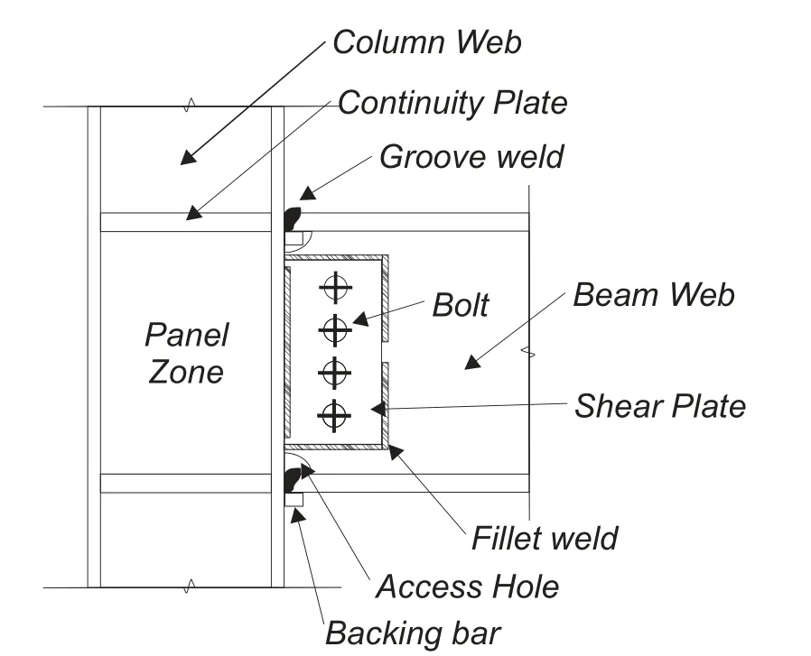
Figure 1:Typical pre-Northridge WFBWconnection detail
Youssef et al.[Youssef,Bonowitz and Gross (1995)],reporting on surveys of steel buildings,showed that 70 to 80%of the damage in connections occurred in the beam bottom flange,while damage in shear connections was quite rare.In addition,experimental research[Youssef,Bonowitz and Gross(1995);Dames&Moore Inc.(1998)]conducted after the 1994 Northridge earthquake confirmed that WFBWconnections are prone to brittle fracture and exhibit low ductility.Based on observed damage modes,Maison et al.[Maison and Bonowitz(1999)]state that,for WFBWconnections,it suffices to model brittle failure at the beams ends in the beam-column flexural connection,as progress of fracture to the columns was very rare.
Several numerical studies investigated the SAC Project Los Angeles buildings[Luco and Cornell(2000);Lee and Foutch(2002);Wang and Wen(2000);Xu and Ellingwood(2011)]using models implemented in DRAIN-2DX and IDASS[Prakash,Powell and Campbell(1993);Kunnath(1995);Uang,Yu,Sadre et al.(1995)].Several authors[Luco and Cornell(2000);Shi and Foutch(1997);Prakash,Powell and Campbell(1993)]stated that,although considering failure of connections consistently increases displacements,the magnitude of the increase varies among different building typologies.In these studies,connections were simulated using the bilinear model shown in Fig.2(a),in which the plastic rotationθfis the main parameter related to fracture.In addition,pre-yield failures resulting from fracture of the bottom beam flange can occur before the nominal plastic momentMyis reached.This could be taken into account through the introduction ofMf,as shown in Fig.2(b).It is worth noting that pre-yield fracture is often neglected since Luco et al.[Luco and Cornell(2000)]have shown that pre-yield fractures have almost no effect on story drift demands.In these studies,the properties of connections are assumed deterministic and constant over the entire building.However,the fracture rotation depends on the quality of the welding,which varies significantly across and within buildings.
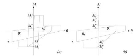
Figure 2:Fracture model(adapted from Luco et al.[Luco and Cornell(2000)])
Based on works developed in the past 20 years,the main objective of this work is to evaluate the impact of uncertainty in connection deformation capacity on the performance of pre-Northridge steel buildings,which still represent a large fraction of existing buildings in the US.To achieve this,it is necessary to disaggregate the uncertainties associated with connection deformation capacity from uncertainty associated with earthquake record-to-record(RTR)variability.Moreover,the structural model used must be capable of simulating the nonlinear behavior of both the beam and the connection independently,as member empirical laws and connection fracture models are commonly derived in separate experimental tests.Thus,finite-length plastic hinge(FLPH)elements are used to simulate beam behavior and concentrated plastic hinge(CPH)springs to simulate brittle connections.As a case study,the seismic performance of the 3-and the 9-story Los Angeles SAC building models,developed in OpenSees,is analyzed.
2 Methods
2.1 Modeling
Beams are modeled using(1)Finite-Length Plastic Hinge(FLPH)elements[Scott and Fenves(2006);Ribeiro,Barbosa,Scott et al.(2015)]for simulating beam nonlinear response,including strength and stiffness deterioration of the beams,and(2)zero-length springs to simulate the nonlinear behavior of connections.Columns are modeled using force-based fiber-section distributed plasticity finite elements,a common assumption as the SAC buildings have rather stocky columns.All models are developed using OpenSees.
The Bilin and Pinching models(ModIMK models)[Ibarra and Krawinkler(2005);Lignos(2008)]are used to model beam plastic hinges(HS sections in Fig.3)and connections(ZLS springs in Fig.3),respectively,using the implementation presented in Ribeiro et al.[Ribeiro,Barbosa and Neves(2017)].The parameters assigned in the analysis are obtained from empirical laws proposed in Lignos et al.[Lignos and Krawinkler(2011)].
Due to the asymetry of the connection,different fracture rotations for positive(θf+)and negative(θf-)bending are typically defined.The difference in the absolute value of the positive and negative rotations is mainly due to the influence of slab and constructional process of these type of connections.The constructional process usually requires backup bars and access holes(Fig.1)to allow for welding of the bottom beam flanges to the column flanges,which usually decrease the positive bending rotation capacity.After fracture,the behavior of the connection model includes a softening branch over a small increment of rotation,which is assumed equal to 0.002 rad,so that numerical convergence is not compromised;the softening branch simulates phenomena such as web,flange,or weld tears.After fracture of the top or bottom beam flange,the strength in the opposite flange remains almost unchanged.Fig.3 illustrates main components of the developed model.
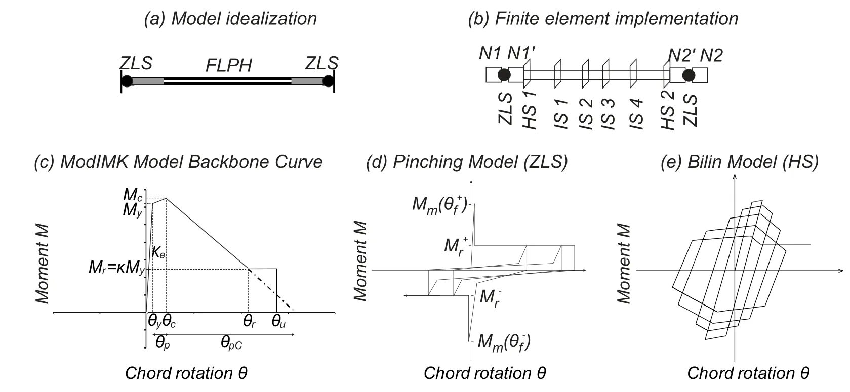
Figure 3:Conceptual description of the proposed modeling approach
2.2 Validation through benchmarking with experimental testing results
A detailed benchmarking has been made available at Ribeiro et al.[Ribeiro,Barbosa,Kameshwar et al.(2018)]and only the main findings are summarized here.Five experimental tests developed as part of the SAC Project Phase I[SAC(1996)]and Phase II[SAC(1998)]were used to benchmark the proposed modeling approach.A very limited number of tests defining the post-fracture behavior were found in the literature,so that one additional test reported in Bernuzzi et al.[Bernuzzi,Calado and Castiglioni(1997)]was used to benchmark the post-fracture behavior.Results from the benchmarking study indicate that the proposed modeling approach captures well the post-fracture behavior of the damaged connections.However,the success of the benchmarking depends greatly on the value assigned to the fracture rotation.
2.3 Probabilistic modeling of connection fracture
The connection fracture rotation,θf,is herein defined as a random variable.However,as discussed above there are very limited experimental tests on these pre-Northridge steel moment connections,and thus the probabilistic models were defined using a combination of lab results and expert judgment.Based on the limited tests available,θfis defined following a log-normal distribution[Bjornsson and Krishnan(2012)]for the top and bottom beam flange.Considering the value of plastic rotation capacity observed at first fracture in the SAC Phase I laboratory tests[SAC(1997)],the mean positive fracture rotation is taken asθf+=0.015 rad and the standard deviation is estimated to be 0.007 rad.
Due to the lack of data regarding top flange fracture,the negative fracture rotation is assumed fully correlated with the positive rotation,θf-=2×θf+.This is supported by laboratory tests of full-scale beam-column connections that were continued beyond first(bottom)beam flange fracture[Maison and Bonowitz(1999);Lee,Stojadinovic,Goel et al.(2000)].
Once fracture occurs,the positive or negative bending moment capacity is reduced to 30%Mp,whereas the connection retains its full moment capacity in the opposite bending direction[Anderson,Johnston and Partridge(1996)].The reduction to 30%is taken as a deterministic value and pre-yield fractures are not considered[Luco and Cornell(2000)].While the properties of connections vary within a building,it is expected that correlation between different connections exist,due to common workmanship,quality control and equipment used.Extensive data from structures would be required to estimate this correlation[Kazantzi,Vamvatsikos and Lignos(2014)],which is lacking.Based on Idota et al.[Idota,Guan and Yamazaki(2009)],a correlation coefficient of 0.70 is assumed.
Three pinching parameters that control the point at which reloading starts also need to be defined in the post-fracture connection behavior[Ribeiro,Barbosa and Neves(2017)].Two of them correspond to the ratio of moment at which reloading starts in positive and negative direction,respectively,and are taken equal to 0.3(Fr+=Fr-=0.3).The third parameter,which corresponds to the ratio of rotation at which reloading starts,is considered equal to 0.8(Apinch=0.8).The sensitivity of the structural response to variation in these parameters is reported in later sections.
2.4 Analysis methodology
The drift demands for each structure modeled with brittle beam to beam-column joint connections,here forth designatedbrittle structural model,are compared with the results for the structure modeled with perfectly-ductile connections here forth designated asductile structural model.Ten and thirteen different intensity levels of the seismic action are considered for the brittle and ductile structural models,respectively.These are obtained by scaling ground motion records from the SAC Steel Project 10/50(10%in 50 years probability of exceedance)ground motion set,with factors ranging from 0.3 to 1.8 for the brittle structural model and from 0.3 to 3.0 for the ductile structural model.For the ductile structural model,three additional intensity levels(with scale factors 2.3,2.6,and 3.0)are required to obtain drifts similar to those observed using the brittle structural model.For reference,the records scaled by 1.0 and 1.5 correspond to the Design Basis Earthquake(DBE)and the Maximum Considered Earthquake(MCE)intensity levels,respectively.The peak interstory drift ratio(IDR)is taken as the engineering demand parameter that best describes the structural response as it offers a compromise between local and global structural behavior.
Latin Hypercube Sampling[McKay,Beckman and Conover(1979);Olsson,Sandberg and Dahlblom(2003)]is used to generate two-hundred building samples.According to preliminary sensitivity studies this number of samples is sufficient to guarantee convergence of building displacements.Nonetheless,for achieving convergence at accelerations a larger number of samples would be required.
For each analysis,the Newton-Raphson method is used to solve the nonlinear system of equations at each time step.An adaptive scheme was implemented to overcome possible convergence problems[Ribeiro,Barbosa and Neves(2014)].To reduce the computational time required to perform the analyses,a single-core high-throughput computing framework based on HTCondor[Thain,Tannenbaum and Livny(2005)]implemented at Oregon State University was used.
Fragility curves and probabilistic distributions of repair cost ratio(RCR)of the damaged buildings are estimated based on the set of analyses carried out on the brittle and ductile structural models.Fragility curve and RCR computation allows for the assessment of the influence of connection fracture on building response and the influence of connection fracture uncertainty on the collapse risk.Fragility curves are developed using maximum likelihood estimates[Baker(2015)].Four different damage states(DS;slight,moderate,extensive,complete)are considered as defined in FEMA-351[FEMA-351(2000)].The values of the peak IDR thresholds defining the different DS are listed in Tab.1.The limit state threshold values of IDR used are supported by other studies,such as Maison et al.[Maison and Bonowitz(1999)].Table 1 also lists the RCR associated with each DS.The average RCR of the building at a given intensity level IL is given by:

The values of the RCR for each DS and the total cost of the building models are estimated following FEMA-351[FEMA-351(2000)].The total replacement cost are set at$1.6 Million and$5 Million for the LA3 and LA9 buildings,respectively.

Table 1:Maximum values defining damage limit state thresholds
3 Case study
3.1 Building modeling and ground motion records
The SMF buildings studied in this work are the three(3-)and 9-story buildings(denoted LA3 and LA9,respectively),developed as part of the SAC steel project.In both buildings,external frames were designed to resist the lateral seismic loads while interior frames were designed as gravity frames.Fig.4 shows one of the moment resisting frames in the N-S direction.Both buildings have spans of 9.15 m in both directions.The 3-story building does not have basement,whereas the 9-story building has one basement level.The story height is constant and equal to 3.96 m,except for the basement and first levels of the taller building,which have story heights of 3.65 and 5.49 m,respectively.A detailed description of the buildings is presented in FEMA-355C[FEMA-355C(2000)]and Luco[Luco(2002)]and additional summaries are available in Ribeiro et al.[Ribeiro,Barbosa and Neves(2014);Kameshwar,Ribeiro,Barbosa et al.(2019)].
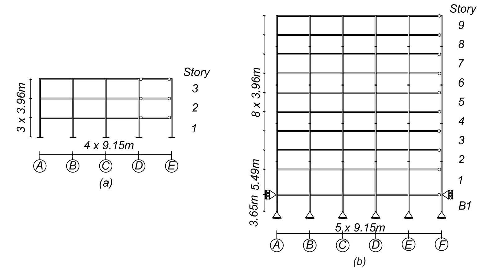
Figure 4:(a)LA3 building;and(b)LA9 building
Ten ground motion records,corresponding to the largest PGA records in the SAC Steel Project 10/50 ground motion set are used[Somerville,Smith,Punyamurthula et al.(1997)].The median pseudo-acceleration response spectra of the selected ground motions are compared to the ASCE 7-10 design spectrum in Fig.5.The two are very close and similar spectral acceleration values are obtained at the fundamental periods of both buildings.
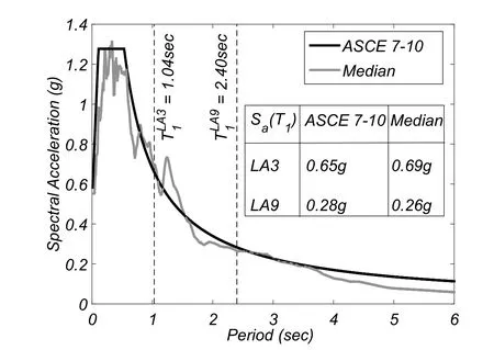
Figure 5:Median response spectrum of the 10/50 SAC ground motion set
3.2 Structural models
A centerline model of each of the SMFs is developed using OpenSees.Geometric nonlinearities are accounted for by considering aP-Δleaning column carrying half of the building’s weight.A rigid diaphragm is assumed for each floor.Masses and loads are applied to beam-column joints.Similarly to the approach in FEMA-355C[FEMA-355C(2000)],Rayleigh damping is assigned to the models.As described in Erduran[Erduran(2012)],a damping ratio of 2%is assigned to the first mode(T1LA3=1.04sandT1LA9=2.40s)and a mode with period close to 0.2s,which corresponds to LA3 model third modal period and the LA9 model fifth modal period.Soil-structure interaction is not considered.For beams,cyclic deterioration and connection fracture are considered to be the most relevant phenomena.In this context,the modeling approach presented in Fig.3 is employed here to simulate beam and connection behavior.The connections are defined according to the fracture model presented in Section 2.3.The beam plastic hinge flexural behavior is simulated through the use of theBilinmodel,whose parameters follow Lignos et al.[Lignos and Krawinkler(2011)]empirical expressions and a plastic hinge length ofLp=L/16 is considered[Ribeiro,Barbosa,Scott et al.(2015)].
For columns,the critical phenomena to be modeled is the interaction between bending moment and axial force[Ribeiro,Barbosa and Neves(2014)].Consequently,columns are modeled by considering a force-based fiber-section distributed plasticity beam-column finite elements with six integration points and an elasto-plastic constitutive law with a 3%hardening rate assigned to each fiber.
The ductile connection models have been extensively validated using both nonlinear static and nonlinear dynamic time-history response analysis[Ribeiro,Barbosa and Neves(2012,2014);Kameshwar,Ribeiro,Barbosa et al.(2019)].As a consequence,and considering the validation of the fracture model carried out in this work,the proposed model is consistent with experimental results and includes realistic effects of the deterioration of beam properties in the analysis.
4 Results
4.1 Deterministic performance assessment
A first assessment to the performance of the buildings was carried out considering a deterministic connection fracture rotation corresponding to its mean value,θf+=0.015 rad,under all ground motions at the DBE and MCE intensity levels.Results for the median peak IDR,the median percentage of fractured connections(PFC),and the increase in the median peak IDR(relatively to the ductile case)are presented in Tab.2.
For the LA3 building model,a significant increase in the peak IDR is observed for both intensity levels(80%and 146%for DBE and MCE,respectively).The increase in peak IDR correlates well with the PFC of both buildings.For the LA9 building model,a negligible increase(approximately 1%)in peak IDR is obtained for the brittle structural model relative to ductile structural model for the DBE intensity level and a relatively small increase(17%)is recorded for the MCE level.Some other works where buildings similar to those studied herein are analyzed[Luco and Cornell(2000);Maison and Bonowitz(1999);Islam(1996);SAC(1995);Uang,Yu,Sadre et al.(1995)]have reported results for peak IDR(and PFC when available)close to the ones obtained in this deterministic assessment,indicating that the FE models developed are reasonably well benchmarked with existing data.

Table 2:Deterministic performance assessment results obtained consideringθ+f=0.015 rad for all connections
In order to evaluate the impact of connection fracture rotation on performance,pushover analysis was carried out considering 7 sets of connection properties:constant over the entire building and equal to 0.020,0.015,0.010,and 0.007 rad;two random samples;and ductile connections.Fig.6 shows that forθ+f=0.020 rad the maximum base shear is close to the perfectly ductile connection model case.However,a brittle collapse occurs due to the fracture of several connections at the same time and,consequently,numerical instability is observed during the analysis.For lower values of connection fracture rotations(0.015,0.010,0.007 rad)the base shear associated with collapse decreases.Failure is also characterized by a brittle collapse of the structure.
Fig.6 also shows results when the fracture rotation capacities are randomly assigned to the connections of the buildings.In this case,the base shear associated with collapse is between those associated withθ+f=0.020 rad andθ+f=0.007 rad.The capacity curve is characterized by several progressive jumps,corresponding to the progressive failure of individual connections.This is clearly seen in the LA9 building responses(Fig.6(b))but not as evident in the LA3 building responses(Fig.6(a))due to the reduced number of connections.
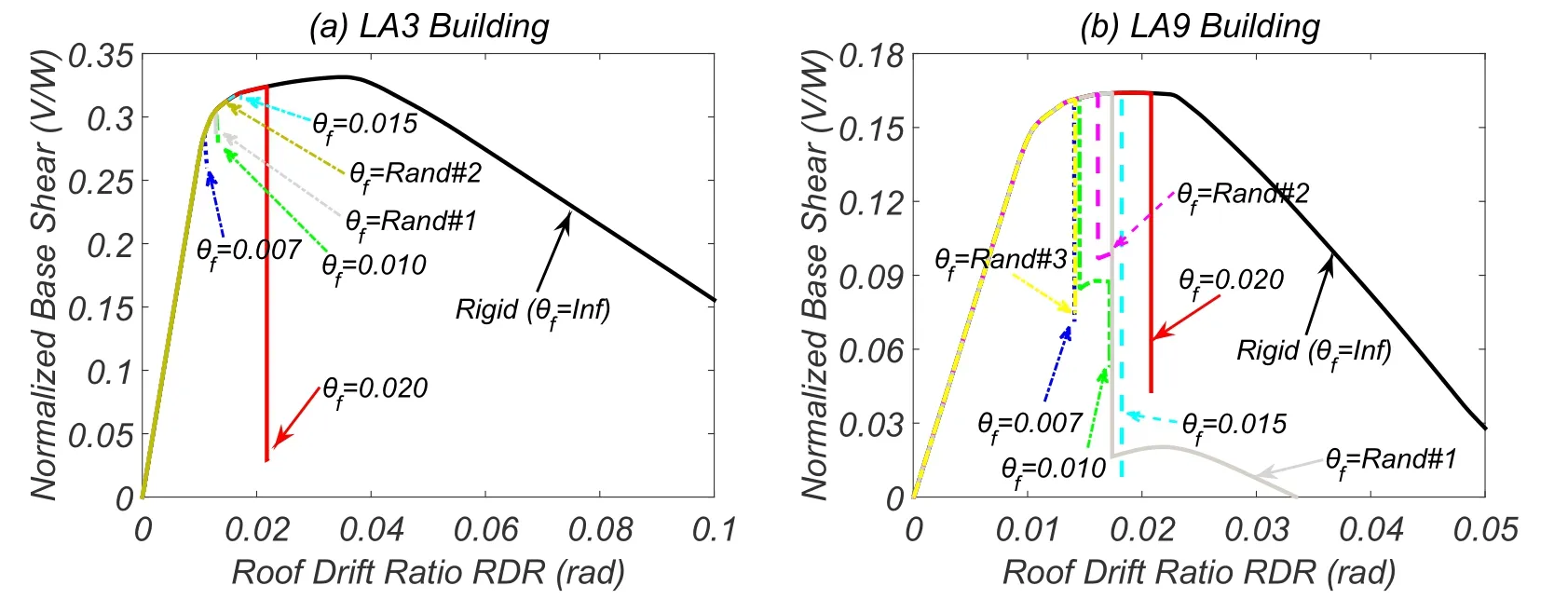
Figure 6:Pushover analysis with various connection fractures rotations:(a)LA3 building;and(b)LA9 building
Fig.7 shows results of the nonlinear time-history response analysis performed on the same models subjected to the ground motion LA04.Ifθ+f=0.020 rad,no connection fails in either buildings and,as a consequence,the peak IDR is equal to that obtained with the perfectly ductile connection model.When the value of the fracture rotation decreases,the peak IDR increases by more than 100%for some cases.For the LA3 building the peak IDRassociated with=0.010 rad is larger than the one obtained withθf=0.007 rad,which is due to particular ground motion acceleration history and the time at which connections fractures,which is a function of the fracture rotation.The analyses conducted with random fracture rotations showed that the obtained peak IDRs are within the interval defined by the results of the deterministic analyses.
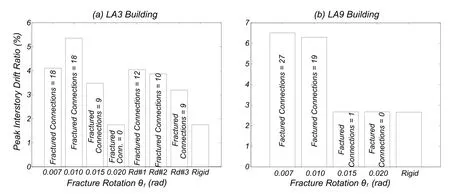
Figure 7:Nonlinear dynamic analysis with different connection fracture rotations:(a)LA3 building;and(b)LA9 building
Finally,the sensitivity of the peak IDR of the LA9 building to the variation of the pinching parameters was also analyzed.Although results are not detailed herein for sake of brevity,it is worth referring that variation inFrdid not introduce significant variation in peak IDR.The parameterApinch(i.e.,the rotation fraction at which reloading starts)did influence the peak IDR,but ever so slightly.Consequently,these pinching parameters were assumed deterministic in subsequent analyses.
4.2 Probabilistic analysis
4.2.1 Performance assessment:LA3 building
The median peak IDRof the structure under the ten intensity levels for the brittle connection model and the thirteen intensity levels for the perfectly ductile connection model are presented in Fig.8.Each intensity level is associated with a box describing the variability of the results.On each box,the central mark is the median,the edges of the box are the 25thand 75thpercentiles,while the whiskers extend to 2.7×σ,assuming a normal distribution.The outliers are plotted individually as red dots.The median peak IDR obtained for the DBE and the MCE intensity levels are 4.31%and 8.14%,respectively.These values represent an increase,relatively to the perfectly ductile connection model case,of 76%and 114%,respectively.The ratio between the peak IDR’s obtained with the brittle and perfectly ductile connection models are represented in Fig.9.The results associated with the brittle connection model have a much larger dispersion,namely for intensity levels up to the MCE intensity levels.Above that,the dispersion(see Fig.9(b))is approximately the same between the two models.
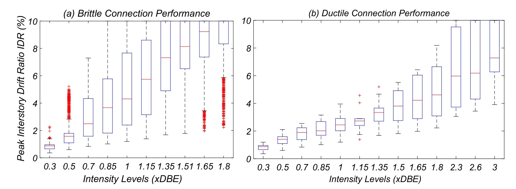
Figure 8:LA3 building-peak IDR associated with:(a)brittle connection model;and(b)perfectly ductile connection model
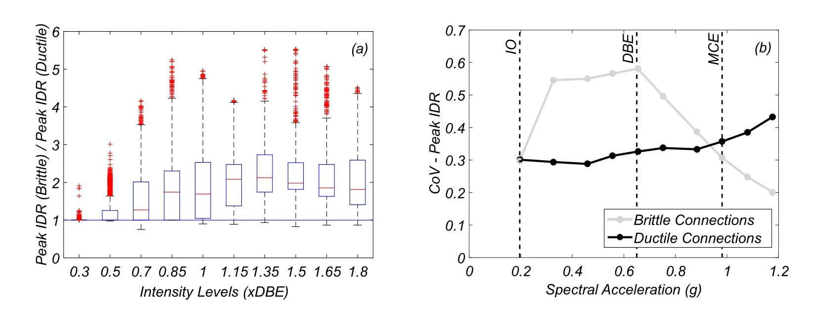
Figure 9:LA3 building-(a)Ratio of the peak IDR obtained with the brittle connection model and the perfectly ductile connection model;and(b)coefficient of variation of the peak IDR at each intensity level for the two models
In Fig.10 the PFC associated with the LA3 building is represented.For the DBE intensity level the median PFC is 66%,while for the MCE level is 100%.
4.2.2 Performance assessment:LA9 building
The median peak IDR is presented in Fig.11 for the various intensity levels.The median peak IDR obtained for the DBE and the MCE intensity levels is 2.47%and 3.84%,respectively.These values represent an increase,relatively to the perfectly ductile connection model case,of 4%and 16%,respectively.The ratio between the peak IDR’s obtained with the brittle and perfectly ductile connection models are represented in Fig.12.For the LA9 building,the increase in the peak IDR due to the consideration of brittle connections is much lower than that associated with the LA3 building.This is a result of the homogenous interstory drift pattern along the building’s height.In fact,there is no significant concentration of deformation at any height,due to the building’s capacity to redistribute damage,as will be discussed below.
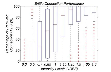
Figure 10:LA3 building-percentage of fractured connections(PFC)
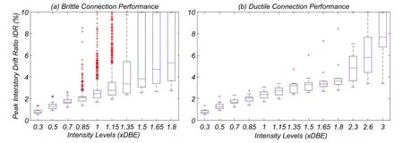
Figure 11:LA9 building-peak IDR associated with:(a)brittle connection model;and(b)perfectly ductile connection model
In Fig.13 the PFC associated with the LA9 building is represented.Although some analyses report a large number of fractured connections,the median value of the PFC associated with the DBE intensity level is 0%,which indicates that for this building and intensity the connections present low risk of fracture.For the MCE level,PFC is 8%,which is still a relatively low value.
In order to further investigate the distribution of damage across the LA9 building models,the distribution of fractured connections is represented as a function of the intensity level in Fig.14.The size of a circles placed at each connection illustrates the percentage of analyses in which a fracture was observed in a connection out of the total number of analyses performed for each intensity level,which was 2000.This percentage is represented using the acronym NFC to distinguish it from PFC(percentage of fractured connections in a building for a single analysis).The largest size of the circles per intensity level is scaled to the maximum number of analyses in which fractures were observed,as indicated in the scale bar at the top of the figure.For the first four intensity levels,fractured connections are only observed in floor levels 7 and 8.For other intensity levels the number of analyses where fractured connections are observed tend to concentrate between floors 1 and 3 or floors 7 and 8.
Fig.15 shows the relationship between the peak IDR and the PFC.A clear trend is observable and a linear regression fits very well the results.
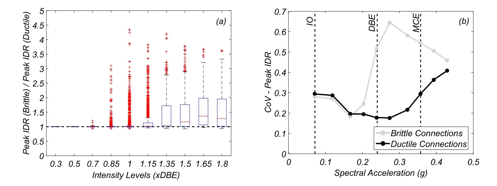
Figure 12:LA9 building-(a)Ratio of the peak IDR obtained with the brittle connection model and the perfectly ductile connection model;and(b)coefficient of variation of the peak IDR at each intensity level for the two models
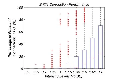
Figure 13:LA9 building-Percentage of fractured connections(PFC)
4.2.3Fragilityanalysis
Fig.16(a) shows fragility curves obtained for the LA3 building.These curves indicate that for the first two DS (Slight and Moderate damage states) the influence of connection fracture is negligible,as a results of the low number of fractures that occur at this level of deformation.For the Extensive DS,the influence of connection fracture is clearly visible,significantly increasing the probability of exceeding this DS.Finally,for the Complete DS the difference between the fragility curves associated with the brittle connection model and the perfectly ductile connection model is worth highlighting.The observed differences have repercussions on the costs associated with repairing the building after the earthquake,which are represented in Fig.16(b).For the DBE intensity level,a difference in RCR of approximately 35% exists between the brittle model the perfectly ductile model,which would lead to an expected difference of $560k in the total repair cost.
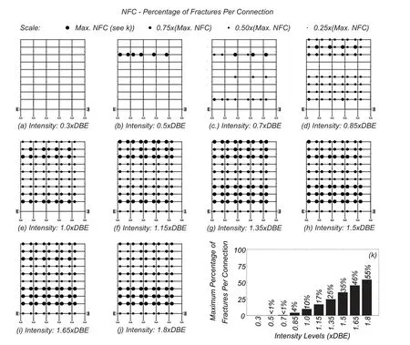
Figure 14:LA9 building-percentage of analyses in which fracture was observed in a connection out of the total number of analyses performed for each intensity level(2000)
Fig.17(a)shows the fragility curves obtained for the LA9 building.These curves indicate that the influence of connection fracture is negligible for the first three DS(Slight,Moderate,and Extensive damage states)as a result of the low number of fractures that occur at this level of deformation.However,for the Complete DS the influence of connection fracture is clearly visible,increasing the probability of exceeding the threshold value of peak IDR.Nevertheless,the differences in the RCR(see Fig.17(b))are much smaller than those obtained for LA3 building due to the smaller differences in peak IDR due to connection fractures.
Tab.3 and Tab.4 show the computed fragility curve parameters,which can be useful for future performance-based studies.The uncertainty in the perfectly ductile connection model arises from the record-to-record variability(βR T R),whereas the uncertainty in the brittle connection model is related to the RTR variability and the connection fracture uncertainty(β2=βR2T R+βC2onn).
The obtained results indicate that only for the Complete DS there is an increase in the uncertainty due to connection fracture uncertainty(βC onn=0.17 for LA3 andβC onn=0.15 for LA9),which is approximately 40% of the total variability value.
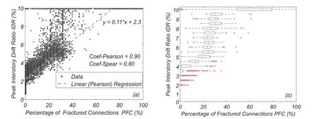
Figure 15:LA9 building-peak IDR as a function of the percentage of fractured connections (PFC)
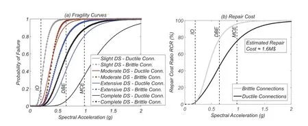
Figure 16:LA3 building-(a)fragility curves;and(b)repair cost ratio(RCR)estimation
5 Conclusion
This work focuses on the response assessment of steel moment frames(SMF)designed according to pre-Northridge codes considering probabilistically defined brittle connection behavior.During the 1994 Northridge earthquake many brittle fractures were observed,with significant impact on consequences to users and repair costs.Although these connections are rare in new buildings,the pre-Northridge buildings represent a large fraction of the existing buildings in the US.
The 3-and the 9-story Los Angeles SAC buildings,which were designed according to pre-Northridge codes[UBC(1994)]are studied in this work,considering the uncertainty in both ground motion records and connection properties.For each building,numerical models are developed considering brittle beam-column connection failure and perfectly ductile connections.
Results obtained in this work show that:

Table 3:Fragility curve parameters(considering lognormal distribution)associated with LA3 building
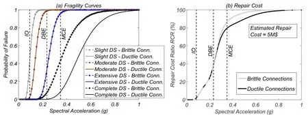
Figure 17:LA9 building-(a)fragility curves;and(b)repair cost ratio(RCR)estimation
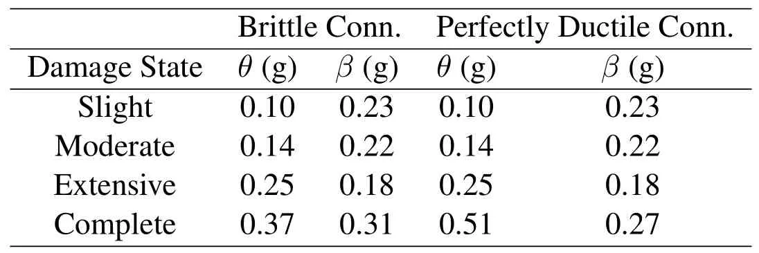
Table 4:Fragility curve parameters(considering lognormal distribution)associated with LA9 building
·The consideration of brittle beam end to beam-column joint connection leads to significantly larger drift demands,and consequently,to higher repair cost ratios.An increase of 114%in the peak interstory drift ratio is obtained for the Maximum Considered Earthquake(MCE)intensity level for the 3-story building,whereas a smaller increase is observed(approximately 16%)for the for 9-story building.This smaller impact of the consideration of brittle connections on the 9-story building is as a consequence of the capacity of the building to distribute damage.The LA9 building exhibited a larger capacity to redistribute damage.
·The larger drift demands obtained due to the brittle behavior of connections lead to an increase of 75%and 26%in the median repair cost ratio for the DBE and MCE intensity levels,respectively,for the LA3 building.For the LA9 building,this increase is lower,being negligible for the DBE and approximately 9%for the MCE intensity levels.Additionally,the analysis methodology applied in this work allowed for the separation between the record-to-record and connection rotation capacity uncertainty in the estimation of fragility function parameters.The obtained results indicate that the contribution of the connection capacity uncertainty(β)to building drift response is not significant,when compared to that associated with the ground motion,for all damage states,except for the Complete DS.For the Complete DS,the influence of uncertainty in connection fracture is still much lower than that associated with the ground motion(0.17vs.0.36 for the LA3 building;0.15vs.0.27 for the LA9 building).
·A probabilistically defined connection rotation capacity leads to more realistic building performance assessment.Assuming a deterministic connection capacity(i.e.,connection fracture rotation)equal to its mean value leads to an overestimation of the interstory drift demands of 3%and 14%for the DBE and MCE,respectively,for the LA3 building.For the LA9 building the differences were negligible.
Acknowledgement:The authors are thankful for the support of the National Laboratory of Civil Engineering (LNEC),the New University of Lisbon,the Civil Engineering Research and Innovation for Sustainability (CERIS) Research Center at the University of Lisbon,and the Portuguese Science and Technology Foundation through the fellowship SFRH/BD/777722/2011 to the first a uthor.The a uthors would a lso l ike t o acknowledge the support of Oregon State University through the Endowed Kearney Faculty Scholar for the second author.The support of the University of Nottingham Resilience Engineering Research Group to the third author is gratefully acknowledged.The opinions and conclusions presented in this paper are those of the authors and do not necessarily reflect the views of the sponsoring organizations.
 Computer Modeling In Engineering&Sciences2019年9期
- Computer Modeling In Engineering&Sciences的其它文章
- Coupling of Peridynamics and Numerical Substructure Method for Modeling Structures with Local Discontinuities
- The Behavior of Rectangular and Circular Reinforced Concrete Columns Under Biaxial Multiple Excitation
- Real-Time Hybrid Simulation of Seismically Isolated Structures with Full-Scale Bearings and Large Computational Models
- Structural Finite Element Software Coupling Using Adapter Elements
- Experiment and Simulation for Controlling Propagation Direction of Hydrofracture By Multi-Boreholes Hydraulic Fracturing
- Determination of Working Pressure for Airport Runway Rubber Mark Cleaning Vehicle Based on Numeric Simulation
