Integration of Peridynamic Theory and OpenSees for Solving Problems in Civil Engineering
Quan Gu,Lei Wang and Surong Huang
Abstract:Peridynamics (PD) is a powerful method to simulate the discontinuous problems in civil engineering.However,it may take a lot of effort to implement the material constitutive models into PD program for solving a broad range of problems.OpenSees is an open source software which includes a versatile material library and has been widely used by researchers and engineers in civil engineering.In this context,the paper presents a simple but effective approach to integrate PD with OpenSees by using a Client-Server (CS) software integration technique,such that the existing material constitutive models in OpenSees can be directly used by PD.Two applications are presented to verify the new PD-OpenSees platform.The first one is a plate with a pre-crack subject to horizontal load simulated using a three-dimension (3D) multi-yield-surfaces plasticity model,and the second one is a concrete block with a rectangular hole subject to a uniaxial loading condition simulated using a 3D Cap plasticity model.It shows that the generation/ propagation of cracks of the elastoplastic materials (e.g.,concrete and soil) can be analyzed by combing PD and three-dimensional plasticity constitutive models without compiling/ linking these complex material models into PD program.Thus,the integrated PDOpenSees platform presented herein is potentially capable to solve a wide range of complex problems in civil engineering.
Keywords:Peridynamics,OpenSees,client-server technique,Cap plasticity model,multiyield surface model.
1 Introduction
Peridynamics (PD) is a mechanic theory presented by Silling and co-workers [Silling (2000)] that extends classical continuum mechanics to include discrete particles and growing cracks.The continuum theory is based on the partial differential equations,which requires sufficient smooth deformation field.However,the deformation at the region with cracks or displacement discontinuities is singular and the partial derivatives are not available,which leads to inaccuracy or incapability of the continuum theory.The cracks or displacement discontinuities are commonly encountered in the problems of civil engineering,e.g.,reinforced concrete components.The PD theory is a practically useful method for these problems.The PD theory follows a set of integral equations [Silling (2000)] which does not require a continuous response fields or continuous material space [Silling,Epton,Weckner et al.(2007);Silling and Lehoucq (2010)].The internal force acting on a particle is assumed to be only from the particles that are close enough,i.e.,inside a so-called material horizon.There are two types of PD,i.e.,the bond-based PD and state-based PD.In the bond-based PD,the pairwise force between a particle of interest and a ‘pair’ particle within its material horizon is calculated based on their relative locations in the reference and current configurations.The interaction force is assumed to be along the direction between the two particles and the magnitude can be calculated using a one dimensional (1D) constitutive model.In the bond-based PD,the Poisson ratio is fixed (i.e.,one third or one quarter) for any material,and the plastic incompressibility cannot be considered appropriately [Silling (2000);Gerstle (2015)].In the state-based PD,a deformation gradient at a particle is calculated based on the information of all particles inside its material horizon,i.e.,their relative locations in both undeformed and deformed configurations.A force state may be calculated using 3D material constitutive model based on the deformation.The interaction force vector between two particles does not need to be equal in magnitude and opposite to each other,while they must satisfy the balance of angular momentum.The Poisson ratio can be prescribed for various materials and is not necessary to be fixed [Silling,Epton,Weckner et al.(2007)].Apparently,the application of the state-based PD is more general than that of the bond-based PD.Some elastoplastic material constitutive models (e.g.,Drucker Prager model [Lai,Ren,Fan et al.(2015);Song,Yu and Kang (2018)],Johnson-Holmquist 2 model [Lai,Liu,Li et al.(2018)]) are implemented in the state-based PD for various engineering problems.However,it may still take a lot of effort for researchers to implement new material constitutive models into the PD program.Considering there are abundant material models in the current FEM software,it is interesting to take advantages of these existing models directly and integrate the PD theory and these FEM software platforms in a simple way.
OpenSees (the Open System for Earthquake Engineering Simulation) is an open source software developed since 1997 by the pacific earthquake engineering research (PEER) center,which is widely used in simulating the seismic structural or geotechnical responses [Mazzoni,McKenna,Scott et al.(2006);McKenna (2011)].In the past two decades,OpenSees keeps integrating various material,element,section models and algorithms developed by researchers from all over the world.There are various 1D concrete material models (e.g.,the uniaxial Kent-Scott-Park material model [Kent and Park (1971)]),1D steel models (e.g.,the uniaxial bilinear material model),3D concrete models (e.g.,Cap plasticity model [Sandler,Dimaggio and Baladi (1976);Sandler and Rubin (1979);Hofstetter,Simo and Taylor (1993)]) and 3D soil models (e.g.,the bounding surface hypoplasticity model [Wang,Dafalias and Shen (1990)] and the multi-yield-surface J2 plasticity model [Gu,Conte,Elgamal et al.(2009)]).OpenSees has included a versatile library and been increasingly widely used by researchers and engineers in civil engineering.A simple but powerful tool command language,Tcl,developed by John Ousterhout and coworkers [Ousterhout and Jones (2009)],is used by OpenSees to create the FE models,analyze the models and get the model responses.
However,it is not easy to directly compile and link PD program with OpenSees,since they are both complicated software and are written in Fortran and C++ respectively.In this paper,a simple but effective approach is proposed to integrate PD with OpenSees by using a Client-Server (CS) software integration technique presented by the authors and co-workers [Gu and Ozcelik (2011)].Based on the CS technique,OpenSees is modified using Tcl to be a “material server” that remains in the memory,handles a material object,waits to receive a strain from client,calculates the corresponding stress based on the material constitutive model and sends it back to client.A socket connection between PD client and OpenSees server is achieved by using a simple Tcl network communication channel (or socket) based on TCP/IP or other network protocols (e.g.,UDP).Each material point at a particle in the PD program is a client,which keeps the connection with the material server,sends strain to server and receives stress from the server.Using this approach,the PD program and OpenSees are seamlessly integrated without extra efforts of compiling and linking the two programs.All existing material constitutive models in OpenSees can be directly used by PD.The integration is robust by using the network socket and efficient due to the small data transfer between PD and OpenSees.
Two application examples are presented to verify the PD-OpenSees platform implemented by using the CS technique for solving civil engineering problems.The first one is a plate with a pre-crack subject to horizontal load.The material is simulated using a 3D multiyield-surfaces J2 plasticity model,which is commonly used in geotechnical engineering for simulating behaviors of the clay soil.The second example is a concrete block with a rectangular hole subject to uniaxial loading condition.The 3D Cap plasticity model is used to simulate the concrete behaviors.The examples demonstrate that the generation/propagation of cracks of elastoplastic materials can be simulated efficiently by integrating PD and OpenSees using complex 3D plasticity constitutive models,which may be extremely valuable in solving a wide range of complex problems in civil engineering.
2 Integration of PD and OpenSees based on CS technique
In this section,the basic theory of PD and two commonly used 3D constitutive models in OpenSees used for the applications are illustrated briefly.An integration method based on the CS technique is reviewed to couple PD and OpenSees.
2.1 The PD theory
There are two types of PD,i.e.,the bond-based PD and the state-based PD.The equation of motion for both types of PD has the format as,

whereρis the mass density in the reference configuration,is the acceleration of particle XA,t is time,b is the body force density (refer to Fig.1,whereHXAis a neighborhood of particle XA).In bond-based PD,L( xA,t) is defined as:

in whichf( xA,xB) is a pairwise force that the particle xBexerts on particle xA.As shown in Fig.1,f( xA,xB) is a function of ξ,η andf( xA,xB)= -f(xB,xA).The parameter ξ represents the relative position of the two particles in the reference configuration,and η represents their relative displacement in the current configuration,i.e.,ξAB= XB-XA,ηAB= uB-uA.According to the definition,ξAB+ηABrepresents the relative position vector in the current configuration.VBis a volume of material particle XB.
The force vectorfcan be calculated as follows:

where s is the stretch (scalar) between the two particles,which is defined asrepresents the direction of the force vectorf.The magnitude of the vectorf=f(s)n can be calculated by a 1D material constitutive model.A “horizon”δis used to define the neighborhood of PD particle XA(see Fig.1).
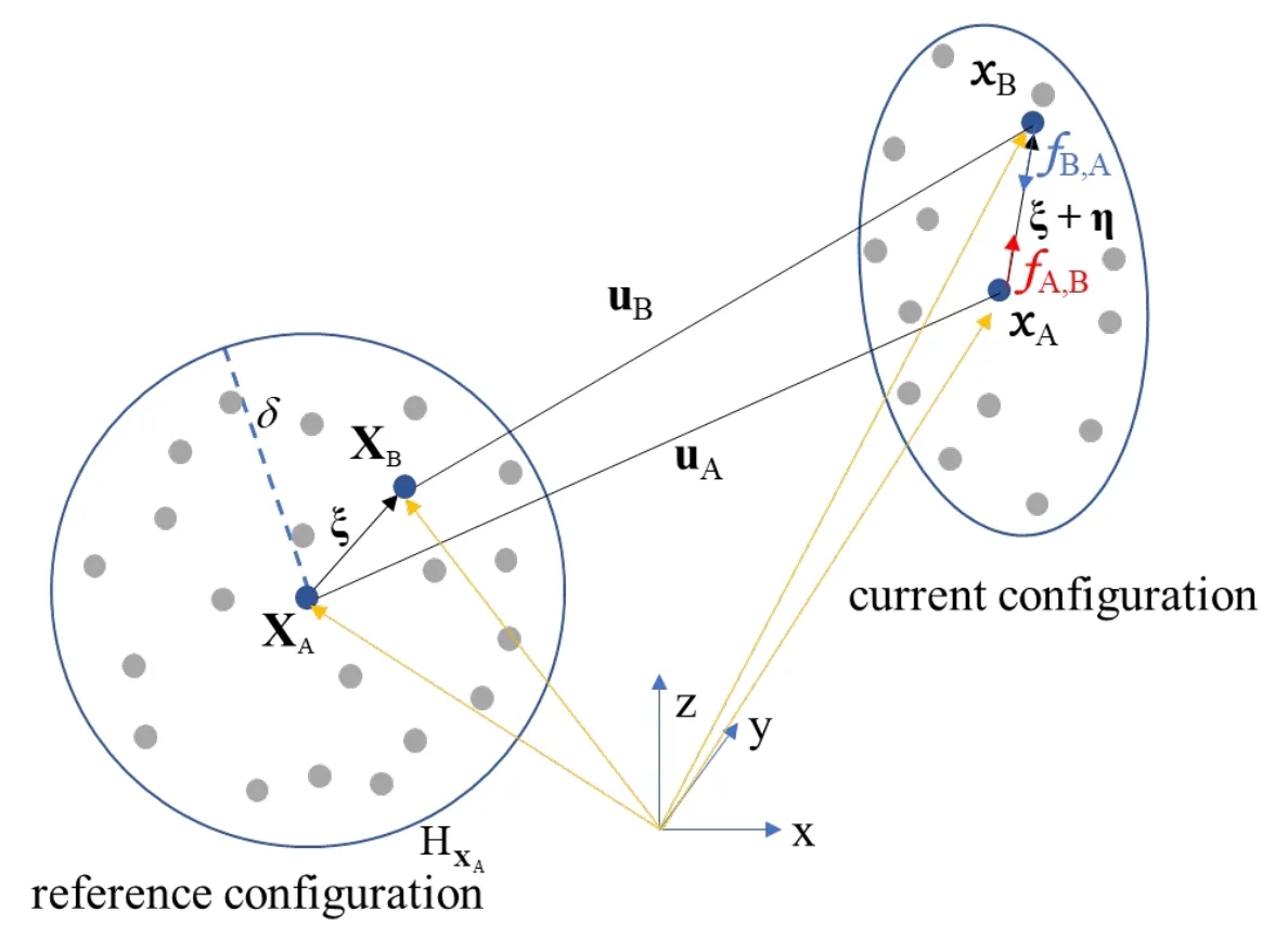
Figure 1:Deformation of PD particles in bond-based PD
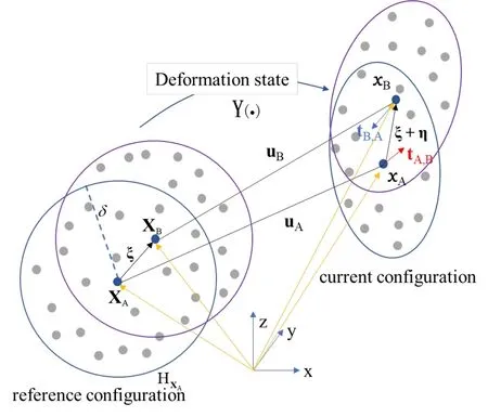
Figure 2:Deformation of PD particles in state-based PD
In the state-based PD theory,the second term in Eq.(2) is calculated from an integration:

whereA,Bt is called the force density vector as shown in Fig.2,which can be viewed as the force that particle xBexerts on particle xA,which are calculated using the formula:

where KAis the shape tensor of PD particle XA,which is defined in the reference configuration as


where SAis the second Piola-Krichhoff stress and FAis the deformation gradient.The stress SAcan be calculated based on a 3D constitutive material model,i.e.,

in which EAis the deformation of the particle calculated as

where FTis the transformation matrix of FAand I is the identity matrix.The key step in the state-based PD is the calculation of the deformation gradient FAused in Eqs.(7) and (9).According to the literatures [Silling,Epton,Weckner et al.(2007);Gerstle (2015)],FAcan be calculated by

where N is a second order tensor representing the shape of the deformed configuration:

where Y(ξAB) = xB- xA= ξAB+ηAB,which represents the deformation state.
2.2 The material constitutive models in OpenSees
The material constitutive in OpenSees can be described as:

where σ,ε and D are the stress tensor,the strain tensor and the tangent stiffness matrix at integration point of FE meshes,respectively.There are various material constitutive models in OpenSees.In this paper,two models are used in the demonstration examples,i.e.,a 3D multi-yield surface (MYS) model and a 3D cap plasticity model which are usually used for modeling the soil and concrete materials,respectively.The two material constitutive models are reviewed briefly in the subsections.
2.3 Multi-yield-surface (MYS) plasticity model
Multi-yield-surface (MYS) plasticity model is proposed by Iwan [Iwan (1967)],Mroz [Mroz (1967)] and Prevost [Prévost (1977)] for simulating metal and soil materials.It is further developed,enhanced and implemented into OpenSees by Elgamal and co-workers [Elgamal,Yang and Parra (2002);Yang and Elgamal (2002);Yang,Elgamal and Parra (2003)] for study of complicated soil behaviors.Compared with the classic J2 plasticity model which has only one yield surface,the MYS model has a number of similar yield surfaces to represent a better plastic behavior of the soil model under cyclic loading conditions.
2.3.1 The backbone curve and multiple yield surfaces
In geotechnical engineering,the octahedral shear stress strain behavior of soil material can be defined by a backbone curve which is usually determined by experiments,i.e.,

where G,τandγare the low strain shear modulus,the shear stress and the shear strain,respectively.The parameterγris a reference shear strain.In the context of MYS,the smooth hyperbolic backbone curve is replaced by a piecewise linear approximation (see Fig.3).Each line segment corresponds to one yield surface.
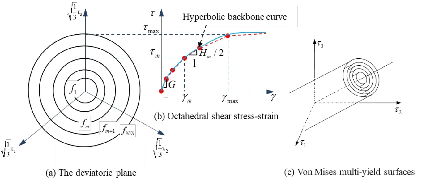
Figure 3:The yield surfaces of the MYS model
Each yield surface is defined in the deviatoric stress space as,

in which τ ,α and K are the deviatoric stress tensor,the back-stress tensor and the size of the yield surface,respectively,as shown in Fig.3(a).The subscript i denotes the ithyield surface,and NYS is the number of outermost yield surface.Fig.3(c) shows the yield surfaces at the initial loading time,which are concentric cylindrical surfaces in the deviatoric stress space.The outermost yield surface,i.e.,NYSf=0,is the failure surface which defines a geometrical boundary.
2.3.2 Flow rule and hardening law
An associative flow rule is defined in the deviatoric stress space [Gu,Conte,Elgamal et al.(2009)] as follows:

wheredεpis the plastic strain increment.Q represents the plastic flow direction normal to the yield surface.L=Q :dτ is the plastic loading function and the symbol 〈〉 represents the MacCauley’s brackets,i.e.,〈L〉= max(L,0).H' is a constant plastic shear modulus.A pure deviatoric kinematic hardening rule is employed to generate the Masing-type hysteretic cyclic response under arbitrary cyclic shear loading conditions [Elgamal,Yang,Parra et al.(2003);Gu,Conte,Yang et al.(2011)].The yield surfaces translate in stress space within the failure envelope [Hill (1998)] and there is no overlapping between any two yield surfaces.The details can be found in the literature [Gu,Conte,Elgamal et al.(2009)].
2.4 Cap plasticity model for concrete
Cap plasticity model is defined by a non-smooth,convex surface which consists of three yield surfaces,i.e.,a failure envelope,a tensile cut-off region and a hardening cap.It is proposed by FL DiMaggio and IS Sandler in 1971 [DiMaggio and Sandler (1971);Sandler,Dimaggio and Baladi (1976);Sandler and Rubin (1979)] and further developed by Hofstetter [Hofstetter,Simo and Taylor (1993)].
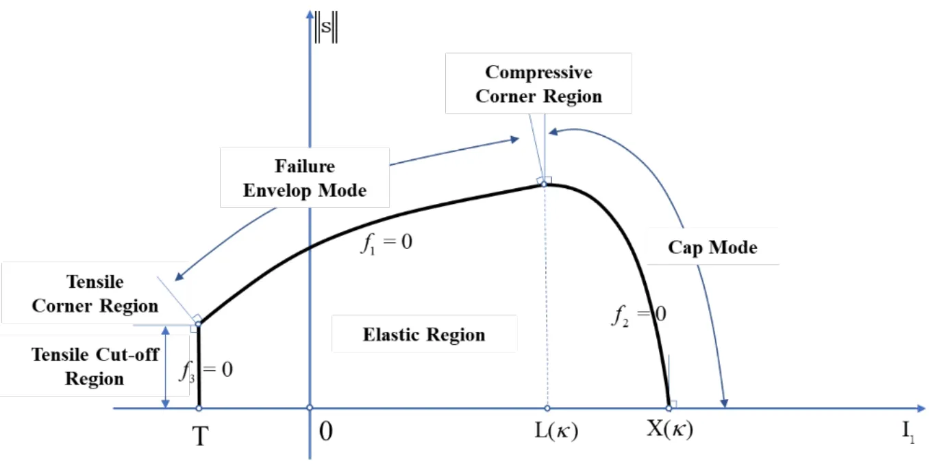
Figure 4:The Cap plasticity model
2.4.1 The yield surfaces
Three yield surfaces are used to define the Cap plasticity model.As shown in Fig.4,1fis the failure envelope which is defined as

where

s and I1are the deviatoric and volumetric stress,respectively.is the norm of the deviatoric stress tensor s .α,β,λandθare material parameters for the failure envelop.In the cap region,

whereκis a hardening parameter andIn the tensile cut-off region,f3is defined as

where T is the maximum hydrostatic tension.
2.4.2 Flow rule and the hardening law:
The flow rule of the model and the consistency condition (i.e.,the Kuhn-Tucker condition) are defined as


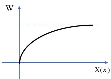
Figure 5:The relationship between W and X(κ)
2.5 The integration method
The integration of PD program and OpenSees is achieved based on the Client-Server software technique.The flowchart of PD,OpenSees and their interaction are illustrated in Fig.6.
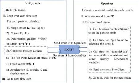
Figure 6:The flow chart of the integration method
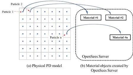
Figure 7:The particles in PD model and corresponding material objects in OpenSees memory
As shown in Fig.6,the procedure of the PD-OpenSees software platform is as follows:
Step 1:Build the PD model using PD program and create an OpenSees server.
Step 2:For each particle in PD model,build a corresponding material object in OpenSees server side.A communication channel between PD and OpenSees is established using Tcl socket command.As shown in Fig.6,the material objects keep in the memory and wait for commands from the PD.
Step 3:In the PD program,for each time step,the shape tensor K,the second order tensor N,the deformation gradient F and the strain tensor E are calculated for each particle using the Eqs.(6),(11),(10) and (9),respectively.
Step 4:PD sends the strain E to OpenSees through the socket.
Step 5:OpenSees receives the strain,calls its material objects to calculate the stress using Eq.(8).The strain,stress and other variables are committed for the calculation of the next time step.
Step 6:OpenSees sends the stress back to PD program,then waits in memory for the next commands (e.g.,strain) from PD program.
Step 7:PD program receives the stress,calculates the PK-I stress and the force vector state T using Eqs.(7) and (5),respectively.
Step 8:PD program calculates the acceleration of the PD particle using Eq.(1),updates the velocity and displacement,and then goes to Step 3 for the next time step.
The above steps from 1 to 8 are repeatedly performed until the last analysis step is done.
3 Application examples
Two examples are presented herein to verify the integrated PD-OpenSees platform.The first example is a plate with a pre-crack subject to horizontal tension force,and the material is simulated using the MYS model.The second one is a block with a rectangular hole subject to uniaxial loading condition simulated using the cap plasticity model.
3.1 Plate with a pre-crack
The first example presented herein is a plate with a pre-crack subject to horizonal tension force.As shown in Fig.8,the PD model is discretized into 8910 particles with 2 layers.The length and width of the plate are both 1.89 m,the grid sizedxis 0.03 m,the time stepdtis 0.000004 s,the critical stretchs0is 0.05 and the horizon radiusδis 3.015 times the grid size (i.e.,0.09045 m).The material is simulated using the MYS model with parameters shown in Tab.1.The computation results are analyzed and compared with the one using linear elastic material model whose parameters are also shown in Tab.1.The plate is subject to tension forces at two boundaries,as shown in Fig.8.The total load steps are 23000.An octahedral shear stress defining the yield surfaces in Eq.(15) is used to study the stress responses of the model,which is:

whereσxx,σyy,σzz,σxy,σxzandσyzare the components of the stress σ calculated using Eq.(12).
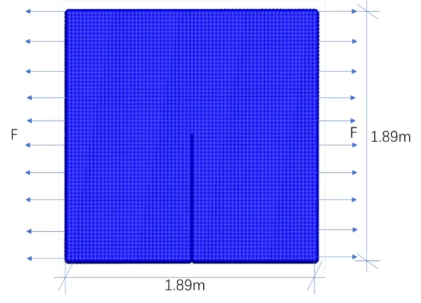
Figure 8:PD model of the plate with a pre-crack
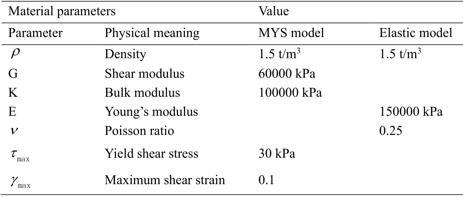
Table 1:Material parameters of MYS model and elastic model

Figure 9:The load history,deformation and the contour of octahedral shear stress at different time steps using the MYS model
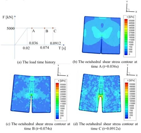
Figure 10:The load history,deformation and the contour of octahedral shear stress at different time steps using elastic model
Fig.9 shows the load time history,the deformation and the contour of octahedral shear stress at three representative time steps using the MYS model.In Fig.9(a),the force increases linearly from zero until it reaches 750 kN at 0.02 second and remains unchanged after then.The stress and deformation of the plate at three representative time steps (i.e.,A,B and C corresponding to 0.036 s,0.048 s and 0.0792 s respectively) are shown in Figs.9(b)-9(d).For comparison purpose,the load time history,the deformation and the contour of octahedral shear stress at three representative time steps (i.e.,A,B and C corresponding to 0.036 s,0.074 s and 0.0912 s respectively) using the elastic model are shown in Figs.10(a)-10(d),where the load increases linearly until reaches 5000 kN at 0.02 second and keeps unchanged afterwards.
From Fig.9 and Fig.10,it is observed that when using MYS model,the stress at the crack tip region grows fast along approximate 45 degrees to the pre-crack,then grows slower after yielding.However,the crack does not obviously extend or propagate along any direction but concentrates in a small region around the crack tip as shown in Fig.9(d).While using elastic model,the stress increases fast at the crack tip at beginning,similarly with the use of MYS models in Fig.9,until failure occurs.However,the force at failure is much larger than that for MYS case (i.e.,5000 kN for elastic case instead of 750 kN for MYS case) due to the much larger tension resisting capacity of the elastic material.After then the crack propagates along the pre-crack direction and finally penetrates the plate as shown in Fig.10(c) and Fig.10(d).
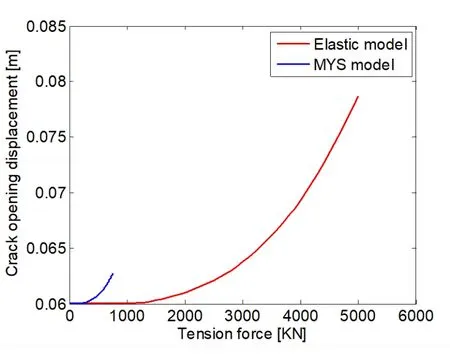
Figure 11:Comparison of the crack opening displacement with increasing tension force between MYS model and elastic model
Fig.11 compares the crack opening displacement with increasing tension force between MYSvs.elastic models for the first 5000 loading steps.The original crack opening displacements are 0.06 m for both cases.It is observed that the crack opening begins to propagate when the tension force is 126 kN for MYS model,which is much smaller than the tension force of 1400 kN for elastic model.When the tension force is 750 kN,the crack opening displacement for MYS model reaches 0.0628 m,while that for elastic model remains unchanged,i.e.,0.06 m.This is also because that the elastic material has much larger tension resisting capacity than plastic material.
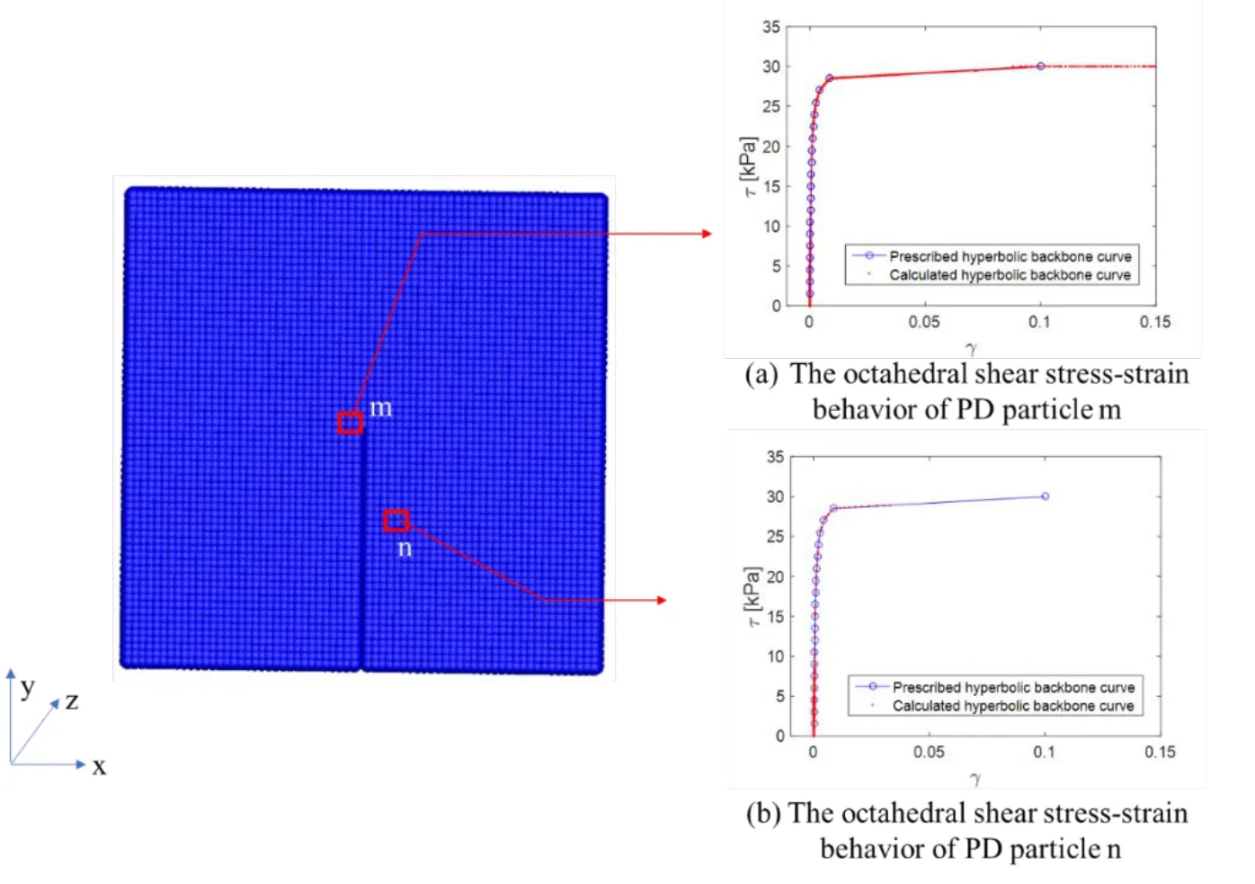
Figure 12:The octahedral shear stress-strain behavior of the PD particles when using MYS model
The octahedral shear stress-strain behaviors of two representative PD particles (i.e.,PD particles m and n) are presented in Fig.12(a) and Fig.12(b) respectively.From these figures,it is observed that the calculated octahedral shear stress at the two particles increase along the prescribed hyperbolic backbone curve,which verifies the integrated PD-OpenSees platform presented herein.
3.2 A concrete block with a rectangular hole subject to compressive force
The second application is a concrete block with a rectangular hole in the center subject to compressive force.As shown in Fig.13,the length,width and height of the block are all 0.45m,the side length of the hole inside the block is 0.15 m.The PD model is discretized into 3270 particles with the grid sizedx(i.e.,the initial particle distance) 0.03 m as shown in Fig.13.The time stepdtis 0.000004 s,the critical stretchs0is 0.02,and the horizon radiusδis 0.09045 m.The compressive force is applied at both the top and bottom of the block,and the load time history is shown in Fig.14(a).The Cap plasticity model is applied in this example and the material parameters are shown in Tab.2.The total load steps are 2000.A deviatoric stress used to define the yield surfaces of Cap plasticity model in Eq.(17) is used to study the stress contour of the model,whose norm is defined as:

where I1=σxx+σyy+σzzis the first stress invariants,σxx,σyy,σzz,σxy,σxzandσyzare the components of the stress σ.
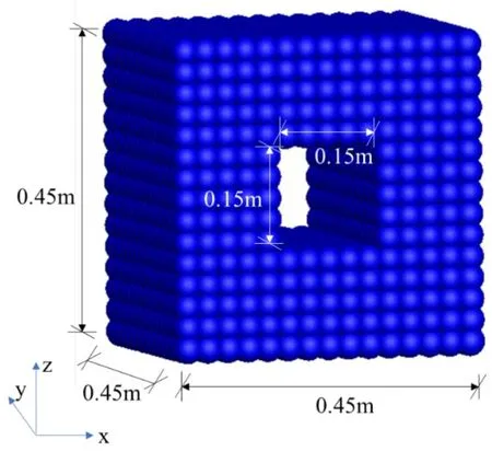
Figure 13:The PD model of a concrete block
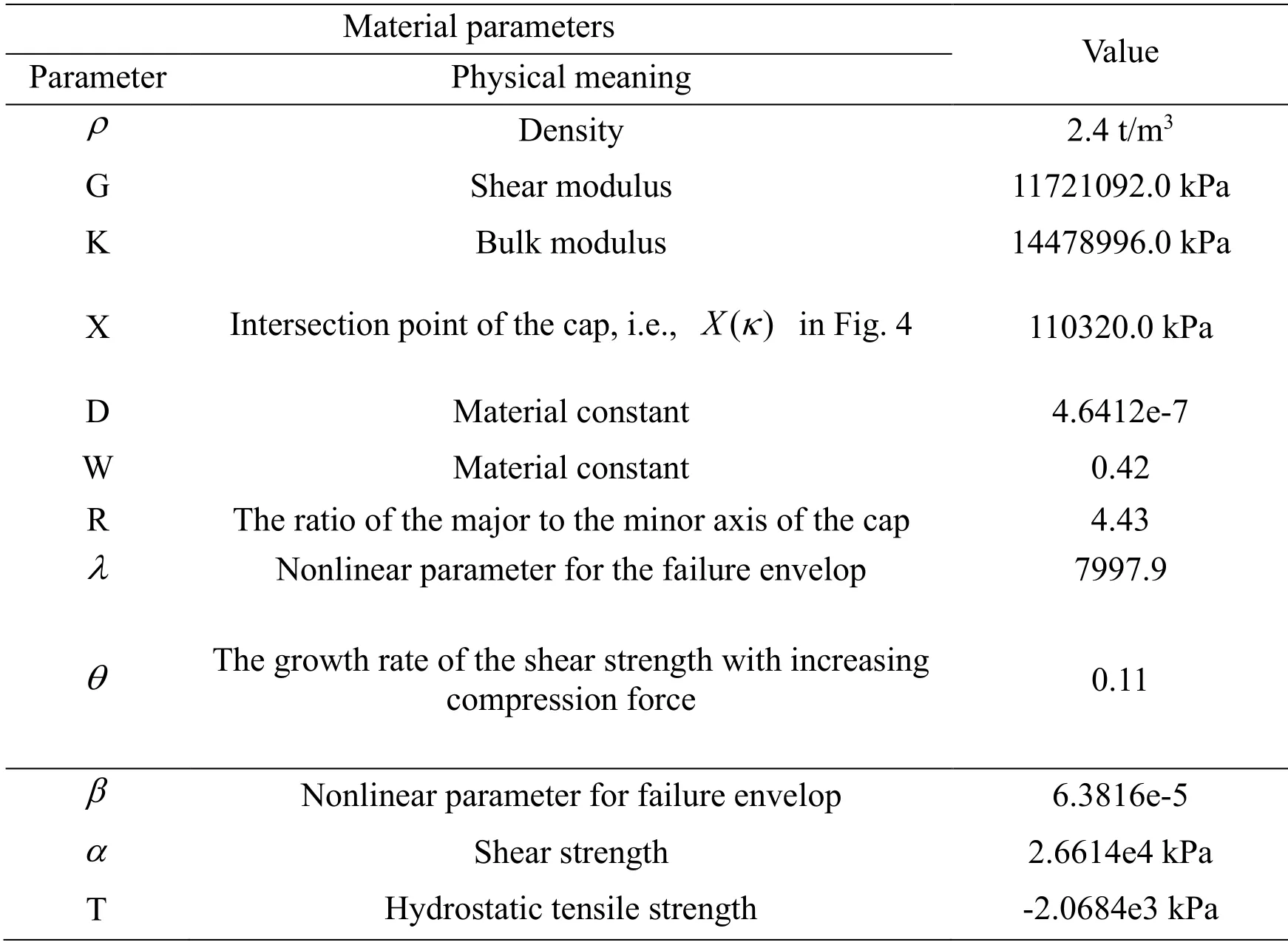
Table 2:Material parameters of the Cap plasticity model
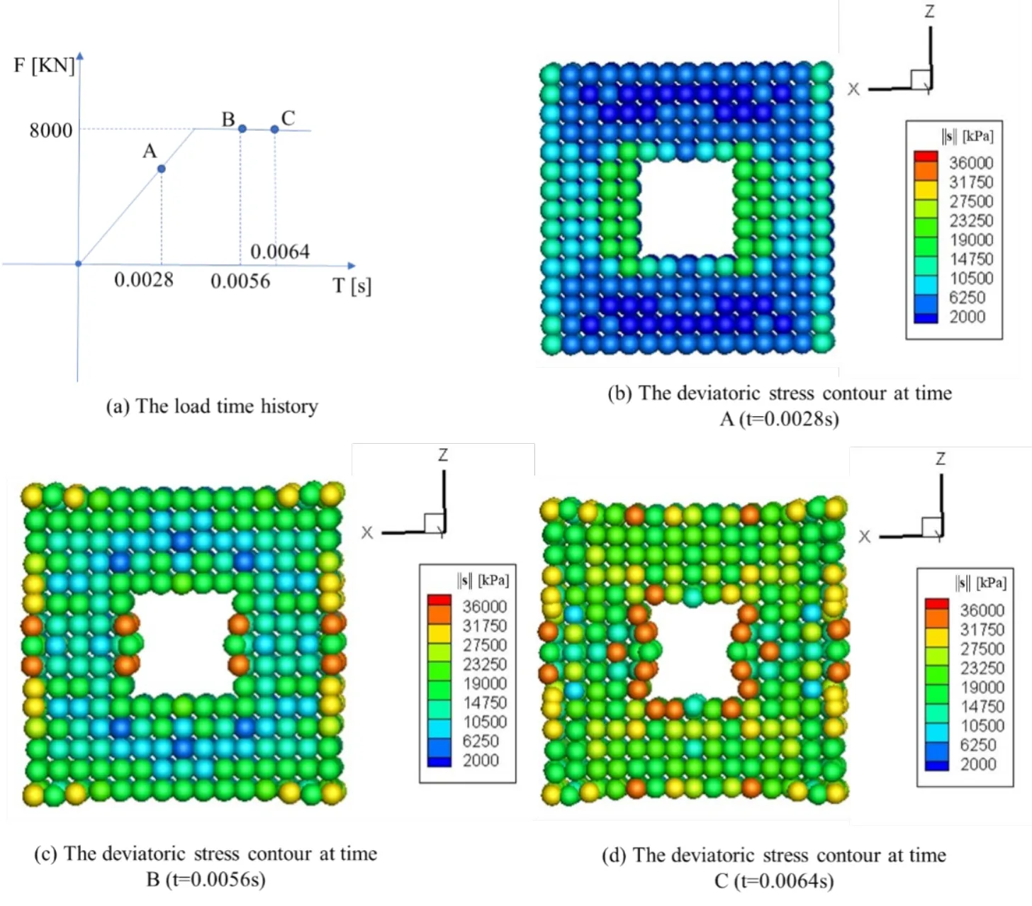
Figure 14:The load history,deformation and the contour of deviatoric stress at different time steps using Cap plasticity model
Fig.14 shows the load time history,deformation and the contour of deviatoric stress at three different time steps ((i.e.,A,B and C corresponding to 0.0028 s,0.0056 s and 0.0064 s respectively as shown in Fig.14(a)).The stress increases fast at the left and right sides of the hole as shown in Fig.14(b).After then the brick tends to be compressed in z direction while expanded in x direction due to the Poisson effect (see Figs.14(c)-14(d)).Vertical cracking occurs at the left and right side of the rectangular hole and grows wider with increasing loads.
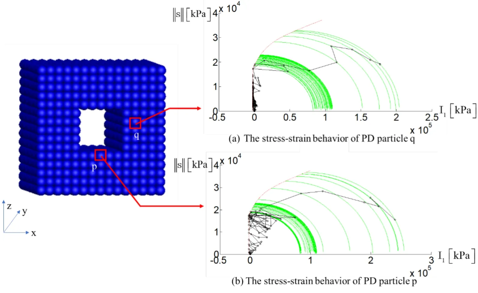
Figure 15:The stress-strain behavior of two representative PD particles
Fig.15 shows the stress-strain behaviors of two representative PD particles p and q.At the beginning of the loading steps,the stress point moves inside the yield functions (i.e.,in the elastic region).With increasing loading,the stress point reaches the yield surface of the tensile cut-off region (i.e.,f3= 0 in Fig.4) at first,and then the yield surface of the failure envelop (i.e.,f1= 0).Finally,the stress point reaches the yield surface of the cap ((i.e.,f2= 0),which expands the cap outward (i.e.,move towards right in the Fig.15(a) and Fig.15(b)) with the hardening parameterκenlarged.It is observed that the results follow the definition of the yield surfaces and hardening law of the Cap plasticity model in Section 2.4,which verifies the integrated PD-OpenSees platform presented herein.
4 Conclusion
Peridynamics (PD) is a powerful method to solve the discontinuous problems,which is commonly encountered in civil engineering.However,it may take a lot of effort to implement the various material constitutive models into PD program.OpenSees,an open source finite element software,has been widely used in the civil engineering which has versatile material libraries.This paper integrates PD with OpenSees by using a Client-Server (CS) software integration technique.By combining the state-based PD program with 3D plastic constitutive models,the integrated method is capable to solve the complex generation and propagation processes of cracks of elastoplastic material efficiently.Two applications are presented to verify the integrated PD-OpenSees software platform.The first one is a plate with a pre-crack simulated using the MYS model subject to horizontal boundary tension forces.It is observed that the stress at the crack tip region grows fast along approximate 45 degrees to the pre-crack,then grows slower after yielding occurs.However,the crack does not obviously extend or propagate along any direction but concentrates in a small region around the crack tip.This is different from the results using elastic model,in which the crack propagates along the pre-crack direction and finally penetrates the entire plate.The second one is a concrete block with a rectangular hole simulated using the Cap plasticity model subject to vertical compression force.Results show that the brick tends to be compressed in z direction while expanded in x direction with increasing loads.In both application examples,the stress-strain behaviors of representative PD particles follow the definition of the plasticity models in the sense of yield surfaces,flow rule and hardening law,which indicates that the integrated PDOpenSees software platform presented herein is potentially capable to solve a wide range of problems in civil engineering.
Acknowledgement:The authors acknowledge the financial supports from the National Key Research and Development Program of China with Grant No.2016YFC0701106 and the National Natural Science Foundation of China with Grant Nos.51261120376 and 51578473.The authors would like to thank Arjen Markus for his work on the ftcl module used in the Fortran program.
 Computer Modeling In Engineering&Sciences2019年9期
- Computer Modeling In Engineering&Sciences的其它文章
- Coupling of Peridynamics and Numerical Substructure Method for Modeling Structures with Local Discontinuities
- The Behavior of Rectangular and Circular Reinforced Concrete Columns Under Biaxial Multiple Excitation
- Real-Time Hybrid Simulation of Seismically Isolated Structures with Full-Scale Bearings and Large Computational Models
- Structural Finite Element Software Coupling Using Adapter Elements
- Experiment and Simulation for Controlling Propagation Direction of Hydrofracture By Multi-Boreholes Hydraulic Fracturing
- Determination of Working Pressure for Airport Runway Rubber Mark Cleaning Vehicle Based on Numeric Simulation
