Simulation Analysis on Quasistatic Characteristics of Multistage Face Gears with Double Crown Surface
Xingbin Chen,Qingchun Hu, ,Zhongyang Xu,Yao Ding,Qianli Mai and Chune Zhu
Abstract: The multistage face gears are the core component of the planetary gear train,which is symmetrically meshed by multiple single-stage face gear and multiple cylindrical gears.However,it is difficult to synchronize the contact between face gears and cylindrical gear due to the tooth number differences.Thus,the interference problems between two stages and big stress concentration are obvious.The crown surface configuration technology and structure design were introduced to optimize the meshing condition.To improve the double crown design feasibility and meshing stability,it is necessary to establish a reasonable multistage face gears pair simulation model to evaluate various influence factors on the contact condition and quasi-static characteristics of multistage face gears structure.The relevant scatter plots are fitted by comparing the contact results with different crown quantities and friction coefficients to intuitively obtain the variation regularity of maximum deformation,maximum strain,maximum stress and maximum strain energy.The natural frequency and mode coefficient are also determined by modal analysis under these two conditions.All the above mentioned studies verified the contact conjugate properties of double crown surface configuration were suitable.The results can provide a foundation for structure optimization and transmission reliability of multistage face gears.
Keywords:Multistage face gears,quasi-static contact characteristics,modal characteristics,double crown surface,simulation analysis.
1 Introduction
Face gears with double crown structure can minimize the meshing interference and control the local conjugacy of contact region.However,it is still very sensitive to the design,processing,installation error,and the natural characteristics of gear will generate dynamic load and vibration during the transmission [Li,Ye,Zhang et al.(2016)].These internal excitations easily generate complex alternating forces with external excitations,causing sever vibration and distortion,and directly affecting the safety and stability of transmission system [Inoue and Kurokawa (2017)].Litvin et al.studied the application of asymmetric profiles and double-crowned pinion of face-gear drives for application in transmissions.They covered computerized design,simulation of meshing and contact,and stress analysis by finite element method [Litvin,Fuentes and Howkins (2001)].Liu et al.[Liu,Shu,Kanazawa et al.(2018)] developed a modeling technique based on Arbitrary Lagrangian Eulerian (ALE) formulation to reduce the DOF while providing accurate gear meshing contact simulation.Litvin et al.[Litvin,Fuentes,Zanzi et al.(2002)] improved the conjugate conditions in point contact using the tooth number difference between two gears.Zhou et al.[Zhou,Chen,Gui et al.(2018)] proposed a practical nonlinear multipoint meshing model for the determination of face load factor.The static equilibrium condition of entire spur gear system was obtained through iterative calculation,and both the load distribution and face load factor were obtained.Li et al.[Li,Fan and Zhu (2018)] carried out a modal analysis on face gear transmission models,and obtained the trend of natural and vibration mode of face gear.The results optimized the vibration characteristics of transmission system and improved the weakness.Shen et al.[Shen,Liu,Li et al.(2018)] evaluated a new approach to apply the double-crowned helical pinion of a face gear drive.The computer simulation results showed that the bearing contact is not sensitive to the errors of misalignment.Zhang et al.[Zhang,Qi,Gou et al.(2017)] completed the modal analysis,static analysis and dynamic contact transient analysis for involute helical gears using ANSYS.Zhang et al.[Zhang,Qi,Gou et al.(2017)] constructed a finite element model of the modified gear under load condition and analyzed the influence of tooth profile error,tooth profile meshing dislocation,contact deformation of tooth profile surface and load on transmission error,which was validated by two cases:benchmark FEM from Eritenel and Parker,model from Andersson and Vedmar [Wang and Zhang (2017)].These studies provide a good basis.Multistage face gears with reconstructed double crown surface were evaluated based on theoretical analysis and numerical simulation,to obtain the size and distribution of contact deformation and determine the coefficient of natural frequency and vibration mode,thus reducing the transmission discontinuity and movement instability caused by contact deformation and resonance of multistage face gears transmission mechanism.
2 Structure modeling of multistage face gears with double crown configuration
Double crown configuration is used to improve the meshing contact area of tooth surface between cylindrical gear and face gear,which should be close to the central tooth as far as possible [Tran,Hsu and Tsay (2015)].It is also used to extend the contact line to avoid the phenomenon such as stress concentration,partial loading and interference in face gears.
2.1 Tooth profile crown surface configuration of face gear
The tooth profile crown is formed through a parabolic reconstruction,which extends from the tooth addendum direction to tooth root direction [He,Lin,Luo et al.(2016)].
By taking a profile projection of face gear as the study object,as shown in Fig.1,the tooth profile crown is composed of an approximately parabola,assuming that the centralo′ of tooth thicknessSis a parabolic virtual center,lpis the radius,u0is the vertex position parameter of tooth profile parabola,u′fis the surface parameter in the direction of tooth profile,is the profile parabola deformation,ε′ is the profile parabola coefficient.The parabolic deformation in the arbitrary profile of face gear can be expressed as follows:

By introducing the projection of generating a gear coordinate system,the parabolic crown surface of any tooth profile can be expressed as follows [Tsay and Fong (2007)]:

The unit vector can be expressed as follows:

In Eq.(3),u′fis the tooth surface parameter in the tooth profile direction of generating gear,andφs′iis a tooth surface parameter along the length.
According to the envelope principle,the surface of face gear tooth profile crown can be expressed as follows:

The unit normal vector of face gear tooth profile crown can be expressed as follows:

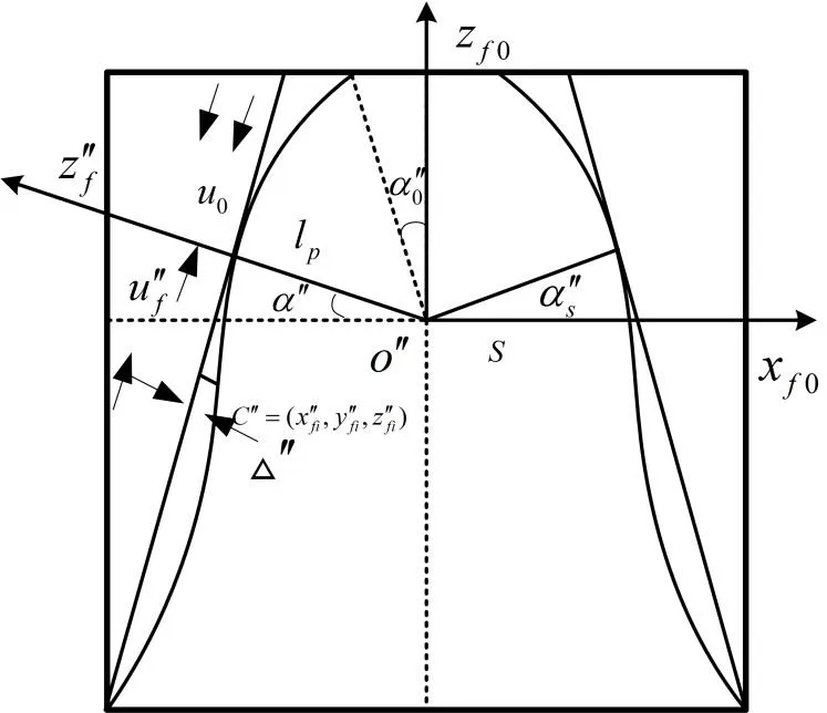
Figure1:Projection about tooth profile crown
2.2 Tooth orientation crown surface configuration of face gear
The tooth orientation crown is a configuration that gradually decreasing the thickness of the tooth thickness towards both directions of gear tooth,as shown in Fig.2.
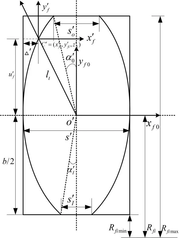
Figure 2:Projection about longitudinal tooth crown
By selecting one orientation projection of face gear as the study object,and assuming that the crown is composed of parabolic and mirror curves,with that the centralo" of tooth thicknessis parabolic virtual center,ltis the radius,is the surface parameter in the direction of tooth profile.is the profile parabola deformation,ε′ is profile parabola coefficient.
The parabolic deformation in the arbitrary orientation of face gear can be expressed as follows:

According to the tooth orientation coordinate system of face gear,the parabola silhouette in tooth orientation direction is the transverse silhouette of generating gear,that is= 0.
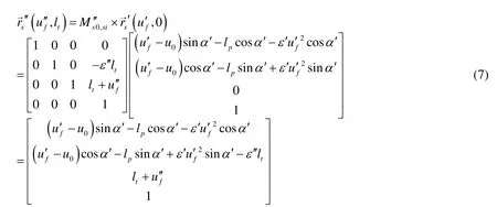
The unit vector can be expressed as follows:

The double crown surface of face gear can be expressed as follows:
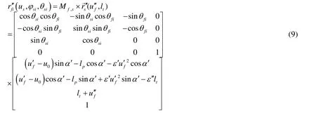
That is:

The unit vector of double crown surface of face gear can be expressed as follows:

It is difficult to construct the model accurately using a single 3D drawing software (e.g.Siemens NX 10.0,“UG” for short) because of the complexion double crown surface configuration of face gear.By calculating the point coordinates of tooth surface by Matrix Laboratory (Matlab) software,the complete surface structure can be modeled by UG software.The parameters of double crown surface model are shown in Tab.1.The results of configurations are shown in Figs.3 and 4.
According to our experience,the range of crown quantity for the gears should be taken as10 μm<ε<40 μmwith general precision.Furthermore,it should be increased by5 μmto compensate the manufacturing error.However,the crown quantity should be reduced appropriately under the conditions of high speed or high accuracy.The range should be taken as10 μm<ε<25 μm,and5 μmmanufacturing error should be included.Thus,the crowned teeth were reconstructed according to crown coefficients,as shown in Fig.5.
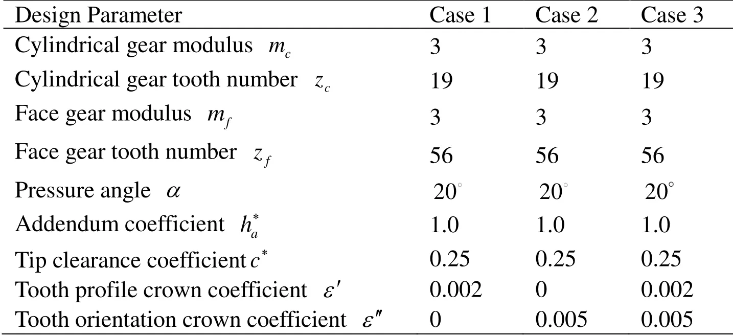
Table 1:Design parameters of double crown configuration tooth surface of face gear pair
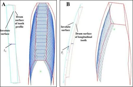
Figure 3:A:crown configuration of tooth profile surface;B:crown configuration of longitudinal tooth surface
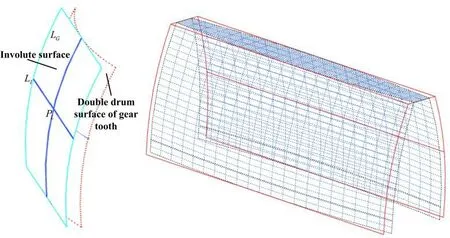
Figure 4:Double crown configuration of gear tooth surface

Figure 5:A:coordinate sketch of face gear;B:double crown reconstruction suture;C:comparison before and after the reconstruction of Double crown
3 Quasi-static contact analysis of multistage face gears pairs
The core components of multispeed variable transmission mechanism are extracted for quasi-static contact characteristics analysis,which are studied for different crown quantities and friction coefficients.
3.1 Structure assembly modeling of multistage face gears
According to the layout of entire transmission,the structural parameters of model are as follows:the module of cylindrical gears (four symmetrical arrangement) ismc= 3,the teeth number iszc= 19,the pressure angle isα= 20,the addendum coefficient isha*= 1.0,and the tip clearance coefficient isc*= 0.25.Moreover,the module of face gears are allmf= 3,the teeth numbers ( the number of teeth per level must be in multiples of 4) arezfa= 56,zfb= 68,zfc= 80,the pressure angles areα= 20,the addendum coefficients areha*= 1.0,and the tip clearance coefficients arec*= 0.25.The assembly structure is shown in Fig.6.
By comparing with the multistage gear system or single-stage face gear system,the characteristics of the assembly structure indicate that the multistage face gears system has more advantages,such as a flexible space layout,a simple component structure,easily variable transmission ratio,flexibly extending the speed ratio range,significant component interchangeability,a strong symmetrical assembly structure,a simple transmission mechanism,easily controlled strategy matching,and a convenient speed regulating actuator.Thus,the multistage face gears system can be widely used under the conditions of high speed,overloading and micro precision.The system composed of cylindrical gears and multistage face gears can not only simplify the structure and save space,but also set the series of face gear according to the transmission ratio locale.
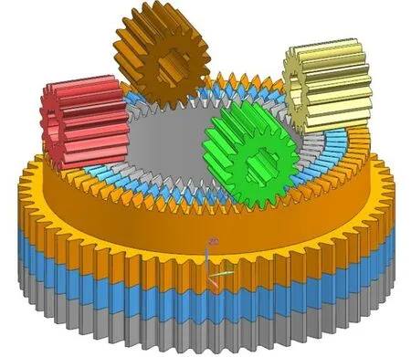
Figure 6:Multistage face gears pair assembly modeling
3.2 Finite element modeling about quasi-static contact
The established gear assembly model is added to ANSYS Workbench for analysis.The selected material is C45 (Elastic modulusE= 2.09 ×e+ 1 1Pa,Poisson ratioν= 0.269,Densityρ= 7890kg/m3).The grid is divided using Automatic method with an element of 2 mm.The displacement constraint in the bottom of the face gear along the Z direction is set as 0.The rotational DOF (degree of freedom) of face gear is set as Z axis,and the other DOF are fixed.The rotational DOF of cylindrical gears is set as X axis,and the other DOF are fixed.A rotation torque with 100,000N mm⋅ is added to the shaft hole of the cylindrical gear,and the direction is clockwise,corresponding to the direction of defined contact.
By comparing with the analysis results shown in Fig.7 and Fig.8,the following conclusions can be drawn:
(1) The elastic deformation caused by a large load makes the point contact of tooth surface as surface contact.In theory,the contact area should be oval.However,because of the errors of finite element model and algorithm,the contact area in figures is an approximate ellipse.
(2) When the load of face gear is fixed,the contact stress of each level gear changes with the switching of the face gears.This is because the contact pressure in different face gears’ teeth decreases with the increase in radius of face gears.
(3) The contact area shifts toward the center of tooth as the transmission ratio increases during the rotation.
(4) The maximum deformation is 0.10543 mm,which satisfies the maximum deformation requirement of gear pair.

Figure 7:A:contact area analysis of cylindrical gear;B:contact area analysis of face gears
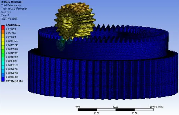
Figure 8:Deformation analysis under static load contact
3.3 Contact characteristic analysis of different crown quantities under quasistatic conditions
In the previous study,the gear tooth type has been reconfigured with crown shape,the tooth profile was assumed to be Δ ′,and the tooth orientation was,as shown in Fig.9.According to the selection principle for the crown quantity of high speed and heavy load gears [Han,Zhu,Xia et al.(2018)],and considering the machining error,the crown quantity was selected within the range of10 μm<ε<30 μm,to analyze the deformation,strain,and stress of face gears with different crowns.To simplify the research,it was assumed to select the same crown size of tooth profile and tooth orientation for study,Δ′ == 0,0.01,0.012,0.015,0.018,0.02,0.022,0.025,0.028,and 0.03,as shown in Tab.2.
According to the data mentioned above,10 polynomial fitting equations were written and run in MATLAB to obtain each order constant of polynomial and the scatter plots of each crown.The coefficients from the highest (10 times) to the lowest (0) can be determined,and the terms that close to 0 are omitted.
(1) Ten polynomial fitting equations and the scatter plots of maximum deformation amount of different crown are shown in Fig.10A.

(2) Ten polynomial fitting equations and the scatter plots of maximum strain amount of different crowns are shown in Fig.10B.

(3) Ten polynomial fitting equations and the scatter plots of maximum stress amount of different crowns are shown in Fig.10C.

(4) Ten polynomial fitting equations and the scatter plots of strain energy amount of different crowns are shown in Fig.10D.

From Tab.1 and Fig.10,for each crown configuration of multistage face gears structure,the maximum deformation,maximum strain,stress,and strain energy decreased with the increase in crown quantity.In contrast,the maximum deformation is approximately linearly decreased with the increase in crown quantity.The maximum strain gradually decreased under the crown volume of the interval (0-0.01),and rapidly decreased under the interval (0.01-0.02).The decreasing trend of maximum stress is almost the same as that of maximum strain.Moreover,the decreasing trend of strain energy is almost the same as the maximum deformation.However,owing to the large ratio of crown quantity interval and gear tooth size,the contact characteristics are influenced by factors such as structure design error,assembly error,and boundary conditions.Furthermore,the small error of these factors can also compensate the change in the contact characteristics caused by different values of crown quantity.Therefore,more factors should be considered for the study of contact characteristics of multistage face gears with different crown configurations,but the trend is stable under the crown condition.
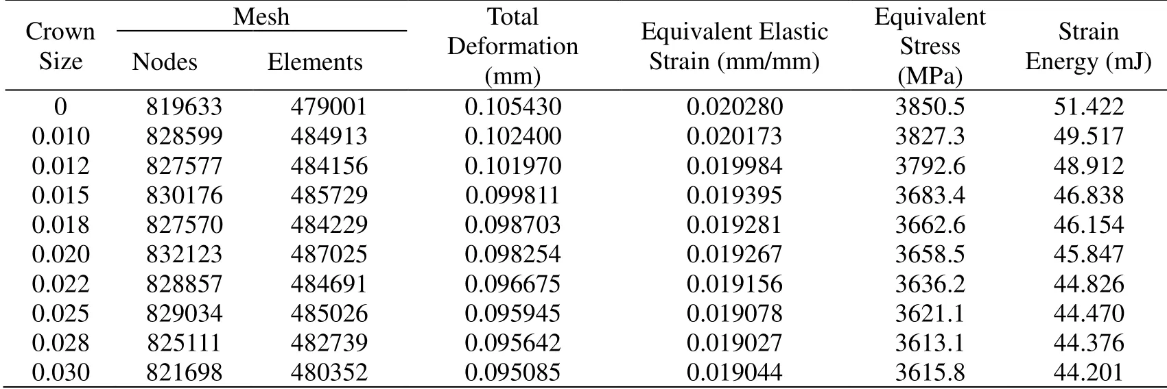
Table 2:Contact characteristics of different crown quantities
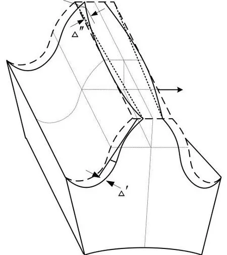
Figure 9:Schematic diagram of double crown configuration
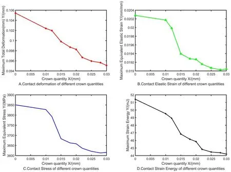
Figure 10:A:deformation scatter diagram of different crown quantities;B:maximum Strain scatter diagram of different crown quantities;C:maximum Stress scatter diagram of different crown quantities;D:strain Energy scatter diagram of different crown quantities
3.4 Contact characteristic analysis of different tooth surface friction coefficients under quasistatic conditions
According to the analysis results of friction coefficient and meshing efficiency of multistage face gears,it was assumed to select the friction coefficient for quasi-static contact analysis:μ=0,0.01,0.015,0.02,0.03,0.1,0.5,1,and 2,as shown in Tab.3.
According to the data shown above,10 polynomial fitting equations were also written and run by MATLAB to obtain each order constant of polynomial and the scatter plots of each friction coefficient,as shown in Fig.11.
(1) Ten polynomial fitting equations and the scatter plots of maximum deformation amount of different friction coefficients are shown in Fig.11A.

(2) Ten polynomial fitting equations and the scatter plots of maximum strain amount of different friction coefficients are shown in Fig.11B.

(3) Ten polynomial fitting equations and the scatter plots of maximum stress amount of different friction coefficients are shown in Fig.11C.

(4) Ten polynomial fitting equations and the scatter plots of strain energy amount of different friction coefficient are shown in Fig.11D.

From Tab.3 and Fig.11,there are different trends for maximum deformation,maximum strain,maximum stress,and strain energy of multistage face gears structure under the conditions of different tooth surfaces friction coefficients.The maximum deformation obviously decreases under the friction coefficient of the interval (0-0.5),and gradually decreases under the interval (0.5-2).The maximum strain obviously decreases under the friction coefficient of the interval (0-0.5),and linearly increases under the interval (0.5-2).The decreasing trend of maximum stress is almost the same as that of maximum strain,which obviously decreases under the friction coefficient of interval (0-0.5),and becomes stable under the interval (0.5-1),but linearly increases after slightly flattening under the interval (1-2).The strain energy increases like a parabola,which increases obviously under the interval (0-0.5),and increases gently under the interval (0.5-2).In fact,the change in tooth surface contact friction coefficient depends on various factors such as tooth surface material,tooth shape,load,surface fineness,working temperature,and lubrication state.If the friction coefficient is too large,the friction stress will increase,easily leading to gear premature wear,decreasing in transmission efficiency,rapid temperature rising,or even failure.Therefore,some appropriate measures should be taken to control the friction coefficient of gear tooth surfaces.
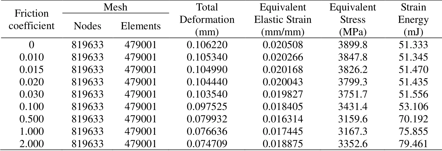
Table 3:Contact characteristics of different friction coefficients
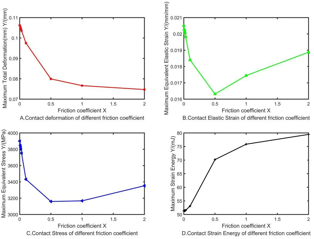
Figure 11:A:deformation scatter diagram of different friction coefficients;B:maximum strain scatter diagram of different friction coefficients;C:maximum stress scatter diagram of different friction coefficients;D:strain energy scatter diagram of different friction coefficients
4 Modal characteristics analysis
The settings of material properties and contact definitions are consistent with the static contact analysis.After the automatic dividing grid,the Node number is 819633,and the Elements number is 479001,defining of boundary condition constraint,solution,and then post-processing of results.The modal is the inherent property of system,independent of external load,therefor,no load is required.The ‘Iterative’ solution method is selected in the Iterative solver to extract the first six vibration modes and natural frequency of models,as shown in Fig.12 and Tab.4.
From Tab.4 and Fig.12,it shows that the main distribution range of first sixth order natural frequency for the face gears transmission models are between 3239.9~12193 Hz.According to the analysis results,when the working frequency of face gears transmission is close to a certain vibration mode,some design measures should be taken to avoid damage in the corresponding parts.That is to prevent the occurrence of resonance phenomena during running,which will lead to machine failure and vibration noise,even severely damaging the system.
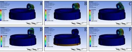
Figure 12:A:first-order modal;B:second-order modal;C:third-order modal;D:fourth-order modal;E:fifth-order modal;F:sixth-order modal

Table 4:Natural frequency of multistage face gear drive
4.1 Modal characteristic analysis of different crown quantities
According to the selection principle of crown quantity of high-speed gears and considering the machining error,the crown quantity is selected within the range of10 μm<ε<30 μmto analyze the magnitude of first six order natural frequency and the corresponding vibration mode of system,as shown in Tab.5.
From Tab.5,the natural frequency of each crown in the gear increases with the order.For the same order gears with different crown quantities,the natural frequencies also have a certain trend.The 10 polynomial fitting equations were written and run by MATLAB to obtain the constants of each order polynomial and the scatter plots of each crown,as shown in Fig.13.
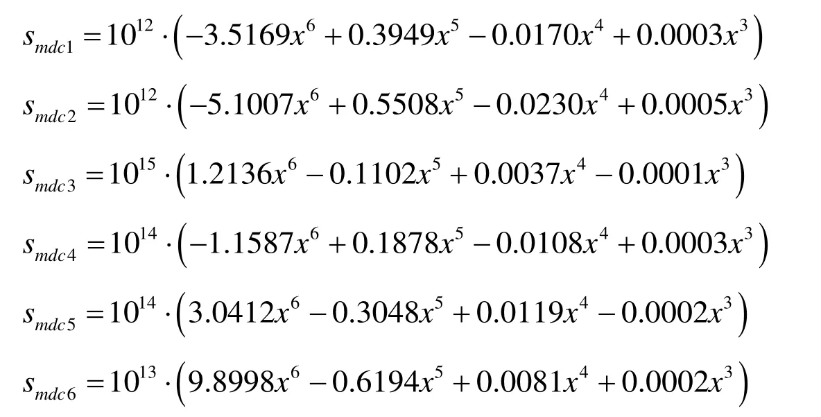
When the multistage face gears are in free vibration,the natural frequency of same order can be changed with crown quantity,and the trend can be fitted by 10 polynomials.The first-order natural frequency firstly increases and then decreases with the increase in crown quantity in a small range.It remains stable under the interval (0,0.015),slightly increases under the interval (0.015,0.018),and obviously decreases under the interval (0.018,0.025).The second-order natural frequency increases slowly and linearly under the interval (0,0.015),obviously decreases under the interval (0.018,0.025),and decreases with small terraces under the interval (0.025,0.03).The trends of third,fourth,and sixth orders are almost the same,and the natural frequency fluctuates with crown quantity.The fifth-order natural frequency remains stable under the interval (0,0.018),and also fluctuates under the interval (0.018,0.03).When extrinsic motivation is applied on the designed gearbox,the natural frequency of multistage face gears,which should be avoided,can be observed in the fitting curve.
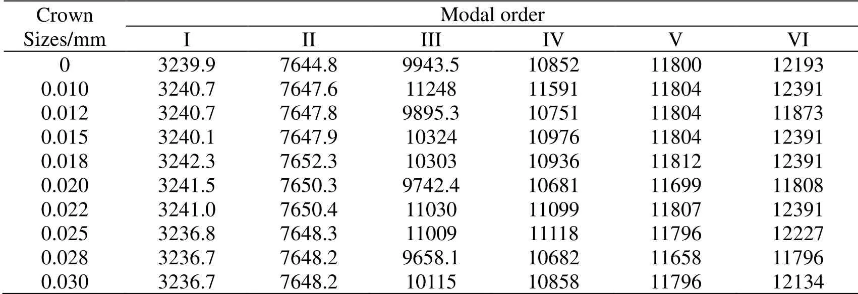
Table 5:Natural frequency of different crown sizes in the first six models
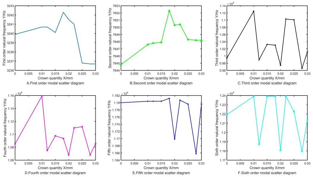
Figure 13:Scatter diagram of different crown quantities in first six models
4.2 Modal characteristic analysis of different tooth surface friction coefficients
Extract the following friction coefficients for modal characteristics analysis:μ=0,0.01,0.015,0.02,0.03,0.1,0.5,1,and 2,which are assumed based on other people's research results or experience values while comprehensively considering the gear material,machining technic and meshing conditions [Kolivand,Li and Kahraman (2010);Wang and Shi (2017)],as shown in Tab.6.
From Tab.6,it shows that the natural frequency of gears under each friction increases with coefficient.The gears’ natural frequencies with different friction coefficients under the same order have a certain trend.The 10 polynomial fitting equations were written and run by MATLAB,to obtain each order constant of polynomial and the scatter plots of each friction coefficient,as shown in Fig.14.
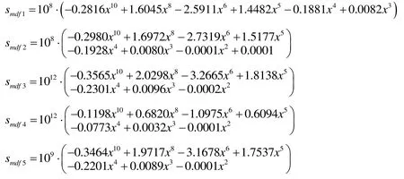


Table 6:Natural frequency of different friction coefficients in the first six models
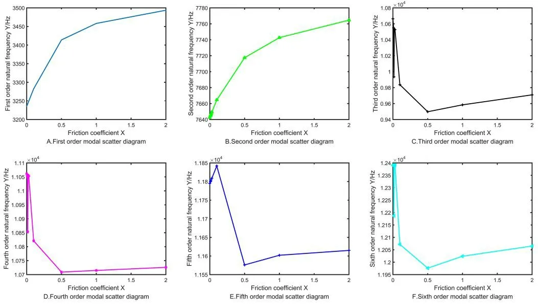
Figure 14:Scatter diagram of different friction coefficients in the first six models
The natural frequency changes with the increase in friction coefficient.The trends of first and second order are almost the same,which increases as a parabola.The trends of third,fourth,fifth,and sixth orders are almost the same too,changing as “Z”.The natural frequency rapidly increases with the friction coefficient under the interval (0,0.015),but significantly decreases under the interval (0.015,0.5),and then slowly increases under the interval (0.5,2).For the surface structure and meshing characteristics of designed multistage face gears,it is necessary to avoid these natural frequencies when applying excitation extrinsic motivation.
5 Tooth surface deviation and contact area measurement
To measure the tooth surface deviation or contact area,it is generally necessary to generate a mesh,where certain measurement points are selected to determine the density according to the measurement requirements.
The values of corresponding measurement points in the original and target states are tested by the measurement software,the corresponding tooth surface traces are drawn by the data machining software,and the deviation of tooth surfaces is calculated according to the error definition.
5.1 Tooth surface detection with three-coordinate measuring instrument
The tooth surfaces are detected using a Spectrum three-coordinate measuring instrument in this study,as shown in Fig.15.
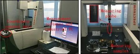
Figure 15:Spectrum three-coordinate measuring platform
According to the coordinate geometry measurement principle,the target measurement object is placed in the three-coordinate measurement space,and the coordinate values of discrete spatial position points of the measurement object are picked up through the kinematic chain between the measuring probe and each axis.Then,the actual tooth surfaces are fitted by proper calculation of these point values to obtain the deviation between the measured and theoretical values.Similarly,based on the newly machined structure,the corresponding tooth surface deviation of free meshing or loading deformation can be obtained by comparing with the measured values in free meshing or load meshing.
In the actual measurement,the three-coordinate measuring instrument can only recognize the point values under the measurement coordinate system.Therefore,the relationship between measurement coordinate system and relative position of gear sample must be determined,which is the fitting of datum plane.
In addition,a reference point is needed to determine the angular orientation of measurement gear sample on the coordinate system,and the reference point is defined as the coincidence point between the theoretical and real tooth surfaces (or the original and measured states tooth surfaces),where the measuring probe should be as close as possible to the measured tooth surface,as shown in Fig.16.
After determining the distance between two coordinate systems and angular orientation,starting from the initial measuring surface,the teeth surfaces of same direction that rotated one circle around the gear axis are detected by the probe.Then,the other teeth surfaces of teeth alveolus are reversely measured around the gear axis to measure the coordinate values of front and back surfaces of each tooth.
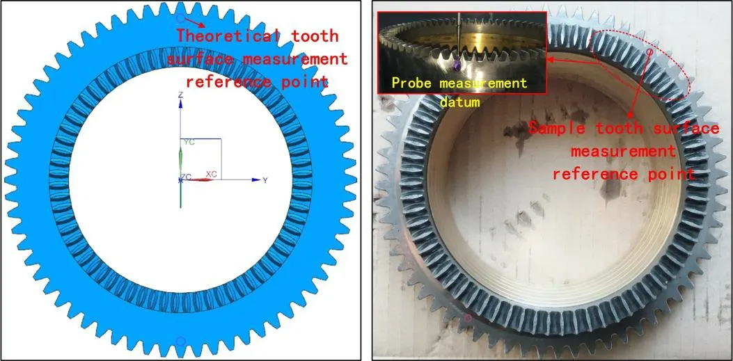
Figure 16:Define measurement reference point
5.2 Detection analysis of tooth surface of face gears
Based on the above analysis,this experiment will detect the machining accuracy,meshing accuracy,and load deformation of each single-stage face gear.The main methods are as follows:the machining accuracy is measured by considering the design parameters of 3D structure as the original state and the machining physical samples as the target measurement state.Then,the meshing precision is measured by taking the processed physical sample as the original state and the sample after the free meshing without load as the target measurement state.Finally,the deviation of load deformation is measured by taking the machining physical sample as the original state and the deformed sample after load as the target measurement state.
5.2.1 Determination of machining accuracy
Inputting the 3D design model,fixing the machining sample on the measuring platform,defining the reference datum,selecting the probe with corresponding precision,projecting the detection area and the detection point density,setting the initial measurement tooth surface,confirming the measurement path and the datum coordinates,and completing the tooth surface topography measurement.
Taking the first-stage face gear (56 teeth) as an example,some measurement results are shown in Tab.7.
Because of space limitation,it is not possible to list all the data of face gears obtained at all stages.By comparing the measured values with the theoretical values,the maximum positive deviation of the tooth surface of the first-stage face gear is 0.055 mm,and the maximum negative deviation is -0.045 mm.The maximum positive deviation of tooth surface of the second-stage face gear is 0.043 mm,and the maximum negative deviation is -0.052 mm.The maximum positive deviation of tooth surface of the third-stage face gear is 0.017 mm,and the maximum negative deviation is -0.036 mm.The machining accuracy basically satisfies the requirements of experimental samples,but still should be significantly improved.

Table 7:Machining accuracy error of face gear samples (mm)
5.2.2 Detection of meshing tooth surface error
With an input speed of 100 rpm,200 rpm,300 rpm,and 500 rpm respectively,the meshing running-in experiments are sufficiently carried out on face gears at all stages without a load.The running-in time of each speed accumulates to more than 10 h.After disassembly,the meshing samples are detected in the same manner.Thus,the results can be obtained by comparing with the machined samples.
The maximum deviation of tooth surface of the first-stage face gear is 0.0095 mm,and the minimum deviation is 0.0027 mm.The maximum deviation of tooth surface of the second-stage face gear is 0.0086 mm,and the minimum deviation is 0.0021 mm.The maximum deviation of tooth surface of the third-stage face gear is 0.0062 mm,and the minimum deviation is 0.0015 mm.
After further analysis of the corresponding data,the maximum deviations mostly occur in the inner radius of face gears,and the minimum deviations mostly occur in the area of outer radius biasing towards the addendum.This indicates that the meshing curves do not reach a steady state,and the teeth surfaces wear are caused by sliding contact,so that leading to a jump in the contact areas.It is necessary to optimize the parabola crown quantities of gears teeth to infinitely approach the ideal contact points.
5.2.3 Measurement of load deformation
After sufficient running-in experiments,with various input speeds,the loads of 3.8 W,19.0 W,and 49.4 W are added to the face gears respectively,and the accumulated running-in time are more than 6 h.After disassembly,the meshing samples are detected in the same manner,as shown in Fig.17.

Figure 17:Detection samples after load deformation
The results can be obtained by comparing with the machined samples:
The maximum deviation of tooth surface of the first-stage face gear is 0.081 mm,and the minimum deviation is 0.019 mm.The maximum deviation of tooth surface of the second-stage face gear is 0.074 mm,and the minimum deviation is 0.022 mm.The maximum deviation of tooth surface of the third-stage face gear is 0.073 mm,and the minimum deviation is 0.029 mm.
The load deviation of tooth surface reflects the depth of impression of contact deformation.After sufficient running-in in the case of a small load,the deformations of gears teeth basically conform to the simulation results of dynamics.The point contact forms a contact ellipse under the load,whose shape and distribution position are not much different for different stages of face gears but decreases as the stages increases.According to the analysis of shapes and deviations of impressions,a certain degree of collision occur in the face gears.The design,machining,and installation accuracy including the crown quantity design,teeth backlash,and teeth pitches are still needed further optimization.
6 Conclusion
Multistage face gears as the core component of a novel transmission mechanism achieved a variable speed with differential gear shifting.The followings conclusions are obtained from this study:
(1) A series of coordinate points of crown surface are constructed by MATLAB,and then the 3D entity and assembly model of multistage face gears are obtained by UG 3D modeling function to achieve the visualization of multistage face gears.
(2) The quasi-static contact characteristics of different crown quantities and friction coefficients are analyzed in detail,and the corresponding trends are concluded.It is proved that the double crown surface method is feasible to improve the meshing contact performance of face gear pair.
(3) In the case of transmission instability of multistage transmission mechanism,the modal analysis is carried out for multistage face gears with different crown quantities and friction coefficients to obtain the corresponding natural frequency and vibration mode.Furthermore,the trend of each order modal frequency was determined.Thus,the natural frequencies can be removed from extrinsic motivation and improve the stability of transmission.
(4) A simulation study of contact characteristics and modal characteristics is carried out for double crown surface and friction coefficients of multistage face gears structure under the quasi-static condition.The results can improve the structural optimization and save research cost.
Acknowledgment:This work was supported by the National Natural Science Foundation of China (grant number 51575191).All authors declare that there is no conflict of interests regarding the manuscript submitted.
The authors would like to thank Miss Tian Xu for free in English Editing;The authors would like to thank MogoEdit Company for modifying the manuscript with native language.
References
Han,J.;Zhu,Y.G.;Xia,L.;Tian,X.Q.(2018):A novel gear flank modification methodology on internal gearing power honing gear machine.Mechanism and Machine Theory,vol.121,pp.669-682.
He,Z.Y.;Lin,T.J.;Luo,T.H.;Deng,T.;Hu,Q.G.(2016):Parametric modeling and contact analysis of helical gears with modifications.Journal of Mechanical Science and Technology,vol.30,pp.4859-4867.
Inoue,T.;Kurokawa,S.(2017):Proposal of a face gear which generates virtual high mesh frequency by addition of grooves on the tooth flank,and the investigation via vibration simulator and actual samples.Precision Engineering Journal of the International Societies for Precision Engineering and Nanotechnology,vol.47,pp.321-332.
Kolivand,M.;Li,S.;Kahraman,A.(2010):Prediction of mechanical gear mesh efficiency of hypoid gear pairs.Mechanism and Machine Theory,vol.45,pp.1568-1582.
Li,Z.M.Q.;Fan,J.H.;Zhu,R.P.(2018):Construction of tooth modeling solutions of face gear drives with an involute pinion.Iranian Journal of Science and Technology-Transactions of Mechanical Engineering,vol.42,pp.35-39.
Li,Z.M.Q.;Ye,W.;Zhang,L.L.;Zhu,R.P.(2016):Effect predictions of star pinion geometry phase adjustments on dynamic load sharing behaviors of differential face gear trains.Journal of Vibroengineering,vol.18,pp.81-92.
Litvin,F.L.;Fuentes,A.;Howkins,M.(2001):Design,generation and TCA of new type of asymmetric face-gear drive with modified geometry.Computer Methods in Applied Mechanics and Engineering,vol.190,pp.5837-5865.
Litvin,F.L.;Fuentes,A.;Zanzi,C.;Pontiggia,M.(2002):Design,generation,and stress analysis of two versions of geometry of face-gear drives.Mechanism and Machine Theory,vol.37,pp.1179-1211.
Liu,J.P.;Shu,X.B.;Kanazawa,H.;Imaoka,K.;Mikkola,A.et al.(2018):A model order reduction method for the simulation of gear contacts based on Arbitrary Lagrangian Eulerian formulation.Computer Methods in Applied Mechanics and Engineering,vol.338,pp.68-96.
Shen,Y.B.;Liu,X.;Li,D.Y.;Li,Z.P.(2018):A method for grinding face gear of double crowned tooth geometry on a multi-axis CNC machine.Mechanism and Machine Theory,vol.121,pp.460-474.
Tran,V.T.;Hsu,R.H.;Tsay,C.B.(2015):Tooth contact analysis for a double-crowned involute helical gear with twist-free tooth flanks generated by dual-lead hob cutters.Journal of Mechanical Design,vol.137.
Tsay,M.F.;Fong,Z.H.(2007):Novel profile modification methodology for moulded face-gear drives.Proceedings of the Institution of Mechanical Engineers Part C-Journal of Mechanical Engineering Science,vol.221,pp.715-725.
Wang,C.;Shi,Z.Y.(2017):A dynamic calculation method of sliding friction losses for a helical gear pair.Journal of the Brazilian Society of Mechanical Sciences and Engineering,vol.39,pp.1521-1528.
Wang,Q.B.;Zhang,Y.M.(2017):A model for analyzing stiffness and stress in a helical gear pair with tooth profile errors.Journal of Vibration and Control,vol.23,pp.272-289.
Zhang,J.;Qi,X.M.;Gou,F.L.;Long,X.D.;Zhang,L.(2017):Parametric design and finite element analysis of involute helical gears.Proceedings of the 2017 6th International Conference on Measurement,Instrumentation and Automation,vol.154,pp.255-260.
Zhou,C.;Chen,C.L.;Gui,L.J.;Fan,Z.J.(2018):A nonlinear multi-point meshing model of spur gears for determining the face load factor.Mechanism and Machine Theory,vol.126,pp.210-224.
 Computer Modeling In Engineering&Sciences2019年2期
- Computer Modeling In Engineering&Sciences的其它文章
- A Graph-Based Reinforcement Learning Method with Converged State Exploration and Exploitation
- Context-Based Intelligent Scheduling and Knowledge Push Algorithms for AR-Assist Communication Network Maintenance
- Improved Particle Swarm Optimization for Selection of Shield Tunneling Parameter Values
- Solving the Nonlinear Variable Order Fractional Differential Equations by Using Euler Wavelets
- Analysis of OSA Syndrome from PPG Signal Using CART-PSO Classifier with Time Domain and Frequency Domain Features
- Numerical Simulation and Experimental Studies on Elastic-Plastic Fatigue Crack Growth
