Numerical Shock Viscosity for Impact Analysis Using ALE Formulation
SouliMhamed,PaulDuBoisandEssamAl-Bahkali
Abstract: When the simulation takes account of dissipative mechanisms, e.g.heat conduction and viscosity, the shocks become smeared out to produce thin layers of rapidly and continuously varying energy, density, pressure and velocity rather than discrete surfaces of mathematical discontinuity.In the mid twentieth century, Von Neumann and Richtmyer suggested the use of a viscous pressure term (bulk viscosity) in the equilibrium equations for ideal gases in order to examine the shock while avoiding numerical oscillations at the shock front.When the bulk viscosity is included in the conservation equations, the comprehensive physics present a continuous solution satisfying the Rankine-Hugoniot conditions.Nevertheless, the published literature includes few engineering and research studies presenting the novel equilibrium equations in which the incorporation of bulk viscosity generates a continuous solution in keeping with conservation laws.The present work is aimed at demonstrating that the artificial bulk viscosity defined by Von Neumann and Richtmyer is also applicable to fluids described by a density-linear equation of state, that the novel equations present a continuous solution, and that a shock layer of the same order as the computational grid is generated.Although the method has been employed and mathematically proven for onedimensional flow, it would seem to be just as relevant to the analysis of more complex flow dynamics and fluid structure interactions via an application of the Arbitrary Lagrangian Eulerian (ALE) formulation.
Keywords: Shock wave, fluid structure interaction, ALE.
1 Introduction
Computational engineering for academic and industrial applications is becoming increasingly concerned with the simulation of complex flows and fluid structure interaction (FSI) analysis.Two distinct and significant issues are encountered when solving such problems, namely high mesh distortion and the bogus oscillations in the shock front that emerge in shock problems.
The narrow shock thickness, which encompasses just a few collisions within the mean free path of the surrounding gas, means that accurate results can be obtained only by adjusting the mesh size so that the shock can be resolved by each individual element.This approach is impractical because the algorithm demands an immense quantity of computational time.Moreover, the equations of conservation of energy, momentum, and mass across a shock demand that kinetic energy is converted to heat or internal energy.In order to dissipate the surplus energy in the lack of physical viscosity close to the shock,an artificial hypothetical viscosity was incorporated.This caused the shock to thicken such that the discontinuity became smeared into an even transition zone, thereby enabling the computational mesh to capture of the shock.
A number of approaches to solving mesh distortion have been examined in the literature.For example, meshless approaches such as smooth particle hydrodynamics (SPH) have been proposed in which the fluid domain is modelled by particles with zero connectivity[Al-Bahkali, Elkanani and Souli (2015); Al-Bahkali, Souli and Al-Bahkali (2015)].Alternatively, the problem has been circumvented by application of the Arbitrary Lagrangian Eulerian (ALE) formulation [Souli, Kultsepand, Al-bahkali et al.(2016);Souli, Al-Bahkali, Albahkali et al.(2017)].The Lagrangian formulation, in which the mesh moves along with the material, is primarily applied to solid mechanics problems but is also applicable to FSI problems [Moatamedi, Souli and Al-Bahkali (2014); Elkanani,Al-Bahkali and Souli (2017); Fan, Yao, Yang et al.(2018)].It can accurately solve the material boundary and fluid structure interface for small deformations, its primary limitation being mesh distortion in the case of large deformations and structural motion for which the fluid is solved on a moving domain.Numerous methods for solving FSI problems have been investigated, with the ALE formulation being among the most frequently used.This approach has enabled the effective simulation of fluids undergoing bulk motion in circumstances relating to the aeronautic industry (turbulence due to collision with a bird) and to the automotive industry (fuel sloshing in the tank).Previously investigated methods for solving FSI problems include Lagrangian formulations and ALE multi-material formulation [Aquelet, Souli and Olovson (2005)].After validation by experimental testing, the simulation could be employed as a design tool for structural enhancement.Hence, the study focused on validating an approach using an explicit finite element code for structural dynamics to enable simulation of FSIs where an ALE or Eulerian mesh can be defined.In terms of the algorithm, a fluid element can incorporate one or more fluid materials, e.g.when considering structural inflation in the surrounding atmosphere, or when considering a structure containing pressurised gas on the inside and surrounded by the atmosphere on the outside.State variables are calculated and cached for each material within each element during the simulation.The interface between different materials within each element is captured by an interface tracking algorithm based on Young's method.This approach was used effectively to model a wide range of academic and industrial applications including the sloshing tank problem.
In the present work, the ALE formulation is described in a moving mesh and applied by means of an explicit time integration approach, using the advection algorithms to solve the conservation of energy, momentum and mass.Previous studies have well demonstrated that extreme mesh distortion arises due to significant levels of spurious oscillations close to the shock in the absence of physical viscosity, as illustrated in Section 2 of the present work.These levels of bogus oscillation are circumvented in the treatment shock problems by incorporating a viscous pressure in the equilibrium equations.Section 3 of this paper presents a rigorous mathematical proof, in a onedimensional case, that the novel equilibrium equations describe a rapid but continuous variation of pressure, density and velocity across the shock.While the approach has been applied to one-dimensional flow, it is nevertheless appropriate to the examination of more complex flow and to FSI problems.Hence, the final section of the present paper is aimed at an application of the approach to a three-dimensional case.
2 The ALE formulation
The modelling of fluid problems involving interfaces between different materials (e.g.a gas and the surrounding atmosphere) is facilitated by applying a Lagrangian mesh.Where the analysis of complicated tank geometry is needed, however, this approach is challenging because the mesh distortion requires the use of multiple re-meshing stages in order to continue the computation.Although the Eulerian formulation provides an alternative method, the move from the Lagrangian to the Eulerian formulation introduces two problems, namely that of interface tracking [Young (1982)] and that of advection or transfer of fluid material across element boundaries.
These issues are addressed by using an explicit finite element approach for the Lagrangian phase and a finite volume (flux) approach for the advection phase.A number of explicit codes are available.The explicit finite element method is fully detailed by Benson [Benson (1992)].To broaden the range of applications that cannot be addressed by the Lagrangian formulation alone, the advection phase is developed.Present applications include sloshing motions with an unconstrained surface and high velocity impacts where the target is treated as a fluid in order to generate a more realistic representation of the impact event by considering large deformations.
The ALE formulation incorporates both the pure Eulerian and pure Lagrangian formulations.In the pure Lagrangian approach, the mesh moves with the material in order to facilitate interface tracking and the application of boundary conditions.In the Eulerian approach, the mesh remains stationary as the material passes through it.While this makes it difficult to track boundary conditions and interfaces, the unchanging mesh avoids the problem of mesh distortion.While the pure Eulerian formulation is not applicable to solid mechanics because it can only consider one material in an element, the ALE formulation is regarded as able to consider more than one material.
The ALE approach introduces an arbitrary referent coordinate along with the Eulerian and Lagrangian coordinates.Eq.(1) gives the material derivative with respect to the reference coordinate:

whereXi= the Lagrangian coordinate,xi=the Eulerian coordinate andwi=the relative velocity.
The ALE equations are then derived by substituting the relationship between the material time derivative and the reference configuration time derivative.The equations are simplified by introducing the relative velocityw=v–u, wherevdenotes the velocity of the material andudenotes the velocity of the mesh.The central equations of the ALE formulation are then given by conservation equations of mass (2), momentum (3) and energy (4):
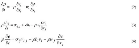
In order for the problem to be well stated, initial and boundary conditions must be imposed.Hence, a robust expression of the problem controlling Newtonian fluid flow in a fixed domain incorporates the central equations along with appropriate initial and boundary conditions.With respect to momentum, the central equations for the fluid problem include the ALE description of the Navier-Stokes Eq.(3).
The Eulerian equations frequently employed in computational fluid dynamics (CFD) are obtained by assuming a reference configuration with zero velocity; hence the relative velocity between reference configuration and the material is equal to the material velocity.The movement of material past the mesh is considered by the relative velocity term in Eqs.(3) and (4); this is known as the advective term.This extra term in the ALE equations makes their numerical solution significantly challenging in comparison to the Lagrangian equations in which the relative velocity is zero.
For efficiency, and in order to avoid locking, Eqs.(2) to (4) use the discrete approach of one-point integration, with the zero energy modes being controlled by an hourglass viscosity [Benson (1992)].Von Neumann et al.[Von Neumann and Richtmyer (1950)]applied a shock viscosity with linear and quadratic terms in order to resolve the shock wave, adding a pressure term to the energy Eq.(4).The central difference method advances the resolution in time, giving a second-order time accuracy by means of an explicit approach in time; the displacement and velocity are updated for each node by explicit time integration.
Because it permits arbitrarily large deformations and the evolution of unconstrained surfaces, the multi-materials formulation is useful for resolving a wide variety of nonlinear fluid and solid mechanics problems.The Lagrangian stage in the volume of fluid(VOF) method is easily realised via an explicit ALE finite element approach.Special consideration must be applied to the partially voided element prior to advection; the volume fraction of the partially filled element satisfies the conditionVf≤1 and the total stress (σ) is weighted according to the volume fractionσf=σ.Vf.
The transfer of mass, momentum and internal energy across cell boundaries is calculated in the advection phase.This can be regarded as a re-mapping of the distorted mesh of the Lagrangian phase back to its initial state (Eulerian formulation) or to an arbitrary undistorted mesh (ALE formulation).This advection phase involves the solution of a hyperbolic or transport problem in which the density, momentum and internal energy per unit volume are all variables.The numerical method for solving the equations is described by Von Neumann et al.[Von Neumann and Richtmyer (1950)], including a first order advection approach (the donor cell algorithm) and a second order advection approach also described by Young [Young (1982)] (the Van Leer algorithm).For example, the conservation of mass is given by Eq.(5):

The present paper does not set out to describe the various algorithms used to solve this equation, as these have been detailed by Aquelet et al.and Qzdemir et al.[Aquelet, Souli and Olovson (2005); Ozdemir, Souli and Fahjan (2010)].
3 Artificial shock viscosity
Shocks are considered mathematically as discontinuities in the time-lines of the variables energy, pressure and velocity.However, shocks physically display a limited thickness encompassing just a few collisions within the mean free path within the surrounding gas.According to Souli et al.[Souli and Gabrys (2012)], the mean free path in air at standard temperature and pressure (STP) is approximately 70 nm.Consequently, the mesh size must be adjusted such that the shock can be resolved by each discrete element in order to maintain the accuracy of the analysis.This approach is impractical because it requires the algorithm to handle an extreme quantity of CPU time; hence the shock front cannot be numerically represented by any mesh.
Shock phenomena can be mathematically and numerically described by considering the equilibrium hydrodynamic equations known as Navier-Stokes or Euler equations, which have previously been applied to a non-viscous fluid:

The scheme of Eqs.(6)-(8) is completed by applying an equation of state for pressure and their significance is that, mathematically, they lead to the development of a shock; their solution is non-continuous and the problem is only well-stated when the shock conditions are met.These Rankine Hugoniot conditions define the relationship between states on each side of the shock in terms of energy, momentum and mass conservation.As shown in Fig.1, they are derived by applying the conservation laws as integrals across a control volume that encompasses the shock.

Figure 1: Application of Eqs.(6)-(8) to shock development of density, velocity and pressure
Significant levels of spurious oscillations arise close to the shock in the absence of physical viscosity.These oscillations frequently occur when continuous shape functions are employed in the finite element method (FEM) to interpolate discontinuous functions.This phenomenon can be demonstrated by examining the propagation of a pressure wave in a tube of length 10 m when an initial pressure of 0.994 is augmented by a pressure pulse of 1 bar applied at one end of the tube (Fig.2).This can be treated as a onedimensional case by constraining the velocities on both the vertical and normal directions.

Figure 2: Schematic of an exemplary shock problem
The mesh must be convergent, smooth and at right-angles to the pressure wave front for an accurate prediction of the peak pressure to be obtained.If there is any irregularity in the mesh, a spurious reflection will be generated when the pressure wave impinges upon the irregularity.
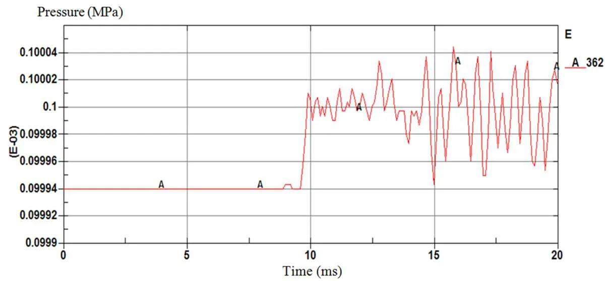
Figure 3: Pressure-time evolution in the absence of numerical viscosity
According to Von Neumann et al.[Von Neumann and Richtmyer (1950)], numerical oscillations at the shock front can be avoided in the mathematical treatment of an ideal gas by introducing a viscous pressure term (bulk viscosity) into Eqs.(6) to (8).With the incorporation of a relevant viscous pressure (Q), the conservation Eqs.(9)-(11) describe a complete physics with a continuous solution:

the viscous pressureQbeing defined by Eq.(12):

wherev=the fluid velocity,l=a typical shock smearing length andqis a scaling factor for the smearing thickness.
While the bulk viscosity is incorporated into each element under compression, no addition is made for elements in tension.When the bulk viscosity is included in Eq.(11),the set of Eqs.(9)-(11) have a continuous solution that meets the Rankine Hugoniot conditions and the requirements of the conservation laws.
In detail, the viscous pressure functions by converting the mechanical energy irreversibly into heat and facilitates the numerical simulation of shock fronts when the following conditions are met: (i) the computational grid is scaled to the thickness of the shock layer,regardless of the type of material and the shock strength; (ii) outside the shock layer the Hugoniot conditions hold and the bulk viscosity has negligible effect; (iii) energy, mass and momentum are precisely conserved across the shock front; and (iv) the conservation Eqs.(9) to (11) (incorporating the bulk viscosity)Qpossess a continuous solution.
When this approach is applied to the problem illustrated in Fig.2, Fig.4 indicates the pressure obtained both in the presence and absence of the viscous pressure termQ.
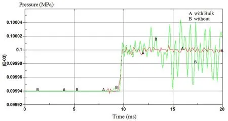
Figure 4: Pressure-time evolution in the presence and absence of viscous pressure
These examples demonstrate that including the bulk viscosity in the non-viscous fluid simulation results in a uniform solution for impact problems while avoiding significant levels of spurious oscillations in the shock front.The majority of academic and industrial dynamic analysis software packages cite Von Neumann et al.[Von Neumann and Richtmyer (1950)] without providing the user with any detailed guidelines.Furthermore,with respect a density-linear equation of state, there is no published work demonstrating that Eqs.9-11 with the addition of bulk viscosity (as defined by Eq.(12)) provide a continuous solution that meets the laws of conservation.The present paper is therefore aimed at demonstrating these characteristics of Eqs.(9-11) and that the shock layer has the same order of magnitude as the computational grid.
Graphical representations of pressure along the computational domain can help accentuate the extreme oscillations generated close to a shock, as demonstrated by Figs.5, 6 and 7.These graphs indicate that oscillations near the shock can be significantly decreased by incorporation of the bulk viscosity into the hydrodynamic equations.Moreover, adding the viscous pressure term (also known as bulk viscosity or Richmyer and Von Newman viscosity) to the hydrodynamic equilibrium equations can damp out bogus high frequency oscillations without compromising accuracy.This technique has found use in numerous nonlinear software packages, including LS-DYNA [Hallquist (2013)].
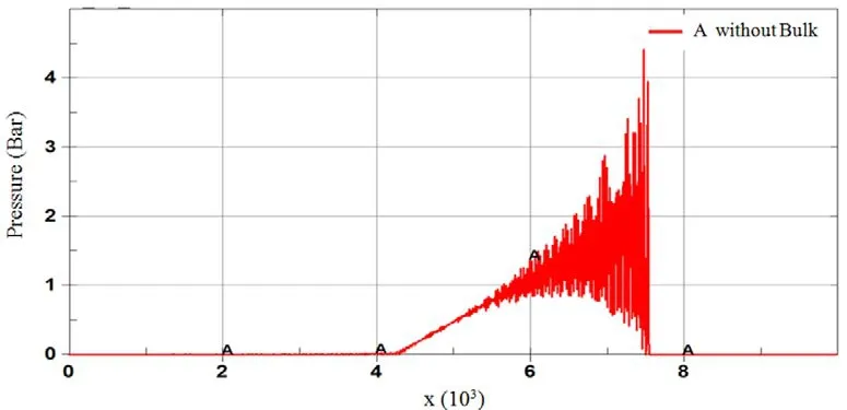
Figure 5: Plot of pressure along the bar (mm) in the absence of numerical viscosity

Figure 6: Plot of pressure along the bar (mm) including numerical viscosity
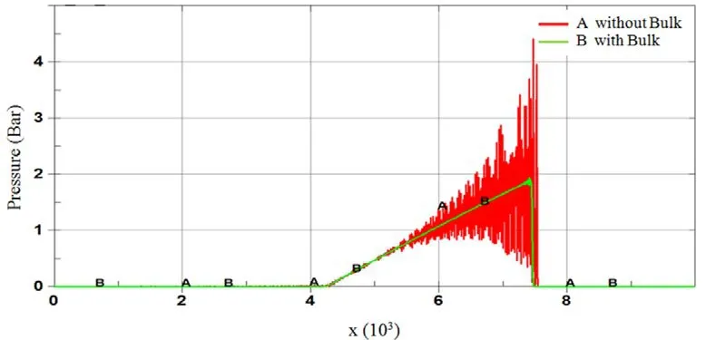
Figure 7: Pressure plotted in the presence and absence of viscosity on the same chart
As shown in Fig.8, a plot of the pressure as a function of volume, or change of volume,for a specific element can be very helpful in evaluating the bulk viscosityQ.This plot indicates the energy-loss due to viscous pressure in the course of shock-loading and unloading.The following details can be noted: (i) Shock-loading follows Rayleigh line A from 0 (the reference state) to point 1, while unloading returns to 0 starting from point 1 and following the isentropic line B.(ii) The total amount of energy between the loading and unloading routes was dispersed by the shock.(iii) The viscous pressure (Q) within the element is equal to the difference in pressure between lines A and B.

Figure 8: plot of shock loading and unloading within a single element
3.1 The mathematical treatment of artificial shock viscosity
Incorporation of the viscous pressure into the equilibrium equations facilitates a mathematical demonstration of a continuous solution in which the shock is smeared over a thickness of approximatelyq.l(Eq.(12)).
For simplicity, a one-dimensional equation of equilibrium is considered with a densitylinear equation of state for the pressure.Taking the specific volumeV= 1/ρ, the mass Eq.(9) gives:

Applying conservation of mass (ρ.l=ρ0.l0) then gives:

Hence solutions are sought in which the shock front propagates with constant velocityU.However, it is mathematically more useful to employ a change of variable with constant shock speed relative to the medium at rest:

Applying Eqs.(16) and (17) to the conservation Eqs.(9) and (10) gives the altered conservation Eqs.(18) and (19):
These two equations can be combined to give conservation of mass and momentum in terms of the introduced variablew:

To summarise, a new conservation of momentum equation is derived usingV= 1/ρand this leads to a simple equation forVin terms ofw.This equation will have a continuous solution that can be analytically solved.
From Eq.(18):

whereCis a constant relative to the variablew.which must now be defined as:

The let bulk viscosityQin Eq.(15) can now be expressed in terms of the introduced variablew, as:

The effectiveness of the quadratic bulk viscosity can be demonstrated by applying a density-linear equation of state for the pressure:

Applying specific volumeV= 1/ρandV0= 1/ρ0then gives:

Inserting the pressure termP(Eq.(2( 5) into the momentum Eq.(22) then gives:

Far from the shockQ= 0 Eq.(26) gives:

whenV=V0, and

whenV=V1.
Inserting the expression forCfrom Eq.(27) into Eq.(28) gives:

Applying the expression forQfrom Eq.(23) and the expression forCfrom Eq.(27) to Eq.(28) then gives:

from which application of the expression forin Eq.(29) gives the following conventional differential equation forVin terms ofw:

Eq.(30) can be re-written as a conventional differential equation, thus:

This equation has a continuous solution forVin terms ofwand can be integrated to indicate the form of the shock front:

In Fig.9, the mesh size is represented numerically by the specific lengthlin terms of a dimensionless constantq(which is close to 1) and the shock layer thickness can be represented by 3 to 5 mesh elements.Eq.(31) clearly demonstrates that the shock layer is not influenced by the shock strength or by the bulk modulusKof the material.Moreover,it can be readily demonstrated that Eq.(32) represents a solution of the conventional differential Eq.(31) by obtaining the value of the specific volumeVwith respect towand multiplying by 2.
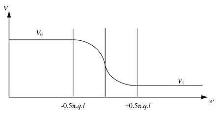
Figure 9: Specific volume as a continuous function of w
4 Numerical simulation
In the previous sections the viscous pressure was applied to a simple one-dimensional case; however, the approach is also generally applicable to shock problems in three dimensions.One example would be a shock produced by detonation of a high explosive.This process involves a rapid chemical reaction that transforms the material into a gas at high pressure.In terms of material constitution, the gas is regarded as having zero viscosity and zero shear, and the Jones-Wilkins-Lee (JWL) equation of state is applied to calculate the pressure.While numerous equations of state have been put forward for the gaseous detonation products, ranging from basic theoretical to empirical equations with numerous tuneable parameters, the JWL equation is frequently applied to explosive materials.
In the present work 8-node elements were used to model the explosive.The equation of state governs the correlation between the blast pressure, volume change and internal energy.The following form of the JWL equation was applied:

wherep= pressure andV= relative volume, i.e.:

such thatv=current element volume and=initial element volume.
Tab.1 defines the material constants A, B,R1,R2, and ω that appear in Eq.(33).These parameters are based on the cylinder expansion (CYLEX) test under controlled conditions for a C-4 composition explosive.
Such simulations are particularly important in structural design for blast-load resistance and protection from damage by munitions and fragments of blast debris.Where the final goal is the development of resistant structures, the potential applications of the numerical simulation include the enhancement of shape design by optimised design methodologies[Barras, Souli and Aquelet (2012); Souli and Zolesion (1993)], and optimisation of materials [Erchiqui, Souli and Ben Yedder (2007); Ozdemir, Souli and Fahjan (2010);Khan, Moatamedi and Souli (2008)].After validation by test results, the simulation can be employed as a design tool for enhancing the structure of the system under consideration.

Table 1: Material performance properties applied to C-4 explosive

Figure 10: Mesh description of explosive problem
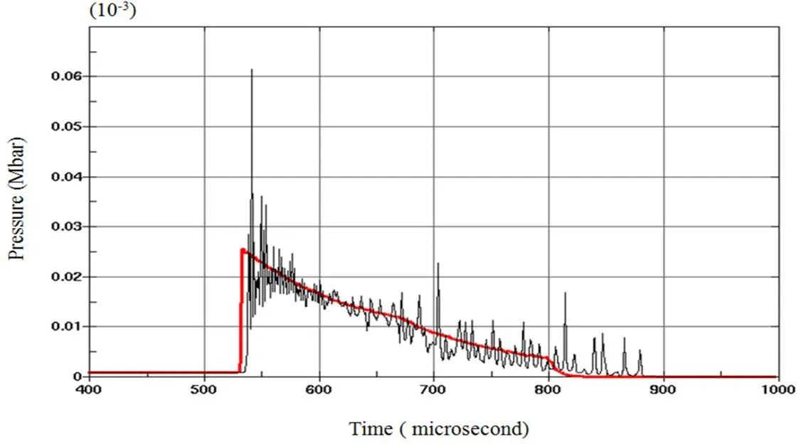
Figure 11: Pressure-time evolution in the presence and absence of the bulk viscosity Q
5 Conclusion
The present paper has described a numerical and mathematical treatment of bulk viscosity to generate a density-linear equation of state.Although bulk viscosity finds application in numerous industrial and academic dynamic codes, there is presently no description of shock smearing in the academic literature or in engineering manuals.To plainly illustrate the benefits of bulk viscosity, the present discussion employed a basic one-dimensional case in which a shock was generated by propagation of a pressure wave in a compressible fluid.The incorporation of a viscous pressure term into the equilibrium equations significantly limited the occurrence of spurious oscillations in the shock front by broadening the shock across a few mesh elements.Although the approach was mathematically described for a one-dimensional hydrodynamic case, it has also found effective application to more complicated cases such as high impacts and detonation of explosives in air or under water.In the present paper, solve complex a re-meshing technique method is described for the solution of three-dimensional problems.The ALE method is developed on the basis of independent movement of the finite element mesh relative to the material.The freedom of mesh movement afforded by the ALE method combines the advantages of both the Eulerian and Lagrangian approaches.
Acknowledgment:This project was supported by King Saud University, Deanship of Scientific Research, College of Engineering Research Center.
 Computer Modeling In Engineering&Sciences2018年10期
- Computer Modeling In Engineering&Sciences的其它文章
- Increasing Distance Increasing Bits Substitution (IDIBS)Algorithm for Implementation of VTVB Steganography
- Structural Design and Numerical Analysis of a Novel Biodegradable Zinc Alloy Stent
- Improved Teaching-Learning-Based Optimization Algorithm for Modeling NOX Emissions of a Boiler
- A Finite Element Study of the Influence of Graphite Nodule Characteristics on a Subsurface Crack in a Ductile Cast Iron Matrix under a Contact Load
- Form Finding and Collapse Analysis of Cable Nets Under Dynamic Loads Based on Finite Particle Method
- Analysis of High-Cr Cast Iron/Low Carbon Steel Wear-resistant Laminated Composite Plate Prepared by Hot-rolled Symmetrical Billet
