Form Finding and Collapse Analysis of Cable Nets Under Dynamic Loads Based on Finite Particle Method
Ying Yu , Ping Xia and Chunwei Yang
Abstract: This paper presents form finding and collapse analysis of cable net structure under strong wind using the finite particle method (FPM).As a kind of particle method,the theoretical fundamentals of the FPM are given.Methods to handle geometric and material nonlinearities of cable element are proposed.The fracture criterion and model for cable element are built to simulate the failure of cable nets.The form-finding and load analysis of two cable nets are then performed in order to initialize the successive of nonlinear analysis.The failure progress of cable nets under dynamic loads is simulated,and the dynamic responses of the typical fracture element are given in details.Analyses of the energy variations during the collapse process also show the failure mechanisms of cable nets, which is useful for the structure collapse resistance design.The numerical applications highlight the capability of the proposed procedure to solve complicate collapse problems with the FPM.
Keywords: Finite Particle Method (FPM), cable net, fracture, form finding.
1 Introduction
Because of light weight and large span, safety of cable nets has been threatened due to rising possibility of extreme bad weather.This kind of structures is very sensitive to the wind, especially fluctuating wind, which may cause obvious structural vibration and deformation, or even partial or total collapse.During the last decades, many different approaches have been proposed to deal with the form finding [Veenendaal and Block(2012); Li, Deng and Tang (2017); Yang, Zhang and Li (2018)], construction [Zhang,Sun and Jiang (2018); Guan, Zhu and Guo (2016)], nonlinearity [Wu, Deng and Zhu(2018); Guo and Zhou (2016)] of cable nets, such as finite element method (FEM)[Zhang, Gao and Liu (2016); Chen, Sun and Feng (2018)], force density method (FDM)[Greco and Cuomo (2012); Xu, Wang and Luo (2018) ], dynamic relaxation (DR)[Namadchi and Alamatian (2017); Mohammad and Hossein (2016)], and so on.However,the collapse analysis of this kind of structure is relatively small.The reason is that the structural collapse is a dynamic instability process, covering many complex structural problems, such as geometric nonlinearity, material nonlinearity, and component fracture.To solve these problems, the existing numerical methods need to be modified or cooperate with other methods [Lynn and Isobe (2007); Mashhadi and Saffari (2017); Guo,pseudo-dynamic process, since the geometry is updated in each time step [Yang, Zhang and Li (2018)].However, other than form finding, the DR method is seldom used in other nonlinear analysis for its limitation in the physics assumption.The FEM is very powerful in the structure behavior simulation and has been wildly used in many engineering fields.But in terms of form finding of cable nets, the results from the FEM are sensitive to the initial state of the structure.If the initial configuration is far away from the equilibrium position, the form finding results may be not the reasonable shape.For the fracture simulations, due to the limitation of continuous meshes, the structure needs to be remeshed after the fracture happens, which is time consumed [Lynn and Isobe (2007)].
In the paper, the finite particle method (FPM) is used in the collapse analysis of cable nets under strong wind.Different from traditional analytical method, this method models the analyzed body as finite particles other than continuous mathematical body.The motion of all particles follows Newton’s second law.And particles are all in dynamic equilibrium under internal and external forces.It is shown that applying the exact equilibrium conditions leads to a form finding method that is very similar to the DR method, but yields significant differences in basic equation and fracture simulation.
For form finding of cable nets, the FPM is as effective as the other two methods.What is more, the FPM is superior for the collapse analysis of cable nets for the following reasons:(1) This method is a dynamic analysis framework; (2) Strategies for addressing geometric and material nonlinearity are simple and straightforward; (3) Fictitious motion is used to handle geometric problems without iteration; (4) As a kind of particle method, particles are free to separate from each other, which leads to convenience in fracture simulation.Recently, the FPM has been proved efficient in dynamic fracture analysis and progressive failure analysis of space structures [Yu, Zhao and Luo (2013); Yu and Zhu (2016); Yang and Luo (2014); Zheng and Fan (2018)].The remainder of this paper is organized as follows.The fundamentals of the FPM are briefly described.Formulations and models for analyzing geometrical nonlinearities, material nonlinearities and member fracture of cable nets are illustrated using the FPM.Then, the form-finding, load analysis and collapse simulation of two cable nets are performed using the FPM.Analysis of internal force and energy variations during the collapse process show the failure mechanisms of the cable nets under strong wind.Zhou and Zhou (2018)].And the solving process is very complicated.Therefore, an easy approach is required to solve these problems in structural collapse analysis.
As an effective form finding method, the DR method discretizes the analyzed domain as nodes with lumped mass and defines the relationship between nodes with stiffness that also be used in the FEM.Under the external force or internal prestress, the nodes of the structure oscillate near the equilibrium position.Iterations are needed to solve the
2 Finite particle method
2.1 Particle motion equation
A cable net can be modeled as particles and elements using the FPM, as shown in Fig.1.The structural mass is assumed to be represented by each particle.Particles are connected by elements, which have no mass.Elemental deformation indicates variations in displacements of the particles connected by the elements.Following the Newton’s second law, the motion equation of an arbitrary particle α is

Where, Mαis the mass matrix,is the acceleration vector, andandare the external and internal force vector of particleα.The parameter Fαintequals the summation of the internal nodal forces exerted by the elements connected to the particle α.Explicit time integration with a simple central difference is suggested to solve Eq.(1) in this study,so no iterations are needed in solution. The details of solving particle motion equation refer to Yu et al.[Yu, Paulino and Luo (2011)].

Figure 1: FPM model of a cable net
2.2 FPM for modeling geometric nonlinearity
Pre-tensioned cable nets are geometrically nonlinear problems.As shown in Fig.2, the fictitious motion is illustrated to calculate the particle internal force with the consideration of geometric nonlinearity.From timetato timetb, the reference configuration of element MN is its configuration at timeta.The effects of geometric variations within the time step Δtis quite small.To remove the rigid body motion of element MN, fictions motions are used for this purpose [Yu, Paulino and Luo (2011)].First, we assume that the element M’N’ at timetbhas a fictitious translation (-ΔxM) and fictitious reversed rotation (-Δθ).ΔxMand Δθare the relative displacements and rotations of particle M within the time step Δt, respectively.
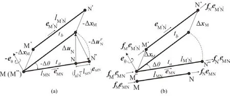
Figure 2: Illustration of fictitious motion: (a) Reversed motion; (b) Forward motion
Then, element M′N′ is displaced to the position M′′N ′′, as displayed in Fig.2(a).At this configuration, the internal force of element MN is determined.The incremental deformation displacement of MNcan be determined by Goldstein [Goldstein (2002)]

However, the deformation of the cable element is only related to the variations of the cable length.And the cable element needs to be under tension.So instead of Eq.(2), the internal force of the cable element for this configuration is obtained as follows,

where, fais the internal force of element MN at timeta, Δfais the incremental internal force of element MN at timetb,σais axial stress at timeta,Aais section area of element MN,Eis the Young’s modulus,ΔLis length variations of element MN between timetaandtb,is the length of element MN at timeta, eMNis the directional vector of Element MN at timeta.
Then, let the element MN have a forward rotation Δθand a translation Δx, and return to its original position.Since rigid body motion only changes the direction of the element axial force, the real element axial force can be determined as

2.3 FPM for modeling material nonlinearity
According to Eq.(1), material nonlinearity only affects how to determine the internal particle force, and the basic solution frame is not changed.If a nonlinear constitutive modelσ=E(ε)is considered here, the loading-unloading state of the cable element should be recorded in each time step.Then, the internal force of the element can still be determined by Eq.(3) explicitly according to the element state in the precious step.
According to experiments of general steel cable [Duan, Qiu and Zhang (2009)], an ideal elastic-plastic constitutive model as shown in Fig.3 is adopted to represent the relationship between stressσand strainεof the cable element.The model is explained as follows:
1) If a cable is initially loaded, thenσ-εmodel follows a straight line with stiffnessE(Eis the Young’s modulus). If the axial strain reaches the material’s yield value,εy,the element enters plastic state.
2) If then the cable is unloaded, the deformation of the cable needs to be checked first.IfTheσ-εmodel returns along the loading relationship with the stiffnessE.is the length of the cable at the current time step,is original length of the cable,is the Residual deformation of the cable after then-th unloading from the plastic phase.Ifthe cable is slack.Therefore, the internal force of the cable turns to be zero.
3) If the slack cable is reloaded, Theσ-εmodel follows the unloading model until it reaches the aforementioned maximalubsequently, Theσ-εmodel enters the plastic phase again. If the axial tensile strain is bigger than the critical value, fracture of the cable element happens.Depending on the type of the cable, the critical axial tensile strainvaries from 1% to 5.5%. In this work,is suggested to be 4.5%for safety consideration.
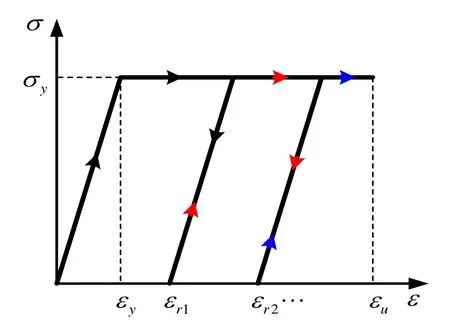
Figure 3: Constitutive model for a cable element
2.4 FPM for modeling cable fracture
The cable fracture model is introduced in this section.FPM models a cable element with two particles and one element, no crack propagations are considered in this work.As shown in Fig.4, if element S reaches the fracture criterion, then check the force of both particle A and particle B.If the force of Particle B is bigger, then fracture happens on particle B.Then generate a new particle B′at the same location of Particle B.And the element S is separated from Particle B.If the forces on the two particles are equal, then fracture happens on both ends.
After the fracture happens, the motions of both the newly added particles and the corresponding original particles still follow the basic motion equations.Only the properties of these particles, such as mass and internal force, need to be updated according to the new topology.Details refer to Yu et al.[Yu, Paulino and Luo (2011)].
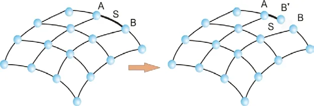
Figure 4: Structural model after fracture
2.5 FPM for analysis of cable nets
The principle of form follows force is particularly relevant in cable nets that transfer their loads purely through axial forces.These form-active shapes are not known in advance,which is determined by forces and vice versa.Therefore, to analyze cable nets, formfinding and load analysis are necessary.The analysis procedure of cable nets using the FPM is as follows,
1) Set the initial geometry and prestress.Use Eq.(1) to calculate the particle position with small elastic modulus and virtual mass.Then, an ideal configuration of the cable net with given prestress is obtained.However, the material property of the structure used in this analysis is unreal.So the initial length of the cable element without prestress needs to be determined to get the real physical strain of the cable net.
2) Based on the ideal configuration after form finding, release prestress and constraints.Use Eq.(1) to calculate the particle position with real elastic modulus and mass.Then, the initial length of the cable element can be obtained when the structure reach equilibrium.
3) Apply load to the pretensioned cable net with ideal configuration and real material property.Use Eq.(1) to calculate the particle position and analyze the structural behavior under external loads.
Using the FPM, the initial geometry of the structure does not need to be close to the final form.The procedure of form finding by the FPM is very similar to the DR, but yields significant differences in the following collapse simulation.
3 Simulation of strong wind
Since this work is focus on the form finding and collapse simulation using the FPM, the aerodynamic admittance and aero elastic of cable nets under strong wind are not considered here [Zhong, Li and Ma (2018); Massaro and Graham (2015]].The wind of the cable net is simplified as rigid roof.A simplified method for wind simulation uses a number of linear combinations of random former variables to calculate the future random variables.It is adopted in this work to simulate wind random process of Davenport wind speed power spectrum [Seely and Bruce (2015)].Then, time history of wind speed and wind pressure can be obtained to analyze the behavior of cable nets under strong wind.
Wind speed of a certain point can be calculated based on Davenport empirical formula,

where,Suis the fluctuating wind power spectrum;nis the fluctuating wind frequency;U0is the average wind speed at a height of 10 m;kis the coefficient of surface roughness.
If wind is assumed to be incompressible gas, the fluctuating wind power spectrum can be converted to pressure spectrum using the Bernoulli equation.Then the relationship between wind speed U and wind pressureωis as follows

where,ρis the mass density.
After obtaining the wind pressure, it needs to be converted to the particle force.The wind loadfkon each particle depends on the area covered by the particle and the shape coefficient of the structure.fkcan be expressed as follows,

where,Akis the tributary area covered by the particle,uskis the shape coefficient of the structure,ωkis the wind pressure on the particle.
The wind load according to Eq.(7) is along the normal direction of the tangent plane of the particle, so it needs to be converted to the global coordinate system using the transformation matrix.After fracture happens, the wind on the corresponding particle is set to be zero.Since it is not considered the effect of the morphological change on the structural wind pressure in this work, the wind on the other undamaged structure is unchanged.
4 Numerical example
4.1 saddle cable net
4.1.1 Form finding
A simple saddle cable net is considered, as shown in Fig.5.In the initial geometry of the structure, the four sides are supported on a rigid boundary, and other nodes are uniformly distributed in the X-Y plane (Z=0).All sections and prestress of the cable net are the same.FPM is used to do the form finding of the cable net.The results are compared with those by the dynamic relaxation method, Finite Element method and the analytical solutions of the surface equitationAs shown in Tab.1,FPM is as effective as the FEM and DR method in structural form finding analysis.
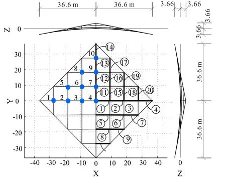
Figure 5: A saddle cable net
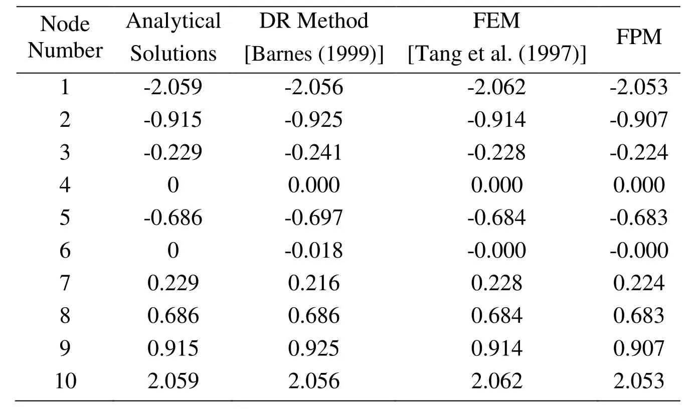
Table 1: Form finding results of direction Z of the saddle cable net
4.1.2 Load analysis of the saddle cable net
Apply distributed load 2 kN/m2to the saddle cable nets.Tension of cables in the Y direction is increased, while tension of cables in the X direction is decreased.However,the whole cable nets are still in tensioned.The results from the FPM are compared with the Nonlinear Finite Element Method, and the accordance can be found, as shown in Fig.6.
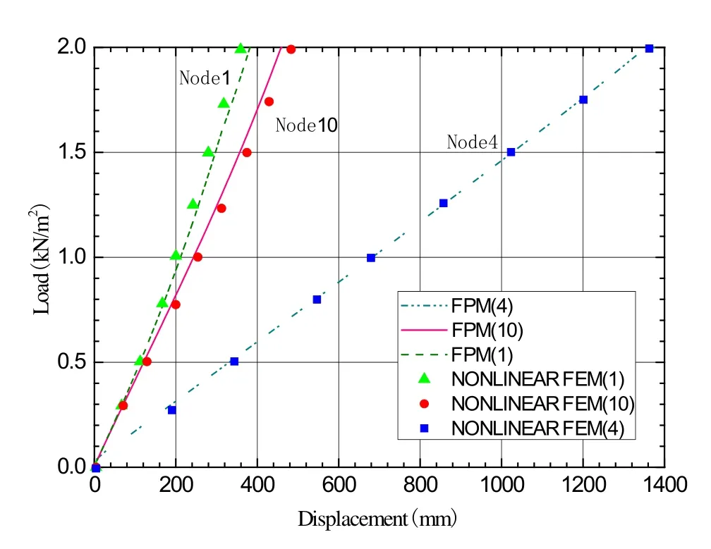
Figure 6: Displacement-load curve on typical node of the saddle cable net
4.1.3 Collapse analysis of the saddle cable net
The material properties of the cable net are Young’s modulusE=1.95×10⁵MPa, yield stressσcrit=1750 MPa, fracture criterionεu=4.5εy, and densityρ=7900 kg/m3.To analysis the collapse process of the structure under random strong wind, the wind speed is set as 40 m/s.The time step is set asΔt=1× 10⁻⁵s.The progressive collapse of the cable nets is shown in Fig.7.The cable near the support first fractured at t=3.50 s.Then, the fracture zone became a ribbon along constraints side.Finally, the middle part of the cable roof was blown away by strong winds.
For the collapse simulation, there are no corresponding results obtained from FEM and DR method.To prove the correctness of present method in collapse simulation, energy analysis is used here.We assume that friction and sound in the fracture do not consume energy in the present analysis.And the energy of the structures under dynamic loads is a conservative system.The external work comes only from the dynamic load.Only damping work, strain energy and kinetic energy are considered as internal work.The formulas for each energy item are as follows:
The kinetic energyWkof the system:

where,miis the mass of particle i; n is the total number of particles.viis the velocity of particle i;dn+1anddn-1are the displacement of the particle at the time step n+1 and n-1,respectively
The elemental strain energyWsof the system:

where,is the elemental stress tensor and the strain tensor, respectively.
The total external workof the system:

where, N is the total time step,is the external force of the particleis the displacement of the particle at the time step of n.
The damping energyWdof the system:

where,ζis the damping factor,
Fig.8 is the energy variations of the cable net under dynamic load obtained from the FPM simulation.As the first fracture happens att=3.50 s, then the strain energy decreases and transforms to kinematic energy.As fracture of more cable occurs, part of the cable net tends to ‘fly away’ from the structure.Since this part is not separated from the structure untilt=4.43 s, it is constrained and subjected a sudden strong constraining force exerted by the supports.Thus, a sudden drop in kinetic energy happens betweent=3.50 s andt=4.43 s.As the dynamic load is removed from the structure after the first fracture happens, and the damping force consumes more and more energy, the kinetic energy tending to zero.Because no gravitational potential energy is considered in the analysis,both the structure connected to the supports and the part separated from the main structure, are in static equilibrium in the air at last.
Fig.8 shows that, the summation of the strain energy, kinetic energy and damping work,is equal to the external work during the whole analysis process, which agrees with the previous assumptions.However, as we know, the conservation of the energy is necessary condition for the proof of the present method, but not sufficient.Mathematical prove will be considered in future work.
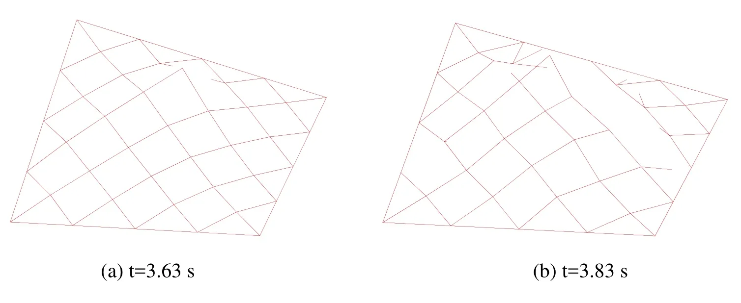
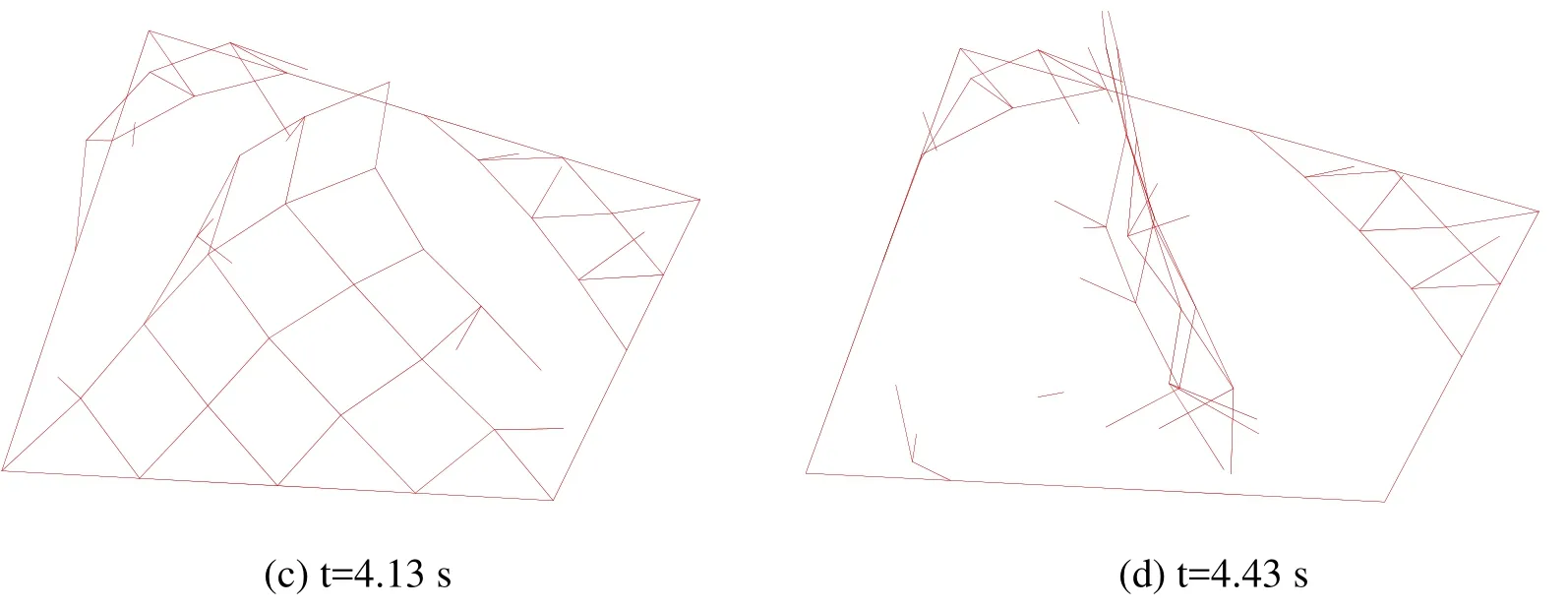
Figure 7: Failure process of the saddle cable net
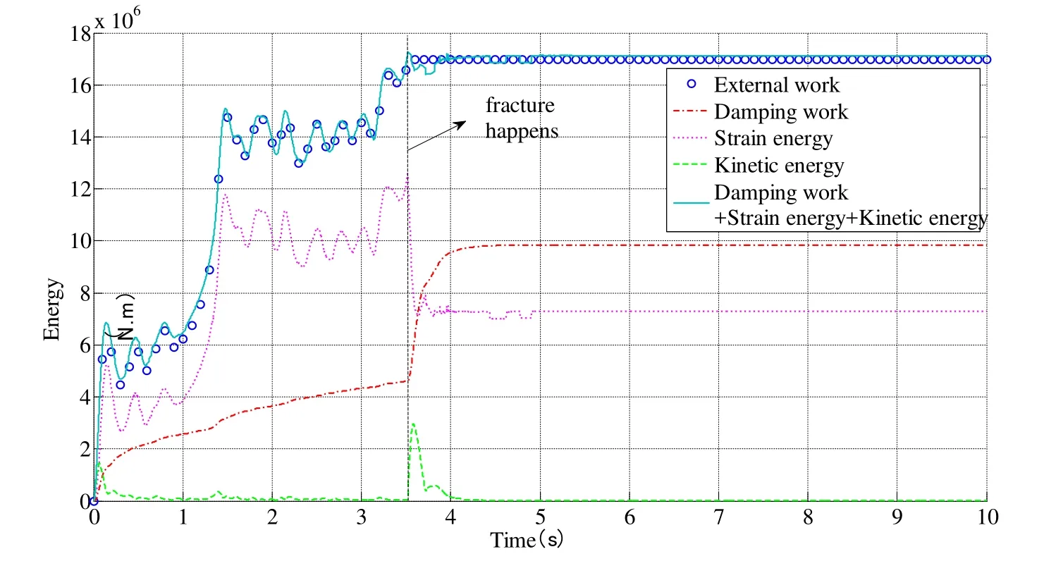
Figure 8: Energy conservation during failure process of the saddle cable net
4.2 A cable net of a stadium
The roof of a sports stadium is composed of two symmetric parts.The Upper edge of the cable net is supported on a parabolic rigid arch.The lower edge is anchored on the elliptical rigid beam.The plane of the rigid arch is vertically divided into the elliptical horizontal plane.The height of the rigid arch is 10 m, the length of the long axis of the ellipse is 88 m and the length of the short axis is 66 m, the grid size of the cable net is 2.2 m×2.2 m.The cross-sectional area of all cables is the same.The stiffness of the cable is EA=4.44×10⁵kN, and the initial prestress is T0=100 kN.The FPM is used for form finding of the cable net roof.Half of the structure is analyzed according to the structural symmetry.The initial geometry of the cable net is shown in Fig.9.The elastic modulus is set as 1/1000 of the true value in the form finding process.The structure geometry after form finding is shown in Fig.10.The prestress of the cable net element is distributed between 100~103.5 kN, which meets the engineering accuracy requirement.Thus, it can be seen that the FPM has good applicability in the form finding of cable net structure.
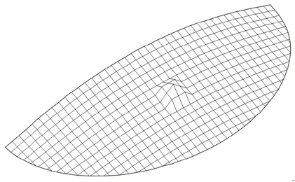
Figure 9: An arbitrary initial geometry of the half of the cable net structure
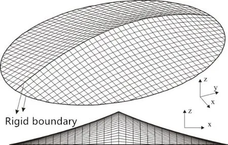
Figure 10: Cable net configurationafter form finding
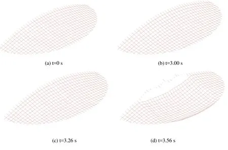
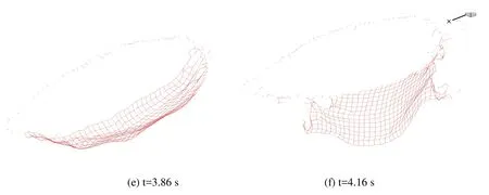
Figure 11: Collapse process of the cable net structure under strong wind
The elastic modulus of the intermediate cable is 1.95×10⁵MPa, the mass density is 7850 kg/m3, the section area is 683.08 mm2, and the dead load is 1.0 kN/m2.In order to investigate the fracture of structures under random wind loads, the wind pressure obtained by AR model is obtained when the average wind speed is 40 m/s.The direction of the wind load is similar to the normal wind suction of a surface in the initial state.The yield limit of cable material is 1750 MPa, the fracture strain is εu=4.5 εy, and the time step is 0.0001 s.The failure process of the cable structure is shown in Fig.11.As can be seen from Fig.11, before the part of the gymnasium is broken, the shape of the surface is in normal deformation state, and the structure is stable and safe.When the fracture occurs,the displacement along the fracture cable becomes very large, and a banded area collapse.Then the fracture zone expands to both sides from the center, and finally all members connected to the center arch are broken, the whole roof collapses and the structure is completely destroyed.
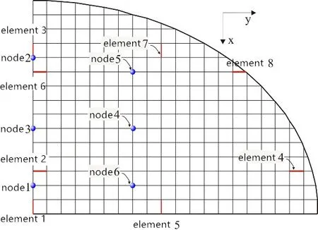
Figure 12: Element and node number of the cable net
The force is removed after fracture happens.Fig.13 is the variations of the internal force of elements shown in Fig.12 in the whole loading process.It is shown that the overall internal force of cables inxdirection is higher than that inydirection.The internal force of cables inxdirection oscillates rapidly and the variations are larger after the fracture.The internal force of cables inydirection undergoes a sudden rise when fracture happens.Then,the internal force also oscillates rapidly.However, the response of cables inydirection lags behind cables inxdirection.The internal force of cable near the support is larger than that of the center part, and the frequency of vibration and reaction is also higher.Fig.14 is the displacement time history of typical nodes in Fig.11.The displacement of the nodes in the middle of the span is larger than that of the nodes near the supports.
Fig.15 is the variation of kinetic energy, strain energy, external force work and damping work in the whole loading time.Because the dead load is one-time loading at the beginning of the analysis, the structure oscillates for a period of time, and the kinetic energy is not zero.However, with the damping effect, the kinetic energy decreases gradually.After fracture occurs, the strain energy of the cable suddenly releases and transforms into kinetic energy, so that the kinetic energy of the structure suddenly increases and then gradually decreases until it stabilizes to zero due to the energy consuming by the damping force.In the whole process, the strain energy, kinetic energy and damping work of the structure are always equal to the external force work, which proves the correctness of the proposed algorithms.
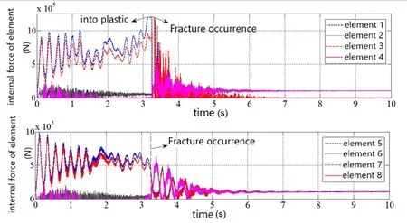
Figure 13: Elemental internal force variations of cable net under strong wind
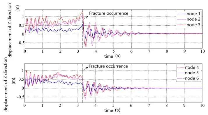
Figure 14: Node displacement variations of cable net under strong wind
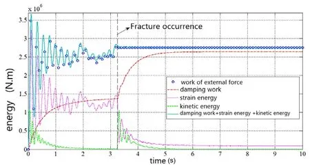
Figure 15: Energy variations of cable net under strong wind
5 Conclusion
The form finding and failure process of cable nets structures under dynamic load is analyzed in this work using the FPM.For the form finding procedure, the FPM seems similar to the traditional DR method.However, the differences in evaluating deformation,force and fracture are significant.No iterations were required in the FPM to resolve the geometric and material nonlinearities.Fracture of members is also efficient handled.According to comparisons with Finite Element method and DR method, the form finding results from the FPM of the cable nets are accurate.The energy analysis of the structural failure process also proves the capability of the FPM in strong nonlinear problem analysis.The mechanisms of the destruction are obtained through the simulation, which provides a reference for the collapse resistance design of this kind of structures.
Acknowledgements:The authors gratefully acknowledge the financial supports provided by the National Key R&D Program of China (2017YFC0806100), Natural Science Foundation of Guangdong, China (2018A030307030), Shantou Science and Technology Program, China (2016-37), Zhejiang provincial transportation department science and technology project (2018-04), and Zhejiang provincial highway administration project(2017-08).
 Computer Modeling In Engineering&Sciences2018年10期
- Computer Modeling In Engineering&Sciences的其它文章
- Increasing Distance Increasing Bits Substitution (IDIBS)Algorithm for Implementation of VTVB Steganography
- Structural Design and Numerical Analysis of a Novel Biodegradable Zinc Alloy Stent
- Improved Teaching-Learning-Based Optimization Algorithm for Modeling NOX Emissions of a Boiler
- A Finite Element Study of the Influence of Graphite Nodule Characteristics on a Subsurface Crack in a Ductile Cast Iron Matrix under a Contact Load
- Numerical Shock Viscosity for Impact Analysis Using ALE Formulation
- Analysis of High-Cr Cast Iron/Low Carbon Steel Wear-resistant Laminated Composite Plate Prepared by Hot-rolled Symmetrical Billet
