A Finite Element Study of the Influence of Graphite Nodule Characteristics on a Subsurface Crack in a Ductile Cast Iron Matrix under a Contact Load
G.Suguinoshita, C.H.Silva and M.A.Luersen,
Abstract: This paper describes a study of the effects of graphite nodule characteristics on a subsurface crack in austempered ductile iron (ADI).A representative specimen of ADI,subjected to sliding contact load, is modeled using finite elements aiming to obtain the shear stress intensity factor (KII).The parameters varied were (i) the nodule diameter(two different values were considered), (ii) the distance between the nodule and the tip of the crack and (iii) the position of the load relative to the tip of the crack.The results of the numerical simulations show that the smaller diameter nodule has a larger influence on KII, suggesting a higher contact fatigue crack propagation rate in the material with the smaller nodule.These results are the opposite of those observed in experimental studies and would appear to indicate that other factors should be also considered to ensure realistic estimates of the contact fatigue strength of ADI.
Keywords: Austempered ductile iron, subsurface crack, stress intensity factor, finite element analysis, graphite nodule.
1 Introduction
Austempered ductile iron (ADI) is a class of cast iron that contains graphite in the form of nodules and an ausferritic matrix.Austempering provides the matrix with high mechanical strength and, at the same time, high ductility.The high fatigue strength and wear resistance of ADI contribute to the competitiveness of this iron, making it suitable for use in mechanical components such as gears, crankshafts and automotive suspension components [Fuller (1985); Stokes, Gao and Reed (2007); Schoenborn, Kaufmann,Sonsino et al.(2006)].ADI also has good machinability compared with steels of equivalent hardness and requires lower heat-treatment temperatures, reducing overall manufacturing costs [Ben Tkaya, Mezlini, El Mansori et al.(2009)].The microstructural changes produced by mechanical treatment (shot peening) of ADI gears have been the subject of several applied studies [Zammit, Abela, Wagner et al.(2013); Fontanari,Benedetti, Girardi et al.(2016); Zammit, Abela, Wagner et al.(2016)].
By controlling the size and dispersion of graphite nodules in the matrix, the mechanical properties of ADI and, consequently, its contact fatigue performance can be modified.Gans et al.[Gans, Guesser, Luersen et al.(2015)] showed that ADI with different nodule sizes, which they called ADI 1 and ADI 2, corresponding to larger and smaller nodules,respectively, had different resistance to pitting wear in an FZG-type test and that in the case of ADI 2 the wear resistance was similar to that of induction hardened AISI 4140 steel.In addition to the nodules, the heat treatment conditions were different, leading, in the case of ADI 2, to a matrix with lower hardness and greater ductility compared to those of ADI 1.Stokes et al.[Stokes, Gao and Reed (2007)] performed fatigue experiments with ADI and showed that the microstructural properties of the matrix,which contains retained austenite and eutectic carbides, have a decisive influence on crack propagation.However, the presence of nodules, in addition to contributing significantly to the nucleation of cracks, also promotes microcracks that propagate from the nodules toward the main crack, potentially reducing its propagation rate [Greno,Otegui and Boeri (1999)].Chapetti [Chapetti (2007)] showed that the fatigue limit of ADI is affected by the “micronotch” effect of the graphite nodules and the relative orientations of the ausferritic microstructure at the boundary.
As they have lower mechanical strength and stiffness than the matrix, ADI graphite nodules behave as discontinuities and, therefore, stress concentrators [Kohout (2001);Zammit, Mhaede, Grech et al.(2012)].As a result, they are susceptible to crack nucleation and influence the fatigue strength of ADI [Li, Zhang, Shen et al.(2017)].In addition, the geometric characteristics of the nodules (their size and distribution) change the stress field in the matrix, modifying the conditions under which cracks propagate.Since the mechanical properties of ADI are influenced by the size and distribution of the graphite nodules, understanding how these factors affect nucleation and propagation of fatigue cracks is essential to improve and make better use of ADI.
Dommarco et al.[Dommarco, Bastias, Dall’O et al.(2008)] sought to understand the influence of the relationship between contact area and projected nodule area on contact fatigue performance.Gans et al.[Gans, Guesser, Luersen et al.(2015)] found that nodule size and inter-nodule distance affect the magnitude and position of the maximum shear stress in subsurface regions of the contact face of gear teeth.Lazzaron et al.[Lazzaron,Luersen and Silva (2017)] proposed a stress concentration factor in the vicinity of graphite nodules near the contact region of gear teeth.They found that changes in nodule size and inter-nodule distance had a great influence on the magnitude of subsurface stresses and observed a stress-relieving effect due to interference from the stress field of neighboring nodules.
Some authors point out that the crack path in ADI is strongly influenced by the characteristic of the ausferritic matrix and the coalescence between macro and microcracks.Lin et al.[Lin and Hung (1996)] showed that the fatigue crack path strongly depends on the location of the next graphite nodule ahead of the crack tip, but in general,the path is perpendicular to the loading direction.Beside this, the crack path between two graphite nodules in ADI is often along the ferrite/austenite interfaces but is also influenced by the orientation of the ferrite laths relative to loading direction.Cisilino et al.[Cisilino, Iturrioz and Ortiz (2002)], using the boundary element method (BEM),demonstrated that the microcracks which start in the graphite nodules propagate toward the main crack, producing a simultaneous crack growth effect leading to a higher propagation velocity of the main crack.This competitive growth of microcracks from the nodules leads to the formation of a bifurcation effect of cracks near the nodules.
Bastias et al.[Bastias, Hahn and Rubin (1989)] used finite element modeling (FEM) to observe changes in the stress intensity factors of a subsurface crack due to changes in its depth and orientation.Using the contact Hertz theory, Komvopoulos et al.[Komvopoulos and Cho (1997)] analyzed the behavior of stress intensity factors in a subsurface crack in a homogeneous medium when the applied load on the surface approaches and moves away from the crack for different friction coefficients.Both studies showed the importance of the mode II stress intensity factor (KII), which is of much greater relevance than the mode I stress intensity factor (KI) in subsurface cracks subject to contact stress.Yang et al.[Yang, Chen and Li (2004)] developed mathematical models based on the Eshelby method to predict KIIfor a long crack interacting with a nearby inclusion and assumed a uniform field stress away from the crack tip.Li et al.[Li, Yang and Li (2014)]also formulated models based on the Eshelby method that considered inclusions near the crack.However, they analyzed KIand compared their results with those obtained by FEM.They found that the presence of inclusions might increase or decrease the stress intensity factor depending on their geometry and position in relation to the crack tip.
To consolidate the results reported in experimental wear tests in the literature, the present study analyzed and compared the stress intensity factor KIIof a preexisting subsurface crack with a nearby graphite nodule in two ADIs with different nodule sizes.
2 Methodology
To simulate the nonconforming contact that arises between a pair of gear teeth, the model developed here was subjected to loading produced by sliding a rigid convex surface of constant radius (here called a “cylinder”) in contact with a plane surface made of ADI.The aim of the modeling was to gain a better understanding of the influence exerted by nodules on subsurface crack propagation and, consequently, the contact fatigue strength of gears.
Finite element analysis was performed with ABAQUS commercial code to build a numerical model.Submodeling [Abaqus (2011); Knight, Ransom, Griffin et al.(1991)],also referred here to as global and local analysis, was used to obtain a more accurate stress distribution in the contact region and reduce computational costs.First, a global model representing the contact between a cylinder and a plane was built and analyzed(neither crack nor nodule were represented in the global model).Next, for each different crack location, nodule size and nodule position, a submodel was created in which the displacements determined from the global model were imposed as boundary conditions.Initially, a two-dimensional standard global model was defined for all the analyses (Fig.1(a)).The dimensions of the cylinder and plane were fixed, and a constant load P of 1 mN was applied at the center of the cylinder.A value of μ=0.5 was used for the friction coefficient μ at the point of contact between the bodies, and a displacement of 1 µm to the right was imposed on the cylinder to introduce the effects of the friction force Fµ, as represented in Fig.1(b).Fig.1(c) shows the local model, which includes the crack and nodule.Fig.2 shows a flowchart of the methodology used.
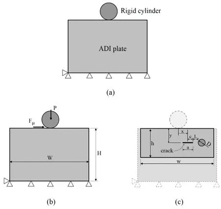
Figure 1: Representation of the contact between cylinder and plate (a), dimensional parameters, loading and boundary conditions for the global model (b) and for the local model (c).Drawings not to scale
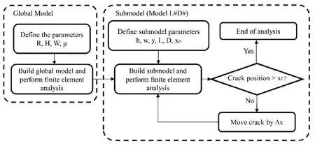
Figure 2: Flowchart of the methodology used
The dimensions of the plate and cylinder were based on those described by Komvopoulos et al.[Komvopoulos and Cho (1997)] and are shown in Tab.1.The dimensions of the local model are shown in Fig.1(c).The values of h, w and y were fixed for all the cases studied and are also shown in Tab.1.The variable dimensions were the position of the crack relative to the load (x), the distance between the nodule and the tip of the crack (L) and the nodule diameter (D), all of which were chosen based on the results of metallographic characterization by Guesser et al.[Guesser, Koda, Martinez et al.(2012)] (Tab.2).

Table 1: Values of the fixed geometric parameters for the global and local models

Table 2: Nodule characteristics in the flank region of the gears [Guesser, Koda, Martinez et al.(2012)]
Because of the high graphite nodularity in both materials, the nodules were considered perfectly circular in the numerical models.To ensure that the ratio of the nodule diameter to the crack length (a=8 μm) was a whole number, we used nodule sizes of 32 μm (4 times the crack length) and 16 μm (twice the crack length) in the numerical simulation.The relevant elastic properties of the matrix and nodules used were those determined by Yan et al.[Yan, Pun and Wua (2011)] and are given in Tab.3.

Table 3: Elastic properties of ADI [Yan, Pun and Wua (2011)]
To represent the movement of the cylinder over the surface of the ADI, x was varied between xo and xf (-12c and 12c, respectively) in 32 constant increments (Δx=3 μm) for each case according to the flowchart in Fig.2.Negative values of x represent the cylinder approaching the crack (right to left), while positive values represent the cylinder moving away from the crack.Sliding is therefore from right to left.This arrangement was chosen to simulate the situation taking place in a crack at the subsurface region of a gear tooth flake, where the load is transmitted progressively from the root to top of one tooth to the next tooth when the teeth come into contact.As the radius of the cylinder is similar to the radius of curvature of the tip of an asperity, we sought to understand the behavior of cracks very close to the contact surface.Mode II stress intensity factors (KII) were determined at each iteration for both tips of the crack.As expected, the mode I stress intensity factors (KI) in the numerical simulations were very close to zero, which suggests the propagation of the crack is mainly due to in-plane shear.Fig.3 shows the nomenclature for the various configurations studied here.

Figure 3: Nomenclature adopted for the various situations studied
Twenty different configurations were analyzed.As one of the tips of the crack is at the edge of the nodule in position L0, only the opposite tip at the other end of the crack was analyzed.The configuration without any nodules was also studied as a reference value(baseline) for the analysis of the other cases.
The finite element mesh was built with six-node triangular quarter-point elements around the tip of the crack and eight-node quadratic elements elsewhere.As quarter-point elements are used specifically to model singularities, such as the tips of cracks, the stresses, strains and stress intensity factors calculated using these elements are more accurate than those obtained with more commonly used elements [Cook, Malkus, Plesha et al.(2002); Anderson (2005)].The finite element mesh was refined around the tips of the crack to form concentric circular rings, as shown in Fig.4, and near the contact region and the edges of the nodules.This yielded a global model with 53,466 nodes, and local models (submodels) with around 35,000 nodes.The refinement technique around the crack tip was based on the work of Nikishkov [Nikishkov (2013)].The cylinder was modeled as a rigid arc, the nodules are considered perfectly bonded to the matrix and the ADI plate was considered to be in a plane strain state.The stress intensity factors obtained in this way were normalized by 2P/πy1/2, and the resulting value was called KII’.

Figure 4: Finite element mesh around the tips of the crack (local model)
3 Numerical results and discussion
As already mentioned, KIwas zero for all the configurations studied, then only the results for the mode II stress intensity factor (KII) are presented and discussed below.
Figs.5 and 6 present KII’(the normalized KII) at each end of the crack as a function of the cylinder position, with the nodule on the left and right of the crack, respectively.
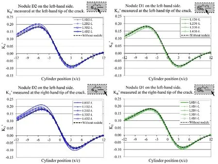
Figure 5: Variation in KII’ at either end of the crack with cylinder position.Nodule to the left of the crack
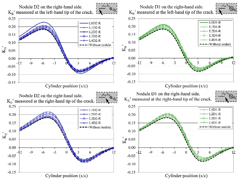
Figure 6: Variation in KII’ at either end of the crack with cylinder position.Nodule to the right of the crack
These figures show that the position of the nodule (on the right or left of the crack and the distance from it to the crack) as well as its size influence the behavior of KII’, which increases or decreases as the cylinder is displaced.The difference, ΔKII’, between the maximum and minimum KII’can be determined from these figures, as shown in Fig.7.ΔKII’represents the amplitude of KII’during a cylinder sliding cycle and may be related to some crack propagation criterion.Fig.8 shows the maximum and minimum KII’for different distances between the nodule and the tip of the crack (L/a).
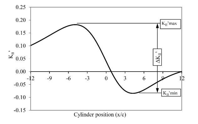
Figure 7: Maximum and minimum KII’ and corresponding amplitude (ΔKII’)

Figure 8: Variation in maximum and minimum KII’ with ratio of crack-to-nodule distance to crack length for each case
As expected, for larger nodule-to-crack distances the KII’maximum and KII’minimum tend to approach the reference values (i.e.when there is no nodule), as shown in Fig.8.In general, KII’maximum increases when a nodule is present, especially when the nodule is to the right of the crack.With the nodule on the left, a reduction in KII’maximum was observed at some distances although this was less significant.
For small distances (L/a<1), a peculiar behavior in KII’maximum was observed.For nodule D2 (the smaller nodule), KII’maximum increases as the distance decreases, but for nodule D1 it reaches a maximum and then decreases, in some cases to below the reference value.Analysis of the shear stress field around the crack reveals that as the distance between nodule D1 and the crack decreases, the stress increases up to a certain distance (L/a equal to 1 or 0.5 depending on the case studied), after which a stress relief effect is observed and the stress reduces.This phenomenon was not observed for the smaller nodule (D2), for which the stress field increases continuously as the nodule-tocrack distance decreases.
Two different behaviors were observed for KII’minimum.When the nodule is on the left,it increases, but when the nodule is on the right, it decreases, especially at a distance L equal to 2a.
Nodule size had a greater influence on KII’minimum than on KII’maximum, and the larger nodule (D1) had the greater influence.Although different sizes, both nodules resulted in similar behavior for KII’minimum in every case.
Fig.9 presents ΔKII’for each case, as well as the percentage difference in relation to the reference (i.e.when there is no nodule).As shown in Fig.7, ΔKII’was calculated as the difference between the maximum and minimum values of ΔKII’during a complete cycle of the cylinder, i.e.as it moves from position x/c=-12 to position x/c=+12.
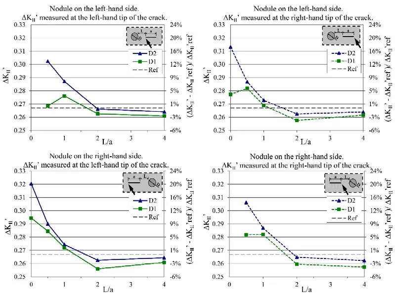
Figure 9: Variation in ΔKII’ with ratio of crack-to-nodule distance to crack length for each case
Fig.9 shows that in each case ΔKII’is lower than the reference value (by up to 4.1%)when the distance between nodule and crack is greater than a certain value (L/a between 1 and 2).For shorter distances, ΔKII’ is greater than the reference value and, regardless of distance, is greater for nodule D2 than for nodule D1.This is particularly evident for short distances: With the nodule on the right-hand side of the crack, ΔKII’measured at the left-hand end of the crack increased by 20.1% with nodule D2, while the greatest increase with nodule D1 was only 10.7% (nodule on the right-hand side of the crack and ΔKII’measured at the left-hand end of the crack).
4 Concluding remarks
The presence of a nodule with a lower stiffness than the base material near a subsurface crack subjected to contact loading influences the behavior of the stress intensity factor.This behavior was investigated by analyzing KIIat the tips of the crack and was shown to be a result of several factors together.For the loading and boundary conditions considered in this study, KIIcan increase or decrease when a nodule is introduced depending on the position of the load, the size and position of the nodule and its orientation in relation to the direction of sliding (to the right or left).
Both the nodule sizes studied here had a significant influence on the behavior of the crack.For values of L/a below 2, ΔKII’was higher for both nodules than without a nodule.Therefore, it can be inferred that crack propagation is more intense when there is a nodule near the crack.However, for larger values of L/a, ΔKII’was below the reference value,and a nodule in these positions can therefore be expected to help reduce crack growth.
Smaller-diameter nodules resulted in higher values of ΔKII’than larger nodules,indicating that for the contact loads considered in this study a crack in a matrix with D2-sized nodules (i.e.nodules with a smaller diameter) tends to propagate faster than a crack in a matrix with larger (D1-sized) nodules.
As higher crack propagation rates suggest higher wear rates, the results indicate behavior that is the opposite to that observed in experimental tests, in which ADI 1 (which has nodules with a larger average diameter) had higher wear rates in an FZG-type test than ADI 2 (which has nodules with a smaller average diameter).
Crack propagation rate is therefore not the main factor determining the superior wear resistance of ADI 2, but rather other factors, such as crack arrest or retardation of crack propagation when a crack reaches a node and a lesser tendency for crack initiation.Gans et al.[Gans, Guesser, Luersen et al.(2015)] also showed that stress concentration in nodules is not a major factor in the crack propagation stage.Other characteristics of ADI,such as their ability to delay the fracture stage when the tip of a crack reaches a new nodule and the reduction in crack propagation rate due to the crack branching mechanism[Greno, Otegui and Boeri (1999)], should therefore be considered in the analysis to determine what causes this performance difference in wear situations.
Finally, it should be highlighted that this study considered individual nodules and cracks under specific loading conditions.To extend the results, different model geometries and boundary conditions could usefully be considered together with multiple nodules so that the influence of neighboring nodules on the adjacent stress fields could be determined.In addition, the interface conditions between nodule and matrix could be modeled more accurately rather than as a perfect bond.
Acknowledgement:The authors would like to express their thanks to the Brazilian funding agencies CAPES and CNPq.
 Computer Modeling In Engineering&Sciences2018年10期
- Computer Modeling In Engineering&Sciences的其它文章
- Increasing Distance Increasing Bits Substitution (IDIBS)Algorithm for Implementation of VTVB Steganography
- Structural Design and Numerical Analysis of a Novel Biodegradable Zinc Alloy Stent
- Improved Teaching-Learning-Based Optimization Algorithm for Modeling NOX Emissions of a Boiler
- Form Finding and Collapse Analysis of Cable Nets Under Dynamic Loads Based on Finite Particle Method
- Numerical Shock Viscosity for Impact Analysis Using ALE Formulation
- Analysis of High-Cr Cast Iron/Low Carbon Steel Wear-resistant Laminated Composite Plate Prepared by Hot-rolled Symmetrical Billet
