Structural Design and Numerical Analysis of a Novel Biodegradable Zinc Alloy Stent
Kun Peng, Aike Qiao, *, Makoto Ohta, Narendra Kurnia Putra, Xinyang Cui,Yongliang Mu and Hitomi Anzai
Abstract: Biodegradable zinc alloy stents are a prospective solution for complications caused by the incompatibility between artery and permanent stents.However, insufficient scaffolding has limited the clinical application of biodegradable zinc alloy stents.Therefore, in this study, a new stent concept was designed to improve the scaffolding.The mechanical performances of the new and a traditional design stent were investigated and compared using finite element analysis (FEA).The new and traditional design stent were expanded to the intended radial displacement of 0.24 mm under the expansion pressure of 0.58 MPa and 0.45 MPa, respectively.Then, a pressure load of 0.35 MPa was exerted on the outer surfaces of the two stents to compress them.The results showed that the radial recoiling ratio were 45.3% and 83.3% for the new and the traditional stent,respectively.The simulations demonstrate that the biodegradable zinc alloy stent offers enhanced support because of the new structural design.This study implies that biodegradable zinc alloy stent can be a new competitive intervention device for the future clinical cardiovascular application.
Keywords: Biodegradable stent, design, finite element analysis.
1 Introduction
Recent technological progress in biodegradable stents [Hermawan, Dubé and Mantovani(2010)] has led to several advancements in the field of cardiovascular intervention.Unlike a permanent stent, a biodegradable stent provides only a temporary opening into the stenotic artery.After it has successfully reshaped the artery, a biodegradable stent can degrade gradually and is ultimately absorbed by the human body [Waksman (2007)].Biodegradable stents can avoid risks such as in-stent restenosis [Mitra and Agrawal(2006)], late thrombosis [Hoffmann, Mintz, Dussaillant et al.(1996)], hypersensitivity reactions [Virmani, Guagliumi, Farb et al.(2004); Kö ster, Vieluf, Kiehn et al.(2000)],and long-term therapies [Waksman (2006)] resulting from the biological incompatibility between vessel and permanent stent.However, due to sever lumen loss after implantation,the biodegradable stent has not been widely applied for clinical surgery yet.Abbott company (Santa Clara, CA, USA) marketed the Absorb GT1 BVSTMas an everolimus-eluting stent fabricated from the most-advanced, fully absorbable polymer[Karanasiou, Papafaklis, Conway et al.(2017)] however, the sale of that stent was halted in 2017 mainly because the Young’s modulus and strength of biodegradable material were far less than those of the materials used in permanent stents.To address these challenges, structural innovations of biodegradable stent can be applied to improve the scaffolding of stent [Di, Griffiths, Goktekin et al.(2004)].
However, novel structures of biodegradable stent that provide adequate support for arteries have not been reported yet.Several supposedly new designs are merely optimizations of the traditional stent design.For example, Li et al.[Li, Wang, Wei et al.(2017)] used a surrogate Kriging model to optimize the stent geometry and improve mechanical performance.However, this is a difficult task in simulation because it requires repetitive modeling and meshing procedures and solving convergence problems.Thus, Wu et al.[Wu, Petrini, Gastaldi et al.(2010)] optimized the structure with 2D simulations using an automated evolution process.The optimized stent enhanced scaffolding performance by 24% compared with an existing magnesium alloy stent design.Similarly, Li et al.[Li, Zheng, Qiu et al.(2014)] optimized the geometry of the struts by gradually varying their width and introduced annealing technology to decrease the radial stress and improve the scaffolding behavior.Furthermore, Grogan et al.[Grogan, Leen and McHugh (2013)] developed a method for simulating corrosion of stent.Based on that simulation technology, the relations between stent structure and scaffolding performance over the service time of the stent were studied and the stent structure was optimized for durability.The results predicted that the service time of an optimized biodegradable magnesium stent is ~1.5 times longer than a commercially available design.In recent years, biodegradable zinc alloy stent has attracted the attention of related studies because of its outstanding metallic and biologic properties, and it may become the delegate of new generation stent.
In summary, most studies have focused on improving mechanical performance with various optimizations of traditional stent designs.However, the improvements of the optimized stents are limited because of the conflicts among the mechanical performance.Only a truly innovative design can dramatically enhance the scaffolding behavior of the stent.
Therefore, in this study, a novel structure was designed to enhance the scaffolding capability of biodegradable zinc alloy stents.A traditionally designed stent was studied as an experimental control.The structural support offered by these two stents were investigated and compared via FEA.
2 Structure design
As shown in Fig.1(a), the new stent design incorporates three components: (1) Struts that keep the vessel open after the stent expansion, (2) Links that connect the struts, and (3)Two semicircular strutting rings inserted through the links.Similar to the traditional stent design as shown in Fig.1(b), two sinusoidal struts are connected by straight links and each strut comprises six sinusoidal peaks.The width and thickness of the struts and links are both fixed at 0.17 mm.The lengths of the struts and links are kept constant at 1.7 mm and 0.4 mm, respectively, and the outer diameter when crimped is 2.4 mm.
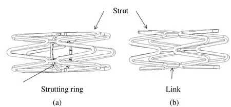
Figure 1: Structures of biodegradable zinc alloy stents.New design; (b) Traditional design
Inspired by the ratchet and pawl, which moves in one-way, the highlight of the new design is two semicircular strutting rings that are inserted through the links, as shown in Fig.2; the gray and white parts represent the links and strutting rings, respectively.Two semicircular strutting rings are connected to a symmetrical pair of solid links and run through other links that have trapezoidal holes.
Fig.3 illustrates the function of this design.As seen in Fig.3(a), the strutting ring comprises the wedge parts and the connecting parts.Figs.3(b)-3(f) show that as the strutting ring moves from left to right, the wedge part is bent down due to compression by the link.The strutting ring cannot move backward because of the interaction between the wedge part and the link, as shown in Fig.3(f).Because of this feature, the strutting rings allow the stent to expand but not to contract.Thus, the new stent design can provide sufficient support for opening an artery.The dimensions of the strutting rings and links are shown in Fig.4.

Figure 3: Interaction between the strutting ring and link.(a) Design of the strutting ring;(b) Initial status of the strutting ring and link; (c) The wedge part is compressed through the link; (d) The wedge part recoils after through the link; (e) The interaction between the wedge part and link
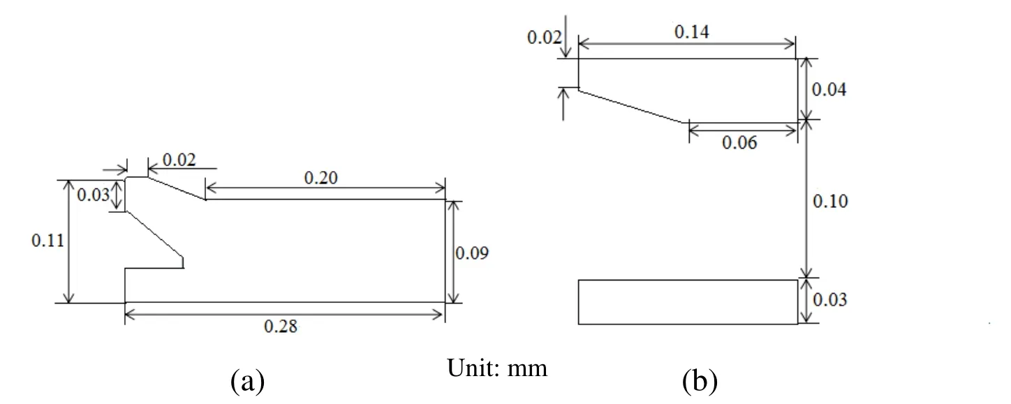
Figure 4: Dimensions of the strutting ring and link (a) Dimensions of the strutting ring;(b) Dimensions of the link
In the process of manufacture, the basic structure (including the struts and the links) and the strutting-rings are fabricated by laser cutting metal tubes.Subsequently, the basic structure is crimped and the strutting rings are inserted into the basic structure.The new stent is implanted into stenotic vessel through catheter system.
3 Materials and methods
3.1 Material
Biodegradable zinc alloy was used for the modeled stent, which is a commonly used elastic-plastic material with nonlinear behavior.The stress-strain curve in Fig.5 plots tensile test data for this material obtained from the Institute of Metallurgical Research,Northeastern University, China.The Young’s modulus (E) is set to 74.3 GPa, Poisson’s ratio (v) is 0.3, and the ultimate yield stress is 325 MPa.
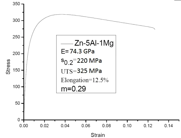
Figure 5: Stress-strain curve
3.2 Geometrical model and meshing
As is shown in Fig.1, the traditional stent design composed of struts and links was studied as a control group to reveal the effect of the strutting rings of the new stent on scaffolding performance.The dimensions of the traditional stent design were fixed arbitrarily to be equal to those of the new stent.As shown in Fig.6, one quarter of the model was built for FEA due to the symmetry of the design.
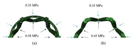
Figure 6: FEA models.(a) New stent design; (b) Traditional stent design
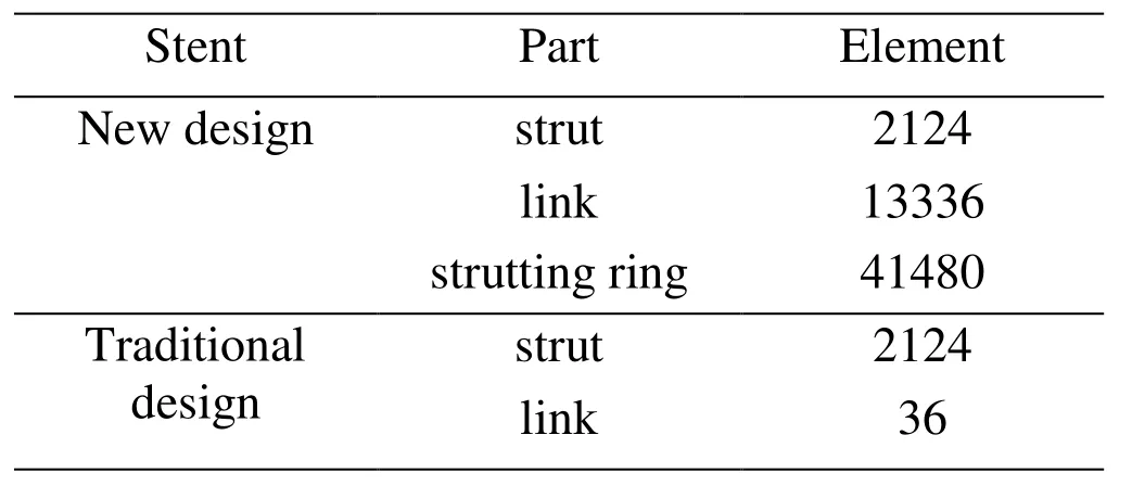
Table 1: The number of elements
The two geometrical models were meshed with hexahedral elements (C3D8R, reduce integration) and pentahedral elements (C3D6R, reduce integration) using Hypermesh 13.0 (Altair, USA).Different element sizes are chosen depending on the parts (strut, link,and strutting ring).The number of elements used to mesh the different parts is listed in Tab.1.The mesh sensitivity was tested via decreasing various different elements size by five times and the results differed less than 5% to each other.
3.3 Boundary conditions and loading
The two simulations were performed using ABAQUS/Explicit 6.13 (ABAQUS Inc.,USA), a commercially available FEA solver.Symmetric constraints were imposed on the corresponding symmetry nodes of the stent models.The intended radial expansion displacement is 0.24 mm.Due to complex structure of the new stent and expansion resistance resulting from interaction between the strutting-rings and the links, expansion pressure at the value of 0.58 MPa was applied for the new stent while 0.45 MPa for the traditional stent.Both loads were imposed on the inner surface of the new stent and the traditional stent during the expansion (0-0.0020 s) and fell to zero (deflated) as shown in Fig.7(a).Then, a pressure of 0.35 MPa was gradually exerted on the outer surfaces of the two stents during the recoiling (0.0020-0.0050 s) as shown in Fig.7(b).This pressure represents the compression caused by the vessel and plaque.
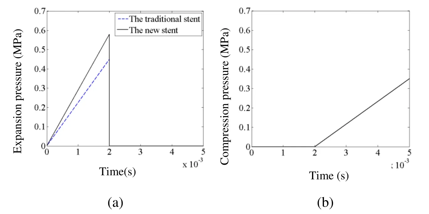
Figure 7: Loading of the two stents.(a) The expansion pressure over time; (b) The compression pressure over time
4 Results
The radial recoiling ratio is defined as follow:

Fig.8 depicts the distribution of von Mises stress in the new stent at four different instants: Time a=0.0007 s, time b=0.0020 s, time c=0.0030 s, time d=0.0050 s.Fig.8(a)represents the von Mises stress distribution in the new stent at time a.At this instant, the new stent has expanded 0.03 mm in the radial direction.Two wedge parts (elements “A”and “B” in Fig.8(a)) have been pulled into the links.Because they are pulled and compressed, the connecting parts A1and B1show the maximum von Mises stress.The maximum von Mises stress is located at the connecting part C1for the same reason, as shown in Fig.8(b).At time b, the new stent expands to the intended radial displacement(0.24 mm) with the maximum expansion pressure.As shown in Figs.8(a)-8(b), the strutting ring gradually slides through the links.Wedges A and B are compressed through the links and recoil during this period, which explains the residual stress that appears in wedges A and B.Then, Figs.8(c)-8(d) show the contraction of the new stent design.As illustrated in Fig.8(c) (time c), wedge A contacts the link due the recoiling of the new stent.Then, Fig.8(d) (time d) illustrates the final von Mises stress distribution in the new stent.The maximum von Mises stress in the new stent is 324.9 MPa, and the stress is concentrated on the position at which the strutting ring and the link meet.Recoiling is prevented in the new stent owing to this interaction.Consequently, the FEA results suggest that the new stent will function well during the whole deployment process, as the design intends.
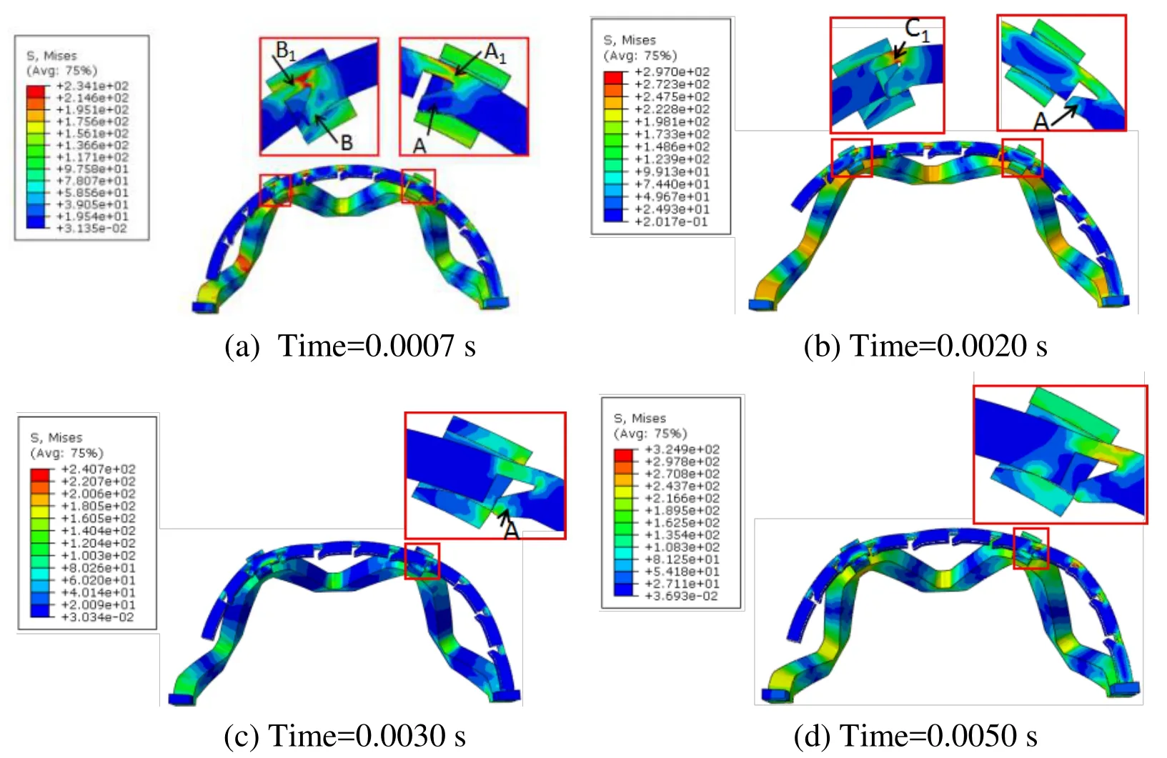
Figure 8: The von Mises stress distribution in the new stent during implantation (a)Wedges A and B are compressed into the link; (b) The new stent expands to the intended displacement; (c) With the new stent recoiling, the wedge A contacts the link; (d) The interaction between the wedge A and the link prevents the new stent from recoiling
Fig.9 plots the radial displacement over time of the new stent during the deployment process.The four important times (time a, b, c, d) are marked in Fig.9.Expansion occurs in two stages.Before time a, the new stent deforms elastically.Wedges A and B are compressed into the links from time a to 0.0010 s (Fig.8(a)), which causes a large resistance to expansion.The rate of expansion is therefore negative during this period.After 0.0010 s, the new stent design deforms plasticity and expands steadily.At time b,the new stent design expands to the maximum radial displacement, at the value of 0.24 mm.From time b to c, the radial displacement decreases drastically because of elastic recoiling and the loading exerted on the outer surface which represents the compression from the artery.However, the displacement decreases gently after time c because wedge A contacts the link, as shown in Fig.8(c).At time d, the radial displacement decrease to 0.13 mm, the final radial displacement of the new stent.
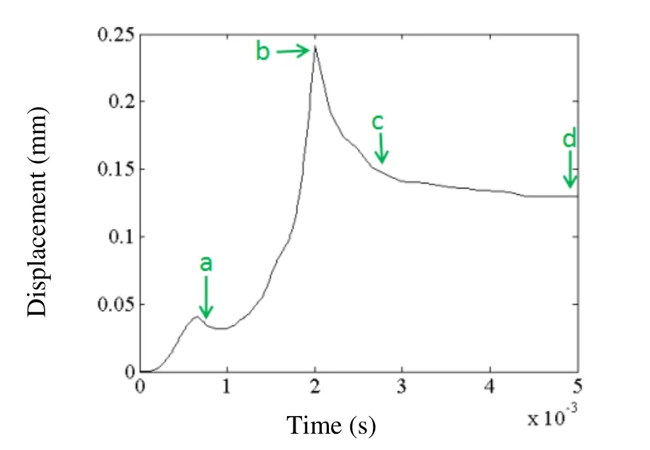
Figure 9: Radial displacement of the new stent.The points a, b, c, and d represent the four times described in Fig.8
The radial displacements of the new stent and the traditional stent are plotted in Fig.10.The displacement of the traditional stent decreases more quickly than it of the new stent during the initial contraction stage (time b-0.0023 s).This difference emerges because friction between the strutting ring and the links resists the recoiling of the new stent.This also explains the concentration of stress at the edge of the strutting ring in Figs.8(c) and 8(d).The specific results are listed in Tab.2 for comparison.
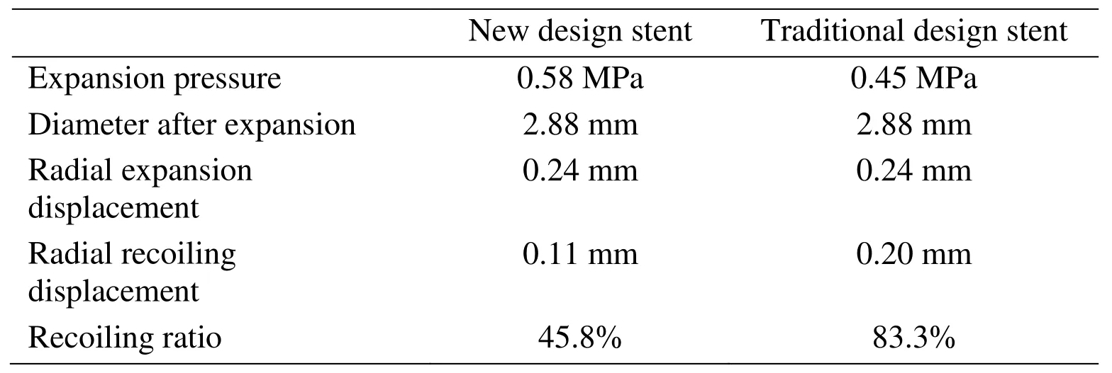
Table 2: Simulation results of geometry change for the two types of stent
As can be seen in Tab.2, both the new stent and the traditional stent expand to the intended diameter.The recoiling displacements are 0.11 mm and 0.20 mm for the new stent and the traditional stent, respectively.Thus, the radial recoiling ratios are 45.8% and 83% for the new stent and the traditional stent, respectively.A notable 45.0% decrease of radial recoiling ratio is found in the new stent.This suggests that the new stent can provide stronger support for remodeling of an artery, which is of significance for clinical applications.
Biodegradable material has lower elastic modulus (25% of SS), resulting in the need of more material (widening stent strut) to provide adequate scaffolding [Karanasiou,Papafaklis, Conway, et al.(2017)].Extremely high stress concentration in struts is induced by more material after expansion.Therefore, it is necessary to evaluate von Mises stress distribution for the percent volume of strut.A histogram of the von Mises stress distribution for percent volume of strut is shown in Fig.11.The von Mises stress distribution in the strut of the new stent is similar to that of the traditional stent.Only 3% and 6% of the strut of the new and traditional stent suffer 300-350 MPa of von Mises stress, which suggest that the scaffolding capability of the new stent is improved owing to the structural innovation rather than excessive plastic deformation.
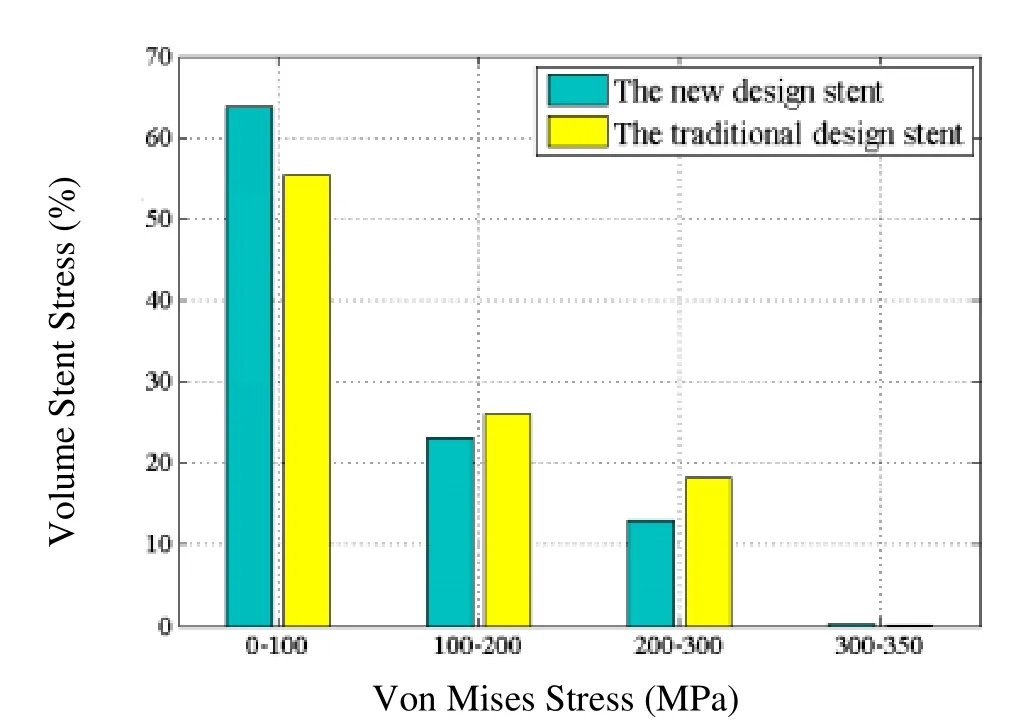
Figure 11: Von Mises stress distribution for the percent volume of strut
5 Discussion
Compared with the traditional stent, the radial recoiling ratio of the new stent was decreased 45%.This improvement of the scaffolding performance clearly exceeds that reported previously [Wu, Petrini, Gastaldi et al.(2010)].The new stent can provide adequate scaffolding for stenotic vessel to avoid severe lumen loss at the initial period of deployment.With the degradation of the new stent, the mechanical performance of the strutting-ring will be changed which means the strutting-ring will be weaken structurally and functionally.This feature achieves the profile of an ideal biodegradable stent[Hermawan, Dubé and Mantovani (2010)].An ideal biodegradable stent is supposed to provide strong scaffolding for remodeling diseased vessel at the initial period of therapy(6-12 months) and break down once the revascularization is finished.
Both the struts and links of the new stent design are the basic geometrical elements of the common structure, and their dimensions are designed with reference to the size of existing biodegradable stents reported in the literature [Li, Zheng, Qiu et al.(2014);Gomes, Puga, Alves et al.(2017)].To be expanded to the intended displacement,pressure at value of 0.58 MPa and 0.45 MPa were exerted on the inner surface of the new stent and the traditional stent respectively.Due to the complex structure of the new stent,especially interaction between the strutting-rings and the links, expansion pressure of the new stent should be higher than the traditional stent.The pressure of 0.58 MPa approximates the expansion pressure of other biodegradable stent [Wu, Petrini, Gastaldi et al.(2010); Debusschere, Segers, Dubruel et al.(2015)].Thus, the new stent will not require any new equipment for deployment.
The von Mises stress distribution shows that the von Mises stress is concentrated at the curved parts of the struts [Debusschere, Segers, Dubruel et al.(2015)] and wherein the strutting rings and the links meet.The maximum von Mises stress of 324.9 MPa is not over the yield stress of zinc alloy.In this study, a pressure of 0.35 MPa which is a little higher than compression pressure from general plaque-vessel system is applied on the outer surface of the new stent to access its scaffolding performance.Thus the maximum stress in the new stent will be lower than 324.9 MPa and the damage caused by the stress concentration will be decrease, if the new stent is deployed into plaque-vessel system.For some special plaque such as calcified plaque, the compression pressure from the special plaque is over 0.35 MPa.To address this problem, on the one hand, optimization is going to be performed to decrease the maximum stress in the new stent in future work,on the other hand, some technology such as predilation and rotablation can be applied to assist interventional therapy.
As shown in Fig.2, the strutting rings are designed to pass through the links along the circumferential direction and the inner and outer surfaces do not extend beyond the inner and outer surfaces of the links.Thus, the adhesion of the new stent after implantation is as well as it of the traditional stent.
In the loading discussed above, a pressure load of 0.35 MPa is applied on the outer surface to represent the compression from the vessel and plaque.However, the real artery has more complexity such as artery tortuosity [Li, Liu, Li et al.(2017)], the composite of plaque [Conway, McGarry, Edelman et al.(2017)].Therefore, in future studies, the numerical simulation of the deployment of the new stent deployed into stenotic vessel will be performed and the mechanical performance of the new stent and hemodynamics[Qiao and Liu (2008)] will be investigated.In addition, structural damage detection of the new stent following degradation will be investigated using existing method [Xu, Ding, Lu et al.(2015)].
6 Conclusion
A novel structure for stents fabricated from biodegradable zinc alloy with strong scaffolding performance was proposed.The mechanical performances including stress distribution, expansion pressure, and recoiling were tested via FEA approach.The analysis results suggest that the new stent could provide much stronger scaffolding than a traditional stent because of the novel structural design.This study implies that biodegradable zinc alloy stent can be a new competitive intervention device for the future clinical cardiovascular application.
Acknowledgement:This study was supported by Major Project of Science and Technology of Beijing Municipal Education Commission and Type B Project of Beijing Natural Science Foundation (KZ201710005007).Part of the study was performed under the General Collaborative Research Project of the Institute of Fluid Science, Tohoku University (J17I105).
 Computer Modeling In Engineering&Sciences2018年10期
- Computer Modeling In Engineering&Sciences的其它文章
- Increasing Distance Increasing Bits Substitution (IDIBS)Algorithm for Implementation of VTVB Steganography
- Improved Teaching-Learning-Based Optimization Algorithm for Modeling NOX Emissions of a Boiler
- A Finite Element Study of the Influence of Graphite Nodule Characteristics on a Subsurface Crack in a Ductile Cast Iron Matrix under a Contact Load
- Form Finding and Collapse Analysis of Cable Nets Under Dynamic Loads Based on Finite Particle Method
- Numerical Shock Viscosity for Impact Analysis Using ALE Formulation
- Analysis of High-Cr Cast Iron/Low Carbon Steel Wear-resistant Laminated Composite Plate Prepared by Hot-rolled Symmetrical Billet
