
Numerical study of cavitating flow in orifices and its effect on spray characteristics *
2018-10-27 09:11MortezaGhorbani
水动力学研究与进展 B辑 2018年5期
Morteza Ghorbani
1. Mechatronics Engineering Program, Faculty of Engineering and Natural Science, Sabanci University,Istanbul, Turkey
2. Department of Biomedical Engineering and Health Systems, KTH Royal Institute of Technology, Stockholm,Sweden
Abstract: The bubbly flow regime inside orifices has significant effects on several applications, and studying its trend along an orifice could be helpful in identifying the flow mechanism in various situations.The flow regime inside an orifice depends on the situation which has been specified for the orifice.Orifice geometry has a considerable effect on bubbly flow in injectors.Meanwhile, spray characteristics are influenced by the fuel flow inside an orifice, which has strong effects on the mixture of fuel-air.In this study, spray characteristics are studied for different values of the orifice angle.The cavitation phenomenon which occurs inside an orifice varies in intensity and patterns at different angles of the orifice and consequently has diverse effects on spray characteristics.The governing equations are solved by the SIMPLE algorithm.The spray flow is modeled by the discrete droplet method (DDM), the droplet breakup is modeled by the WAVE model, and the primary breakup is modeled by the DIESEL BREAK UP model.In order to generate cavitation phenomenon inside orifices and investigate its effect on spray characteristics, the angle of orifice with respect to the injector body is varied and the problem is studied for different angles of orifice.
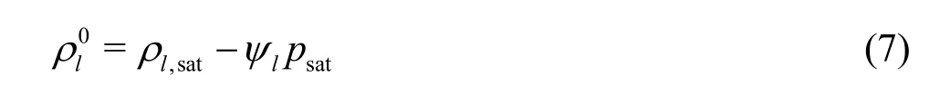
Key words: Cavitation, iinjector angle, microchannel, spray
Introduction
A cavitation nucleus is considered to be a crucial reason for a lack of liquid tension.Gas bubbles, gas in slots and various types of boiling and condensation are the simple examples of the existence of nuclei.The fluid operated in fluid machinery devices is affected by the cavitation phenomenon, and bubbles with different sizes are created at various liquid tensions[1-3].The nature of the bubbles strongly depending upon ambient, discharge and upstream pressures[4-6].
The improvement of fuel injection systems is an important way of decreasing NOxand other undesired emissions.Therefore, the development of effective techniques to improve fuel injection systems to decrease undesired emissions is very important.It is known that the fuel flow regime inside an injector affects spray characteristics.Understanding the physics of the fuel flow inside an orifice and its effects on the characteristics of spray can help researchers find techniques for decreasing emissions.The fuel flow inside nozzles is unsteady, and the injection duration is very short.Therefore, numerical studies might be more appropriate than experimental investigations due to the very small dimensions of nozzles and unsteady nature of the fuel flow inside orifices.On the other hand, spray has an important effect on outlet emissions, and the presence of small droplets in spray leads to better combustion and consequently better performance and torque[7].
The flow inside an orifice enters with high velocity toward the combustion chamber, which forms a fuel spray, and the droplets in the spray can evaporate.Experimental investigations show that the cavitation phenomenon occurs in orifices and strongly affects the spray characteristics and the primary breakup.The cavitation phenomenon occurs in an orifice when the static pressure drops to saturated vapor pressure.Therefore, the geometry of orifices and the resulting pressure drop are the most important parameters determining the occurrence of the cavitation phenomenon.Schugger and Renz[8]performed experimental studies on nozzles with different inlet geometries and showed that sharp inlet edges cause powerful cavitation.Experimental studies show that Cavitation and Reynolds numbers are the two most important factors in creating a flow which contains cavitation.As the Reynolds number increases, the Cavitation number, which was introduced by Nurick[9],will decrease.The boundary layer in an orifice tends to separate from the wall in the entrance of the orifice due to sudden variation in the flow direction, which causes the creation of “Vena Contracta”.Due to separation in the entrance of the nozzle, a rotating area is created between the orifice and the vena contracta,and the cavitation phenomenon occurs in this region[10-14].
Hydrodynamic cavitation has recently been studied in microfluidic systems by Mishra and Peles[15-16]with length scales between 10 μm and 200 μm.The pernicious effects of cavitation have been a cause for concern in the design of macro world hydraulic equipment[2,17], and countless experimental and modeling studies have been archived in the scientific literature.
Spray penetration analysis was carried out by Nbar and Siebers[18]in 1996.They showed that the spray region can be divided into two sections namely primary and secondary breakups.Nishimura and Assanis[19]studied a model for the primary breakup by using the energy released from the collapse of cavitation bubbles.They used the fluid dynamics code KIVA-3V and showed that the energy of the cavitation collapse can be used to predict the spray cone angle.The collapse of cavitation bubbles within the liquid fuel in the core of the spray during the primary breakup results in small droplets in the spray.Their numerical results were consistent with experimental results for non-evaporated sprays, particularly for penetration length, spray cone angle and SMD.Payri et al.[20]studied the effects of nozzle geometry on spray characteristics through the examination of spray momentum flux.They examined the mass flux and momentum flux for both cylindrical and conical orifices and found that the injection and the discharge pressures are important parameters for the occurrence of the cavitation phenomenon inside orifices.Sou et al.[21]investigated cavitation effects on liquid jet atomization.They studied the effects of cavitation and Reynolds numbers on the occurrence of cavitation inside the nozzle and liquid jet for different values of flow rate.They showed that the collapse of cavitation bubbles is the most important reason for ligament formation.
The effect of the orifice geometry and the primary breakup on the spray has been considered in the literature in recent years.Suh and Lee[22]showed that cavitation is created for different values of the ratio of length to diameter of the orifice when the discharge coefficient has a certain magnitude.Lower values of the ratio of length to diameter of the orifice lead to an extended spray and a better breakup.Payri et al.[23]studied the effect of diesel nozzle geometry on liquid spray penetration length in the evaporated condition.They used 3 sac hole nozzles which have 6 holes with different cone angles.They finally suggested a suitable model for the penetration length of the liquid jet on the base of flow conditions.This model has clarified the relation between nozzle geometry and liquid length before the primary breakup to some extent.Som and Aggarwal[24]investigated the effect of the primary breakup on spray characteristics and combustion.They employed a numerical-physical model on the basis of a Eulerian-Lagrangian approach for two phase flow and described the dynamic behavior of the vapor phase with Navier-Stokes equations which are linked to RNGk-εturbulence model.The time and length of spray atomization are too short, therefore, they used the Sub-grid scale model to describe the spray physics, and finally, the CONVERGE code was used for simulation.The effect of the injection pressure on cavitation which occurs in the orifice of the diesel injector is also considered by Wang and Su[25].They illustrated an interesting unsteady treatment of slight cavitation and super cavitation occurrence due to injection pressure pulses.They reported that the details of the relation between injection pressure and the unsteady cavitation phenomenon in the injector are still unclear.
In the current study, the cavitating flow regime for various values of orifice angles was studied, the trends of the bubbly flow regime were modeled in different situations, and spray properties have been studied to investigate the effect of cavitation occurrence for different values of the orifice angles with respect to the injector body.The cavitation phenomenon occurs inside the orifice, where the static pressure drops to a value of less than the saturated vapor pressure.The results of this work show that in the case with 130 680 cells, the grid independency of the numerical model is obtained, and it exactly corresponds to the aspect ratio of one for the cubic cells of the discretized domain of the problem.Furthermore, the validation of the numerical modeling of the problem has been acquired by comparison of the numerical results of this paper and the experimental and numerical results.
1.Physical and numerical modeling
Injector performance has a significant effect on engine efficiency.Therefore, a deep understanding of fuel spray behavior under different circumstances is very important.The primary breakup is one of the important mechanisms that affects the spray state.The mechanisms of liquid break have not been specified clearly yet, since the size of the droplets near the outlet of the orifice is still unknown.Moreover,atomization close to orifices is not known due to the astonished state of the spray.There are many droplets in some regions of the spray, so identification of the breakup details is difficult.Thus, experimental measurements and spray analysis are complicated.The role of the primary breakup model is to specify the initial conditions of the droplets such as initial radius and initial velocity, which can be determined by the state of the orifice flow.
1.1 The cavitation modeling
Barotropic equation of state is used to calculate the development of cavitation
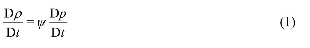
whereψis the compressibility of the mixture and defines as below
The barotropic equation of state is used when there is pure liquid or pure vapor, and when there is a mixture of liquid and vapor a linear equation of state is used for both phases:
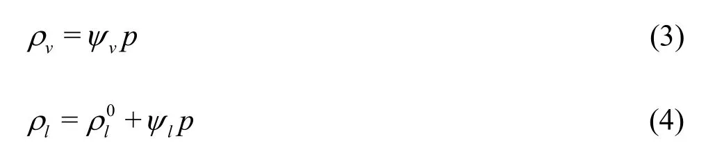
where
When there is no cavitation,γis equal to zero,whereasγis equal to one for fully cavitating flow in the fluid.Therefore, the equilibrium equation of state of the mixture is defined as below
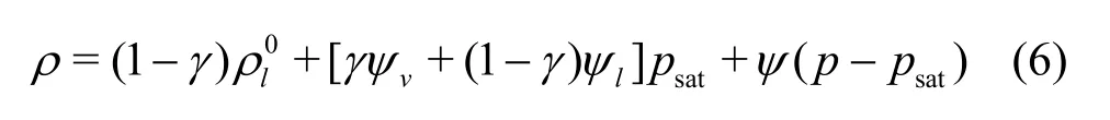
where
Consequently, the compressibility of the mixture is modeled by a simple linear model as follows

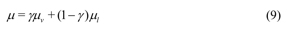
The viscosity of the mixture is known by employing the following linear model
1.2 The spray modeling
The conservation equations are solved for both the liquid and gas phases simultaneously in spray simulation.Spray calculations related to the liquid phase can be solved by using the discrete droplet method (DDM), which is a statistical method[26-27].
The main equation which is used for the simulation of the problem is as follows
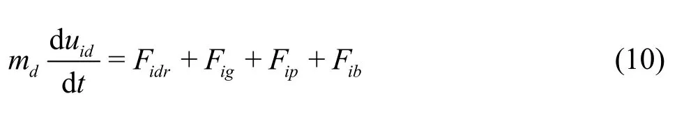
whereFidris the drag force and is defined as follows
Dpis the drag function and is defined by
CDis the drag coefficient, which is a function of the Reynolds number and a closed surface section (Ad).The drag coefficient used in this study is as follows:
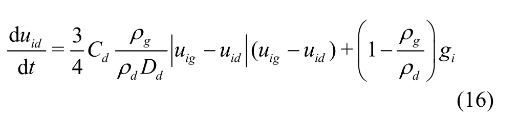
Figincludes the gravity and buoyancy forces and is given as
Fipis the force difference between the inside and outside of the droplet and is expressed as
Fibincludes other interior forces such as magnetic and electric forces.By substituting the above equations in Eq.(10) and dividing bymd, the momentum equation is given as
1.3 The primary breakup modeling
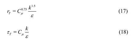
The DIESEL breakup model was used for the modeling of initial jet collapse based on the DDM method.The continuous liquid jet near the outlet of the nozzle consists of a series of big droplets whose sizes are the same as the diameter of the nozzle.The initial atomization is based on initial turbulence effects, cavitation and aerodynamics forces.To determine the effects of turbulence on initial collapse, two scales were considered; the first scale was turbulence lengthwhich was defined in droplet model (m)as the ratio of the droplet volume to its surface, and the other scale was turbulence time
The variation of the droplet size with respect to time for turbulence modeling is given as
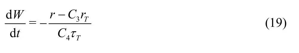
whereC3andC4have constant values, and are selected by the user depending on the problem conditions.The collapse of the cavitation bubbles is considered in the turbulence model with an additional term.So, the turbulence equations are given as:
wherekis turbulence kinematic energy,εis turbulence loss,Cis a constant andSkis the term for cavitation source[26-27].
1.4 Model equations
The RANS method was used to solve the mass and momentum equations of the vapor phase.Conservation of mass is defined as follows
and conservation of momentum is given by
wheretμpresents turbulence viscosity, andsF,are the source terms which accounted for the mass, momentum and exchange of the liquid and vapor phases[28].
2.Modeling cavitating flowe in orifices
The computational simulation of the problem includes two study fields.The first study field is two phase flow of the fuel inside the orifice.A minisac nozzle was chosen as an injector for simulating the flow in the injector.A 300 section of the injector was selected to study the cavitating flow since the injector had a circular cross-section and symmetrical shape.The meshing model and two geometric models of the injector with different orifice angles are shown in Figs.1, 2.
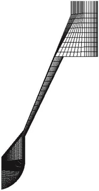
Fig.1 Meshing model of the first study field (injector)
The geometry was meshed at different values of the orifice angles with respect to the injector body,while the modeling was carried out for 6 orifices, and the spray was simulated for one of the orifices because of the symmetric shape of the injector.The diameter of the orifices is 200 μm, and their length is 1 mm[30].The radius of the entrances of the orifices is equal to zero.Therefore, the value of the ratio of the radius of the entrance edge to the diameter of the orifice is zero,and the value of the ratio of the length to the diameter of the orifices is 5 in all cases[26].
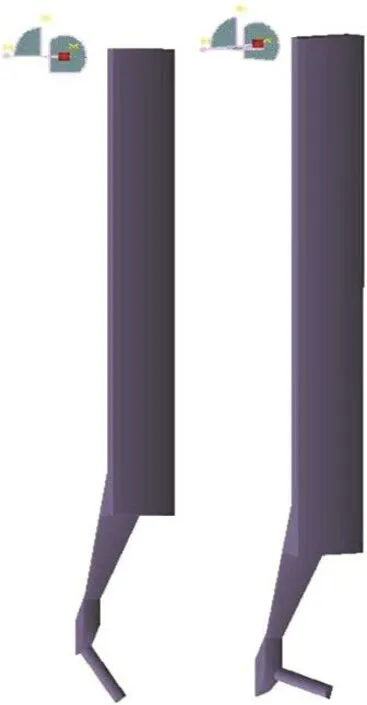
Fig.2 (Color online) Two geometric models of injector with 30° and 90°
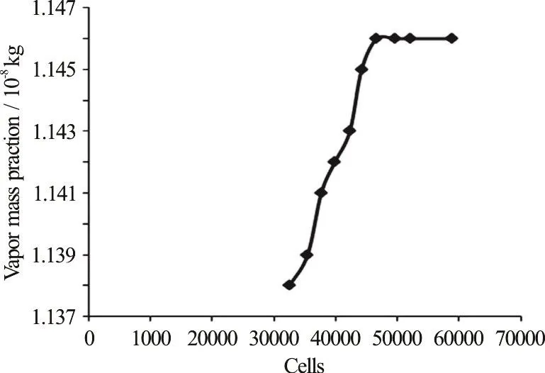
Fig.3 The vapor mass fraction of the orifice with respect to the cell number
The structured mesh was used for meshing the injector body, while the unstructured mesh was used for the injector hole.The hybrid mesh was used for meshing the orifice due to the formation of cavitation in this region.Therefore, the magnitude of the cells was greater than that of the injector body, making it the most important region for the cavitation generation.Many meshing attempts were carried out and finally the results showed an independent behavior from the mesh when the number of cells was 46 673.The meshed injector body and injector hole were connected together with a surface.The results obtained from the outlet of the nozzle were used as initial boundary conditions for the numerical simulation of the spray in the combustion chamber.
It is necessary to study the independence of the results from the meshing.The number of the cells in the first study field was obtained after a great deal of meshing and solving the fluid flow equations.The cell number of the injector body is 22 400, and the cell number of the injector hole is 24 273.Figure 3 illustrates the vapor mass fraction with respect to the cell number for the injection pressure of 100 MPa.The trend of the diagram in Fig.3 is monotonous for the meshes more than 46 673 cells and there is no considerable change after this number of cells.
3.Modeling spray in combustion chamber under the effect of cavitating flow
The second study field was a cylindrical combustion chamber, which was used for simulation of the spray.The diameter of the combustion chamber is 0.05 m, and its length is 0.20 m.The meshed combustion chamber is shown in Fig.4.The structured mesh was chosen for meshing the combustion chamber.The number of cells in the meshed combustion chamber which indicates independence of the results from the number of mesh was 444 444.The wall boundary condition was used for all the combustion chamber surfaces because the inlet and the outlet valves in the cylinder were closed during the fuel injection.The combustion chamber pressure was 2 MPa, and the injection duration was 0.002 s.Air was chosen for the combustion chamber as the gas.
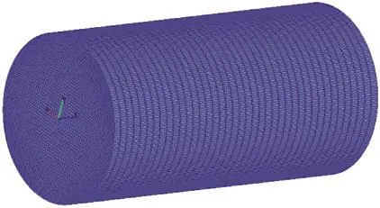
Fig.4 (Color online) Meshing model of the second study field(combustion chamber)
The cell sizes of the different meshes for the combustion chamber are shown in Table1: case 1: 27 777 cells, case 2: 111 111 cells, case 3: 444 444 cells.
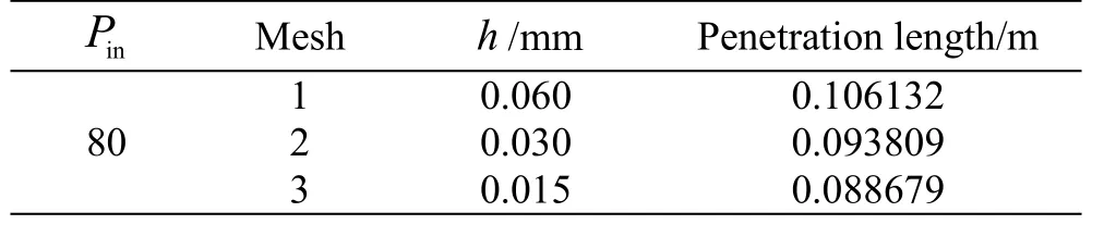
Table1 The cell size of the meshes
The pressure boundary condition was selected for the inlet of the injector hole due to the occurrence of the cavitation phenomenon in the orifice.The symmetric boundary condition was selected for the walls of the orifice, and finally, the pressure boundary condition was chosen for the outlet of the orifice.The inlet pressure of the orifice was 80 MPa, its outlet pressure was 2 MPa, and the temperature of the orifice was 293 K.Meanwhile, the velocity of the engine was 3 000 rpm.The angle of the orifices with respect to the injector body was changed from 30°-90°, and six orifices were used for each injector.The injection system was a common rail, and the needle was in its upper position at 30° and was in a lower position at 150°.The boundary value calculations were performed by using the extrapolation method, and the least square fit was used for the derivation calculations.The turbulence equation was solved with thek-εmodel,and the energy equation was solved with the total enthalpy model.The under relaxation factor for the momentum and pressure were selected at 0.8 and 0.2,respectively.The maximum and minimum iteration values of the convergence factor were 150 and 10,respectively[26-27].
4.Results and discussion
The fluid flow and the injection process are particularly assumed to be unsteady problems.Therefore, they must be considered as an unsteady flow for a certain magnitude of time.The movement of the injector was considered in three time steps.The fuel in the nozzle flowed in the orifice when the needle went up, it entered into the orifice with further going up of the needle, and finally, the fuel flow stopped when the needle went down in the injector.The duration of the injection in this study was 0.002 s.The displacement of the needle was also selected at about 0.25 mm[26-27].
4.1 The effect of the variation of orifice angle on the cavitating flow regime
In this section, the regime of the cavitating flow for different angles of the orifices with respect to the injector body is presented.Figure 5 shows the formation of the cavitation and its extension in the orifices with different angles.As is illustrated in Fig.5(a), the cavitation forms in the beginning of the orifice and it does not extend along the orifice up to the middle of the orifice.The cavitation bubbles approximately extend up to the middle of the orifice, and also they do not separate from the wall of the orifice, as is shown in Fig.5(b).The difference between these two figures will be more obvious in the later figures from the top view.In the last three figures of Fig.5, the bubbly flow passes through the middle of the orifice length,and eventually it reaches the end of the orifice, as shown in Fig.5(e), Meanwhile, the cavitation bubbles separate from the walls of the orifices in the earlier steps, and the bubbles move to the centre of the orifice.Fig.5(e), which is related to 900, shows a complete vapor phase along the orifice, and also, as was predicted, some of the cavitation bubbles leave the orifice and therefore collapse at the outlet of the orifice.
Fig.5 (Color online) The vapor volume fractions in the orifice on the symmetric plane
Figure 6 shows the cavitation formation inside the orifice from the top view and presents the trend of the cavitation along the wall of the orifice for different values of the angle.The difference between cavitating flow at 30° and 70° is more visible from this view.The cavitating flow extends along the orifice wall and does not separate from the wall even at the end of the bubbly flow in Fig.6(a).However, the cavitating flow separates at the end of the vapor flow from the orifice wall.As the angle of the orifice increases, the cavitating flow regime becomes more severe and more bubbles are created at the beginning of the orifice.The cavitation bubbles are not visible from a length of the orifice from the top view in the higher values of the orifice angles, which indicates the movement of the bubbles to the centre of the orifice.The cavitating flow illustrated in Fig.6(e) separates soon after the formation of the bubbles from the wall, and as can be seen extends up to the end of the orifice and leaves the orifice.
Figures 7, 8 show the distribution of the turbulence kinetic energy and the absolute pressure for orifices with 45° and 90°.As is seen, the turbulence kinetic energy at 90° is distributed in a monotone trend, and almost the whole orifice has a high value for this energy.The reason for not exceeding to the higher values for turbulence kinetic energy at this angle is the low value of the injection pressure.However, the turbulence kinetic energy for orifice with 45° shows a lower value along the orifice.The absolute pressure of the 90° orifice is almost same along the orifice, which prepares a suitable condition for the formation of the cavitation bubbles in the orifice.
Fig.6 (Color online) The vapor volume fractions in the orifice from the top view
The relation between cavitation and turbulence is shown in Fig.9.In this figure, the cavitation number, whereandare inlet, outlet and saturation pressures, respectively), which is a key parameter for identification the intensity of the cavitation phenomenon is presented with respect to mean turbulence kinetic energy (TKE).As is shown in Fig.9, the mean turbulence kinetic energy increases with decreasing the cavitation number which indicates that the turbulence intensity increases with increasing the generation of cavitation bubbles.Furthermore, the mean turbulence kinetic energy has lower values for 45° orifice in comparison to the 90° orifice.At lower cavitation numbers which corresponds to higher injection pressures, difference between mean turbulence kinetic energy for the mentioned cases is higher indicating the strong effect of the angle of the orifice on the creation of cavitation bubbles and turbulence.
Fig.7 (Color online) The turbulence kinetic energy distribution in the orifice
Fig.8 (Color online) The absolute pressure distributions in the orifice
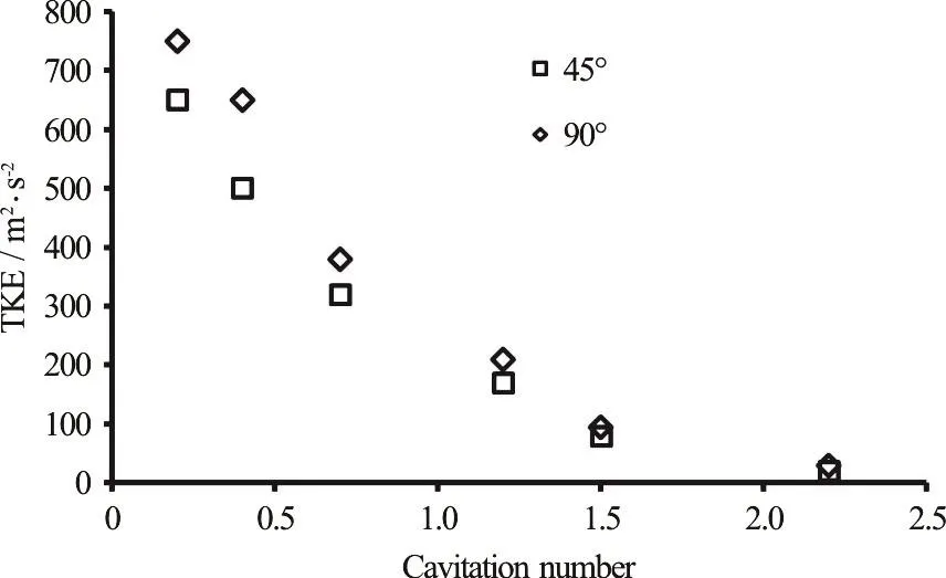
Fig.9 Mean turbulence kinetic energy with respect to the cavitation number
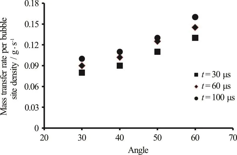
Fig.10 (Color online) Transferred mass per BND for different angles of orifice at different time steps
One of the key parameters which indicates the unsteady nature of the cavitation bubbles is bubble number density (BND).The bubble number density used in this study is selected as 1.0×10¹³.The total transferred mass inside the orifice of the injector is divided by the number of the sites in order to determine the effect of the variation in the angle of the orifice on the amount of the cavitation bubbles.Figure 10 illustrates the mass transfer rate per bubble site densities for different angles of the orifice at three different time steps.The mass transfer rate which is an indication for the generation of cavitation bubbles increases with increasing the angle of the orifice and shows an increasing trend for the higher time steps.In addition, Fig.10 shows that the generation of cavitation bubbles increases with increasing the angle of the orifice.The higher bubble generation is depicted in the vapor volume fraction for the orifices with higher angle.
4.2 The Independence of the results from the meshing
Three meshes with different values of cells were used in this work to investigate the independence of the results.All of the results which were achieved from the three different cases were compared with each other to determine the one that had the best agreement with the experimental results and provided the independence of the results from the number of the meshes.The number of cells is about 130 680 for the combustion chamber.The penetration length and the Sauter main diameter (SMD) are the parameters which were investigated to determine the best mesh.Figure 11 shows the penetration length for the three different meshes.
Figure 11 shows that the selected three different meshes have similar behavior except that the final stages of the injection time, and the mesh with 130 680 cells shows better results in comparison with experimental results, which is illustrated in Fig.12.
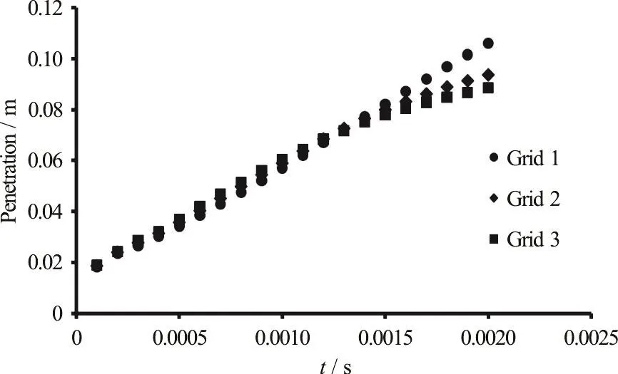
Fig.11 The penetration lengths for different meshes (90°)

Fig.12 The penetration lengths in comparison with other results(90°)
Figure 13 shows SMD for these three meshes,and it shows a good agreement for all of the selected meshes.The penetration length increases with increasing the injection pressure for a certain angle of the orifice.This is due to the severe increase of the pressure difference in the orifice, the creation of more cavitation bubbles, and the changing of the flow regime to super cavitation.The results of these mechanisms lead to the collapse of bubbles in the orifice and sometimes out of the orifice.
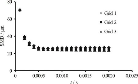
Fig.13 The sauter main diameters for different values of meshes(90°)
4.3 The independence of the results from time step
Due to the unsteady state of the flow in the orifice verifying the results must be sought for different time step values.In this paper, three different time steps were considered to study the independence of the numerical simulation.These different time steps were chosen as 0.00003 s, 0.00006 s and 0.00010 s.The spray parameters are spray penetration and SMD as the previous section.Figures 14, 15 illustrate the variation of the penetration length and SMD against time for different time steps and they each have similar behaviors.The results of this work were compared with other experimental and numerical results[29-30], which are shown in Fig.12.The numerical results of this work in Fig.12 correspond to the time step equal to 0.00010 s.
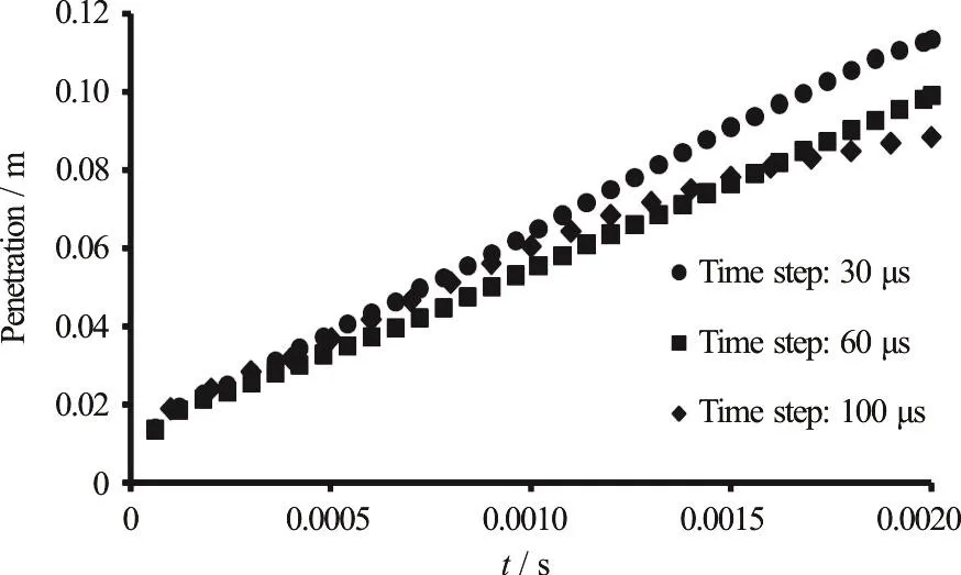
Fig.14 The penetration lengths for different time steps (90°)
4.4 The effect of the variation of orifice angle on SMD
The Sauter mean diameter, which is known as SMD, is one of the most important characteristics of spray.SMD is the ratio of the total volume of droplet fraction to the total surface of the droplet:
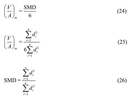
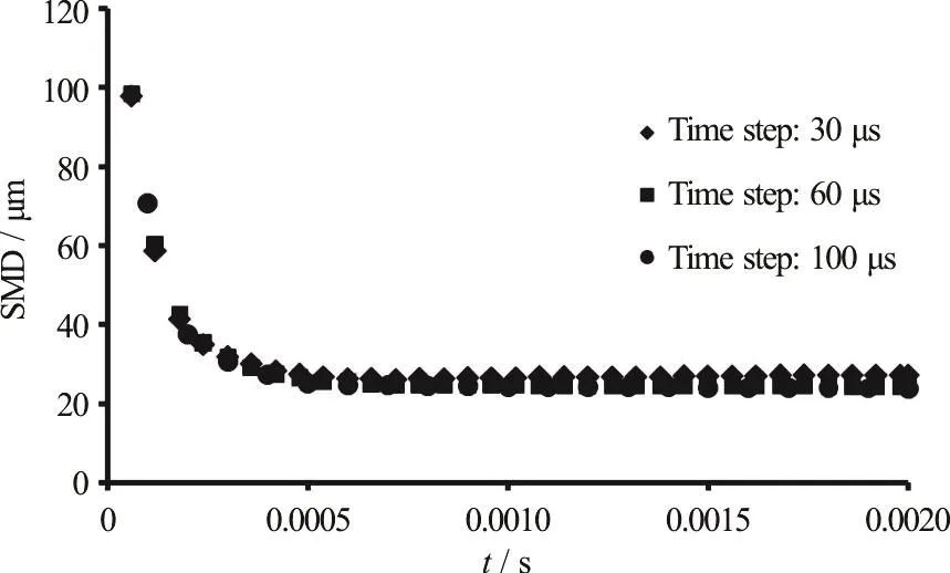
Fig.15 The sauter main diameters for different values of time steps (90°)
If SMD has a low value, the evaporation will increase.SMD does not present any information about the distribution of the droplet size.In other words, two sprays with the same SMD may have different distributions of droplet size.In the experimental work of Aria et al.[31], the following equation was presented for SMD
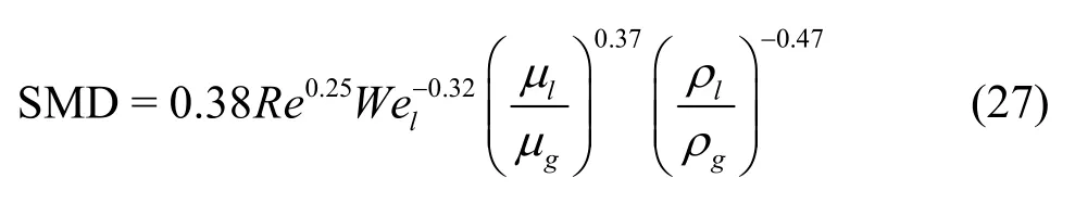
The more the cavitation intensity is increased, the more bubbles are produced.Some of these bubbles collapse in the orifice and cause an increasing in turbulence intensity, which facilitates greater collapse of the bubbles.Therefore, by increasing the intensity of the cavitation in the orifice, the SMD decreases,which causes an improvement of the spray quality[23].To observe the cavitation effect on the SMD, different values of the orifice angle with respect to the injector body were selected (from 30°-90°), and the SMD was calculated during the injection time period (from 0-0.002 s).In Fig.16 different values of the SMD are shown for different values of the orifice angle.SMD decreases when the orifice angle increases, and this leads to a dramatic decrease of the cavitation.
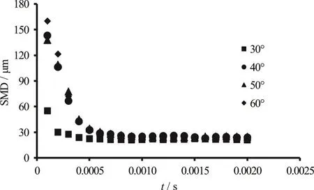
Fig.16 SMD for different values of the orifice angle
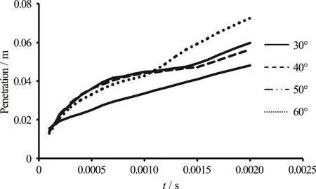
Fig.17 The penetration length variations for different values of angles with respect to time
4.5 The effect of the variation of orifice angle on the penetration length
The penetration length is one of the most important characteristics of the fuel spray.The cavitation phenomenon is also one of the most effective mechanisms on the variation of the penetration length of the fuel spray.In this section, the penetration length is shown for different values of orifice angle.It is known that by increasing the orifice angle with respect to the injector body, the intensity of the cavitation phenomenon in the orifice increases[32].Figure 17 shows the penetration length for different values of the orifice angle with respect to the time.As can be seen, by increasing the orifice angle, the penetration length increases.Since by increasing the intensity of the cavitation phenomenon in the orifice the penetration length increases, it is then deduced that more growth and collapse of the cavitation bubbles occurs for large values of the orifice angle.Furthermore, the validation of numerical modeling of the problem has been shown by comparison of the numerical results of this paper and the experimental results of Walther[30], and numerical results of Berg et al.[29]in Fig.12.
Th e effect of the variation of orifice angle on the spray evaporation
The fuel evaporation strongly affects the fuel-air mixture and consequently the combustion quality.The effect of the cavitation on the evaporation is considerable.
As is shown in the previous sections, increasing the cavitation bubble generation led to SMD decrease,and by increasing the orifice angle with respect to the injector body, SMD decreased.By decreasing SMD,the surface touch of the liquid jet with the air of the combustion chamber increased, and this led to the increasing of the fuel evaporation.Figure 18 shows the spray evaporation with respect to different values of the orifice angle, which shows a considerable raise for evaporation by increasing the orifice angle.
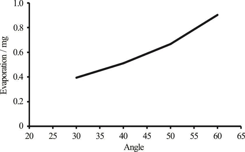
Fig.18 The spray evaporation variations for different values of angles at the end of the injection
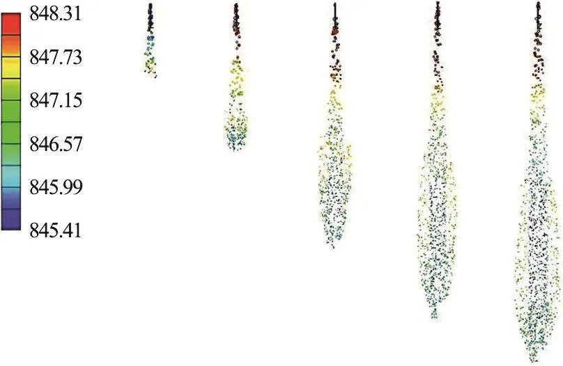
Fig.19 (Color online) The spray densities for angle 90° at injection times: 0.0001 s, 0.0005 s, 0.0010 s, 0.0015 s, 0.0020 s
4.7 Thespray densities for different injection time
The spray densities are shown in Fig.19 for different injection times.This figure shows that the spray does not extend completely at the beginning of the injection and the spray density has a maximum value at the initial stages of the injection.As the injection process proceeds, the spray forms the conical shape, and the fuel density in the combustion chamber becomes higher.This is shown in Fig.19 as the later stages of the injection.At the beginning of the spray,since the liquid jet does not experience the primary breakup, the liquid jet has a very high velocity and density.After primary breakup and the disintegration of the liquid jet into droplets, the spray density along the penetration length decreases.
4.8 The effect of the variation of orifice angle on thespray velocity
At the beginning of the injection, the liquid fuel at the core of the spray has the highest velocity as it enters the combustion chamber.As the penetration length increases, the spray velocity along its axis is higher than that at the other parts of the spray which are far from its axis.
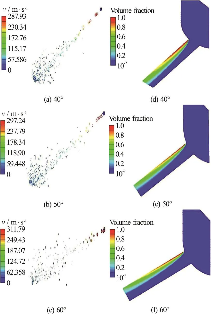
Fig.20 (Color online) The spray droplets velocity distribution and the volume mass fraction of the vapor
By generation of the cavitation bubbles in the orifice, the effective cross section area for the flowing of liquid fuel decreases, and consequently the velocity of the liquid jet of the fuel in the orifice at the instant of entering the combustion chamber increases.Therefore, the generation of the cavitation vapor bubble in the orifice and assumption of the slip boundary condition at the orifice wall leads to the increasing of the liquid jet velocity along its axis.As has been mentioned before, when the cavitation phenomenon occurs in the orifice, some parts of the orifice are occupied by the vapor phase.Thus, the effective area that the liquid fuel passes through decreases.This causes an increase in the liquid velocity and consequently increases the velocity of the spray droplets.As the cavitation phenomenon in the orifice becomes more severe, the generated vapor phase increases, which causes a further increase in the liquid fuel velocity.Figure 20 illustrates the volume mass fraction of the two phase fuel flow in the orifice and the velocity of the droplets of the fuel spray in the combustion chamber for different values of the orifice angle.This figure shows that by increasing the orifice angle, the generated cavitation bubbles become more and the region in the orifice occupied by the cavitation extends up to the outlet of the orifice.Therefore, the velocity of the spray droplets inside the combustion chamber becomes higher.
5.Conclusions
In this paper, th e effect of the cavitation phenomenon in the injector of diesel engines was investigated for different angles of the orifice.The results show that by increasing the angle of the orifice with respect to the injector body, the cavitation phenomenon in the orifice becomes more severe.By increasing the generated vapor bubbles in the orifice,the effective area through which the liquid fuel passes decreases, and consequently the velocity of the liquid fuel in the orifice and the velocity of the spray droplets in the combustion chamber become higher.It should be noted that by increasing the generated cavitation vapor bubbles in the orifice, the turbulence of the liquid fuel flow during its entrance into the combustion chamber increases.
The results show that when the orifice angle with respect to the injector body is 90°, the region which is occupied by the cavitation phenomenon in the orifice extends up to the orifice outlet.By collapsing the cavitation vapor bubbles in the orifice and the possible collapsing of cavitation bubbles in the combustion chamber, the angle of the spray cone increases.
The results show that by increasing the cavitation phenomenon in the orifice, the spray penetration length, as one of the most important characteristics of the spray, increases.The maximum penetration length of the spray occurs when the angle of the orifice with respect to the injector body is 90°.
SMD is another important characteristic of the spray.The results show that by increasing the angle of the orifice with respect to the injector body and consequently increasing the cavitation phenomenon inside the orifice, SMD decreases.This was due to the fact that by increasing the angle of the orifice and increasing the generated vapor cavitation bubbles in the orifice, the primary breakup occurs sooner.
It should be noted that by increasing SMD, i.e.,decreasing the size of the spray vapor droplets, the surface of the liquid fuel droplets which is exposed to the ambient gas increases.Therefore, by increasing the angle of the orifice with respect to the injector body and consequently increasing the generated cavitation vapor bubbles in the orifice, the evaporation of the liquid fuel droplets increases.

- 水动力学研究与进展 B辑的其它文章
- Call For Papers The 3rd International Symposium of Cavitation and Multiphase Flow
- Improving the real-time probabilistic channel flood forecasting by incorporating the uncertainty of inflow using the particle filter *
- A selected review of vortex identification methods with applications *
- Tracer advection in an idealised river bend with groynes *
- Simulation of the overtaking maneuver between two ships using the non-linear maneuvering model *
- The effect of downstream resistance on flow diverter treatment of a cerebral aneurysm at a bifurcation: A joint computational-experimental study *