Ships Bottom Cavities as Shock Absorbers in Waves
Eduard Amromin
Abstract Bottom ventilated cavitation is the successfully proven ship drag reduction technology,but the impact of sea waves on ships with bottom cavities is the substantial concern for a broad technology implementation.The influence of waves on vertical force experienced by such ships is analyzed in this paper using a perturbation technique. The unperturbed cavity shape at given Froude number and cavity length was found from a nonlinear steady ideal fluid problem. The ship response to an impact of a wave of the given length and amplitude is considered as the one-frequency perturbation. This perturbation was found by combined consideration of compressible flow in the cavity and incompressible flow in the surrounding water. Computational examples relate to an earlier tested model with the bottom cavity restricted by skegs. The vertical forces on the model with bottom cavities and in cavitation-free conditions were compared in head and following seas. It was found that within the major part of the consider range of wavelengths the cavity acts as a shock absorber significantly reducing the vertical force pulsation and ship acceleration in waves.
Keywords Ship bottom cavitation .Wavy seas . Mitigation of force pulsation . Vertical acceleration
1 Introduction
Bottom partial ventilated cavitation as a successful ship drag reduction technology has been proven by model tests of Butuzov(1966),Sverchkov(2005),Foeth(2008),Allenstorm and Leer-Andersen(2010),Amromin et al.(2011),Elbing et al.(2013),Zverkovski et al.(2014),Gorbachev et al.(2015),and Matveev et al.(2015)and fullscale experiments of Basin et al.(1969)and Butusov et al.(1990).One may also find the reviews of the technology successes by Sverchkov(2010),Gorbachev and Amromin(2012),and Amromin and Gorbachev(2015).
Nevertheless,the sea wave impact on the pitch and drag of such ships is the substantial concern for the broad technology implementation.So,this study is aimed on an analysis of the cavity effect on vertical force applied to a ship in waves.
2 Numerical Method for Determination of Force Pulsations
Some experimental evidences of the favorable influence of bottom cavities on the wave impact on ships were already obtained.These evidences are shown in Fig.1 plotted with data from Amromin et al.(2011)and Fig.2 copied from Amromin and Gorbachev(2015),but no theoretical/numerical study of the mentioned cavity influence is known and comprehension and extrapolation of the results of model tests remains complex yet.The analysis of ventilated hydrofoils in gust flows by Kopriva et al.(2008)could not be extrapolated for ship bottoms.
As proven by Choi and Chahine(2010),oscillations of ventilated cavities under wave can be satisfactory predicted using ideal fluid theory.Here,the velocity potential is the sum Φ( x;z;t)= Φ0(x;z)+ Φ*(x;z;t)+ φ( SC;h;t).Here Φ0describes the flow around the ship buttock with a steady cavity with the time-average surface SCdetermined by solving nonlinear problems on cavitation at moderate Froude numberswhere L is the ship length,g is gravity acceleration,and Vis the ship speed;Φ*describes unsteady perturbations around the buttock due to the inflow pulsation,but it neglects by oscillation h of the cavity thickness H;φ describes velocity perturbations caused by this oscillation..The flow sketch is shown in Fig.3.Free-surface conditions are considered at z=0 and as a result,sinks are distributed at z>0 symmetrically to the sources distributed along the submerged buttock with the cavity.The dependency of pitch angle on Fr is taken from tests of Amromin et al. (2011) for the model shown in Fig.4,whereas cavitation number σ =2(P∞-Pc)/(ρwV2)for a bottom cavity of the fixed length LCwill be found during solution of the steady problem.Here,Pcis air pressure in the cavity,the inflow pressure is P∞.
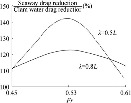
Fig.1 Effect of bottom cavity on drag of a ship model in waves
The model 5694 lengthL=4.55 m and its width B=1.1 m.The towing tank experiments with this model have been carried out in the linear tow tank of David Taylor Model Basin.The tank dimensions are 575 m×15.5 m×6.7 m.The towing speed can be stabilized there with the dispersion of 0.005 m/s.The model was towed free to heave and trim under the carriage.The air supply pipe connecting a fan to the forward part of the niche is seen in Fig.4.The towing tests of the model with air cavity in waves have been carried out at T=L/20.
The numerical technique employed for determination of Φ0and unperturbed(steady)cavity shape was described by Amromin(2007,2012).This iterative technique is based on quasi-linearization of the pressure constancy condition on the cavity surface with the subsequent iterative correction of the surface shape via solving quasi-linearized singular integral equations.For the selected cavity length and Fr,the value of σ will be found from the solution.
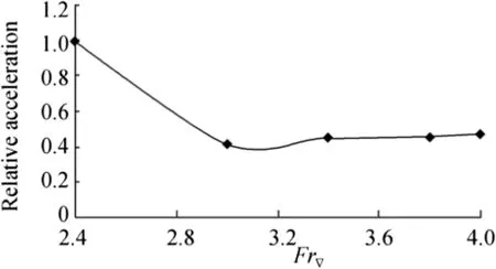
Fig.2 Bottom cavity effect on vertical acceleration of a planing craft in waves of λ ≈ L;Fr▽ is displacement-based Froude number
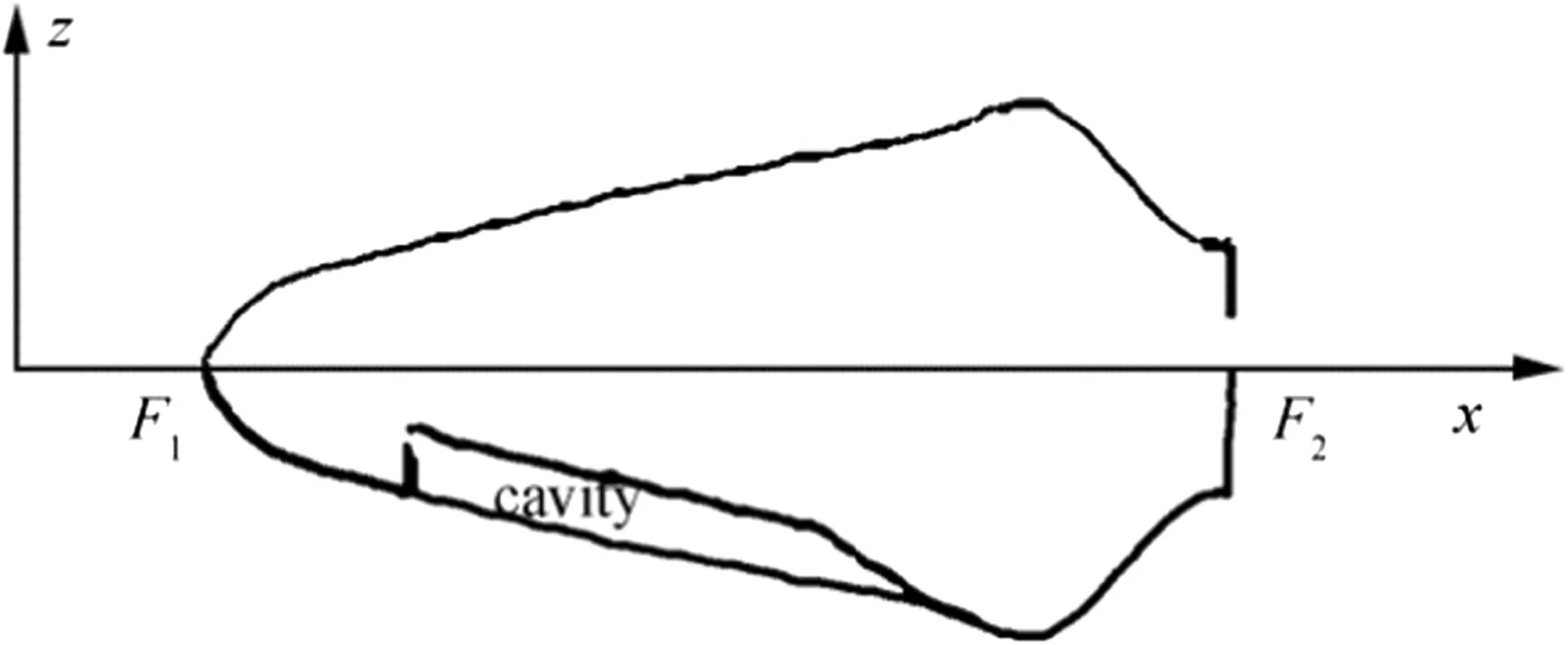
Fig.3 Sketch of flow around a buttock
Indeed,various methods can be used to solve the corresponding ideal fluid problem.However,for a selected cavity length,there is an interval of Froude number without solution,as predicted by Butuzov(1966)and illustrated by Amromin and Gorbachev(2015)in their Fig.4.11,and there is the interval of Fr without stable cavity in experiments,as illustrated by Fig.4.12 of the same review.
As seen in Fig.4,the bottom cavity is restricted by skegs(keels)and the flow in its vicinity is very close to a 2D flow.So,2D problem is analyzed here.
Two ideal fluid flows are considered jointly. The flow within the cavity is compressible and the average density of the cavity content ρ(x)experiences oscillation^ρ( x;t).The water flow out the cavity is incompressible.The water inflow at the buttock points is caused by the ship motion with the constant speed and propagation of a linear surface wave of the given A and λ.One-frequency waves are considered.Thus,all perturbations are proportional to eiωtand following equations describe time-independent perturbation magnitudes only.The velocities associated with Φ∗and φ are assumed to be much smaller than the ship speed and the ratio A/λ of the incoming wave amplitude tow aveleng this also small.For perturbations of inflow velocityquasilinearization of equations is acceptable.
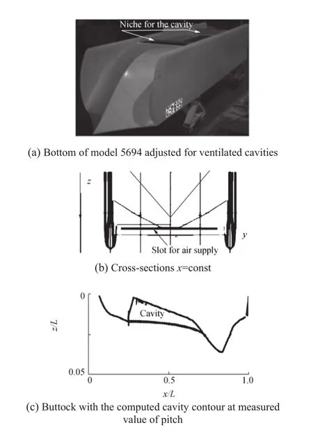
Fig.4 View of the bottom of model 5694 adjusted for ventilated cavities(a),its cross sections x=const(b),and its buttock with the computed cavity contour at measured value of pitch(c)
Response of the contour shown in Fig.3 on the wave impact is similar to the foil response in gust flows.Therefore,it can be described by Birnbaum(1924)equation regularized by Amromin(2017)using an inversion of Cauchy integral(described by Zabreyko et al.(1975)).The employed inversion corresponds to the vortex intensity γ unlimited at the point F1(please return to Fig.3;the segment F1F2is the interval of vortex distribution).Thus,


Here X0and X2are the abscissas of the cavity edges.
On the other hand,h and^ρ are linked by the acoustical equation(the combination of mass and momentum conservation laws for the cavity,derived with exclusion of the velocity,like in Blake(1986)).
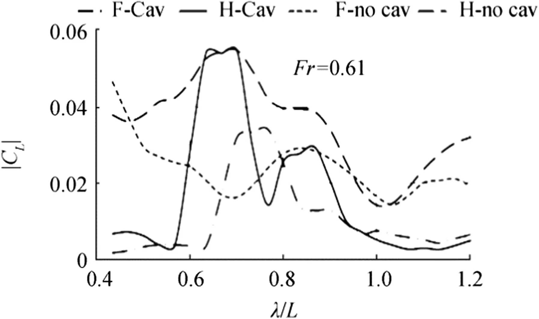
Fig.5 Lift pulsation magnitudes at Fr=0.61(curve F-Cav relates to following seas and H-Cav to head seas with cavity;F-no cav and H-no cav-w/o cavity)
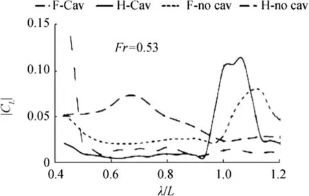
Fig.6 Lift pulsation magnitudes at Fr=0.53(stile of lines is the same as in Fig.5)

Here,c is mixture sound speed(defined by Kieffer(1977),ρwis the water density.The velocity dh/dt coincides with the water velocity component normal to SCand therefore

So,there are four equations for four unknown supposedly small complex variables h,q,^ρ,and γ.There are also boundary conditions dh/dx+iωH^ρ/(Uρw)=0 at x=X2and h=dh/dx=0 at x=X0.
3 Numerical Results and Discussion
The presented computational results relate to A/λ=0.03.Such ratio is very usual for the waves in seas.The considered wavelength range does not include waves much larger than L because,as noted by Amromin(2015),ventilated cavities would be broken apart by such waves,no drag reduction could take place then and bottom cavities should not be maintained in such conditions.
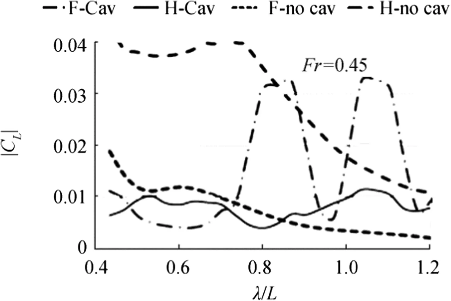
Fig.7 Lift pulsation magnitudes at Fr=0.45(stile of lines is the same as in Fig.5)
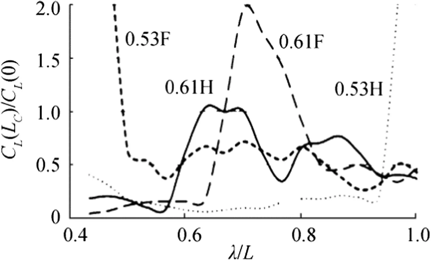
Fig.8 Ratios of lift magnitudes with bottom cavities and w/o them;0.53F means the dependency for Fr=0.53 in following sea,etc.,LC=X2-X0
The contour under consideration is the buttock of the model tested by Amromin et al.(2011)and shown in Fig.4.For 0.45≤Fr≤0.63,cavitation number varies from-0.3to-0.1.So,the air pressure in the bottom cavity is higher than the inflow pressure.
Let us recall that this study is aimed only on variations of the vertical force due to the hull interaction with incoming waves.The forces themselves may be found using more complex numerical methods (like employed by Garo et al.(2012)).
There are no experimental data on the air concentration within the bottom cavity of the tested model 5694.Therefore,for the main computations illustrated by Figs.5,6,7,and 8,it was arbitrary assumed that the cavity volume includes 99%of air and 1%of water.These figures provide comparison of the pulsation magnitude of lift coefficient|CL|(vertical force pulsation normalized by ρwV2L/2)for the contours with bottom cavities and for cavitation-free contours(with the solid contour corresponding to Sc).These comparisons are presented for three values of Fr.
The obtained results allow for certain conclusions on the cavity influence on the interaction of the hull with incoming waves.The ratios of forces presented in Fig.8 are similar to the ratio of accelerations plotted in Fig.2.For λ≈L,these ratios in head seas are close,though the data of Fig.2 was measured for a planning boat running at higher Fr(its bottom is shown in by Sverchkov(2010)in his Fig.1).Also,the smaller ratio of|CL|of the hull with cavity to|CL|of cavitation-free hull in head seas at Fr=0.53 is correlated with the smaller impact of waves on the drag of the model with cavity at that Fr illustrated by Fig.1.
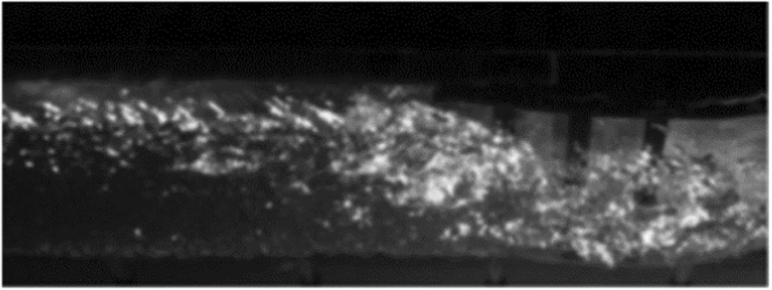
Fig.9 A snapshot of a cavity in the bottom niche
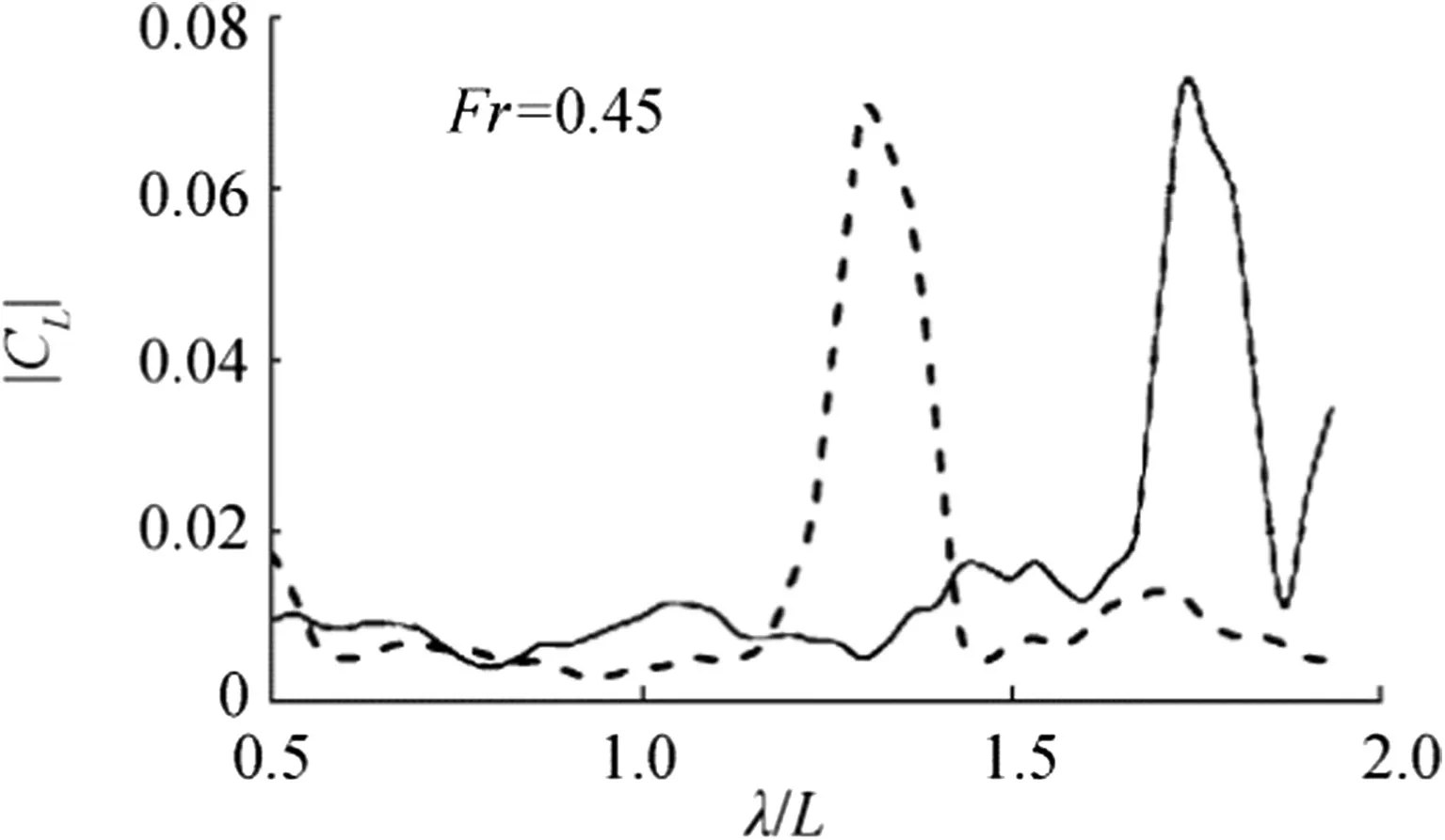
Fig.10 Effect of air distribution in the cavity on|CL|;solid-uniform distribution,dashed-to distribution decreasing at the cavity tail
Though the bottom cavities act as the shock absorbers for the major part of the consider range of wavelength,there are also its unfavorable parts.These parts are more significant in following seas.A qualitative explanation of this unfavorable phenomenon may be provided with the use of some simple scheme(like in Fig.10.3 of Compendium(2015),f.e.).An incoming wave amplifies or reduces pressure along the bottom depending on the wave phase.The ventilated cavity keeps the constant pressure over the significant part of the bottom regardless to the wave phase.For some wavelength,ventilation may not allow for the above-mentioned reduction of pressure and this leads to an increase of vertical loads.
On the other hand,the employed assumption on the constantair concentration along the cavity is not entirely accurate,though just behind a cavitator, it is filed by about a pure gas(as shown by Wu and Chahine(2007)).Indeed,there are water inclusions in ventilated cavities even in specially designed niches.As shown in Fig.9 with a photo from experiments of Arndt et al.(2009),the cavity in the niche is not entirely transparent.So,some inclusions exist even in experiments without waves in inflow.These inclusion fraction increases to the cavity tail.
A comparative computation shows the effect of inclusions(with gradual twofold decrease of the air concentration to the tail)on the lift magnitude.As seen in Fig.10,there is a small effect on magnitude itself,but its peak was switched to the significantly smaller wavelength.Possibly,this concentration could be controlled.
4 Conclusions
The provided numerical analysis shows that for Fr≥0.45 within the major part of the consider range of the normalized wavelength λ/L(comparable with the ship length)the cavity acts as a shock absorber significantly mitigating the force pulsation and ship acceleration in waves.This reduction takes place in both head seas and following seas.The analysis results are in a correlation with the known experimental data.Nevertheless,the cavity may also amplify pulsations(especially,in following seas).The interval of unfavorable λ/L
ratios depends on Fr (the ship speed). The actual limits of such intervals also depend on distribution of the air concentration along the bottom cavity.
 Journal of Marine Science and Application2018年2期
- Journal of Marine Science and Application的其它文章
- Numerical Evaluation of Rudder Performance Behind a Propeller in Bollard Pull Condition
- Comparison of Microbubble and Air Layer Injection with Porous Media for Drag Reduction on a Self-propelled Barge Ship Model
- Dynamic Analysis of High-Speed Boat Motion Simulator by a Novel 3-DoF Parallel Mechanism with Prismatic Actuators Based on Seakeeping Trial
- Effect of Sea Level Rise and Offshore Wave Height Change on Nearshore Waves and Coastal Structures
- Numerical Investigation of Contra Rotating Vertical-Axis Tidal-Current Turbine
- Influence of Short Time-Scale Water-Column Temperature Fluctuations on Broadband Signal Angular Beam Spreading
