Modeling of a Small Scale Wind Turbine for Water Pumping Process:Case Study
Ahmed Boubenia,Ahmed Hafaifa,Mouloud Guemana,Abdellah Kouzou,Mohamed Becherif
1Modelling,Simulation and Optimization of Alternative and Sustainable Systems Team,URMPE,University of Boumerdès 35000,Algeria
2Applied Automation and Industrial Diagnostic Laboratory,University of Djelfa 17000 Algeria
3Faculty of Science and Technology,University of Médéa,26000,Algeria
4FEMTO-ST UMR CNRS 6174,FCLab FR CNRS 3539,UTBM,90010 Belfort(cedex),France
Keywords Modeling system Wind turbine Water pumping Wind power Power output
Abstract This paper deals with the study of a small scale wind turbine implementation for agricultural isolated location.Indeed,the electrification of these locations for industrial and agricultural requirements remains one of the largest current projects,especially when dealing with the use of sustainable sources such as solar,hydro and wind power.The main aim of this work is to validate the feasibility of using wind turbine in this location and to evaluate the performance of the excess energy storage capacity,which in this case is stored as water under the potential energy form.The study represented in this paper has been performed under the case of pumping water station using wind turbine in an isolated location at the north of Algeria,considering that this site fulfills the requirement of a favorable wind potential and a permanent water source.The design of the used wind turbine is based on the constraints of the climate data of the selected location and the lower cost of the implementation means,whereas,the water tank dimensions are is optimized with respect to the daily water consumption data and the available excess of energy to be stored and to be used later for water pumping during the period of wind absence.
1 Introduction
For many centuries,wind and waterfalls have been used to transform wind and water mills to grind maize or transport water,but after discovering fossil sources such as coal and oil,these sources gradually fail until man finds that fossil fuels have caused various dangers,especially the environmental aspect(Zhu et al.,2015).Recently,the mode faced with the reduction of consumption of fossil sources,through the development of sustainable sources as for wind energy technology.Small scales of photovoltaic and wind turbines are usually used in urban areas.
Many researchers have made significant contributions focusing on the ecologic aspect in one side and efficiency improvement of this technology in the other side.Cooney et al.(2017)have characterized the performance of an urban wind turbine based on real data,in the same context Sam Sichilalu et al.(2017)have proposed an optimal control strategy of heat pump water powered by PV and Wind.Wang and Teah(2017)studied the life cycle of horizontal-axis wind turbines at Small scale.De Lellis et al.(2016)have investigated on the economic aspect of the production of electricity by wind turbine and PV with pumping of water,also for the references(Pérez-Díıaz and Jiménez,2016;Zhang et al.,2016)most of their works is focalized on the optimization of wind energy.Certainly these works have con firmed that the use of wind in urban environment is a recent and potential field with such advantages.
Wind resources are used in several sectors,including the agriculture,it is due to the complications of power network connection and the high energy demand associated with these activities.Indeed,wind energy production could be conserved in the form of electrical energy or stored in water energy reservoirs;these two forms of energy can be used for daily life need.In this work,an irrigation system is modeled,in order to determine the optimum factors of the hydraulic efficiency of this system.This system consists of a small scale wind turbine as primary source of electricity,the storage of this electricity is performed by cell battery.The system contains also a water pump to supply the water reservoir.This pumping system gives an advantage of no need of it possible to store electrical energy in the farm(water flows from the reservoir to the farm without electrical power consumption as it falls directly from the reservoir by its own potential gravity).
2 Small scale wind turbine
The principle of wind turbines is to transform the kinetic energy of wind through a set of blades that are directly connected to a generator.There are basically two families of wind turbines,the horizontal axis and the vertical axis wind turbines.They are generally composed of blades,generator,the tower and the mechanical transmission components.Figure 1 shows the performances coefficient of various designs in wind rotors.
Theoretically,when the blades are more numerous,the efficiency improve more.But some cases present contradictive results,which is explained by the correlation of less bales makes the turbine turns quickly and therefore avoid the noise generated and the mechanical wear of rotating parts(Ringwood and Simani,2015).Where the generator component,as shown in Figure 2,is the part that produce electricity,via converting mechanical power of bales there exists two model,synchronous and asynchronous machine It may be a dynamo(product DC)or an alternator(Product AC)(Bouzidi,2011;Mahjoubi et al.,2014).The tower component in small scale wind turbine is one of the most important parts,shown in Figure 3,it is not just a support structure.It raises the wind turbine so that its blades safely clear the ground and so it can reach the cleaner,stronger winds at higher elevations.There are several types of towers such as:
·Tubular Steel Towers:These types are used in all most large wind turbines
·Lattice Towers:they are manufactured using welded steel profiles.The basic advantage of lattice towers is the low cost.
·Guyed Pole Towers:All most the small wind turbines are built with narrow pole towers supported by guy wires
·Hybrid Tower:They are made in different combinations of the aforementioned types.
Matching the small scale wind turbine speed from its low to the required levels is ensured by a mechanical transmission system which includes:
·Contact gears:they are used for transmitting torque and speed at different increasing ratios.they have two main constraints,a complex design is required for the gears system which makes them more expensive to be manufactured and an expensive lubrication is required,
·Transmission belt:is a loop of flexible material used to link two or more rotating shafts mechanically.Belts may be used as a source of motion,to transmit power efficiently,or to track relative movement(Zhu et al.,2015).The efficiency of belts is reduced by 0.5-1%due to belt slip and stretch.Some typical belt types are Veer belts,timing belts,multi-groove belts,
·Chain drives:Power transmission chains are commonly found in bicycles and motorcycles.Noise is usually higher than with belts or gears,but silent chain drives are relatively quiet and Long shelf life because metal chain ordinarily doesn’t deteriorate with age and is unaffected by sun,reasonable ranges of heat,moisture,and oil.
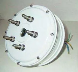
Fig.2 Generator component of small scale wind turbine.
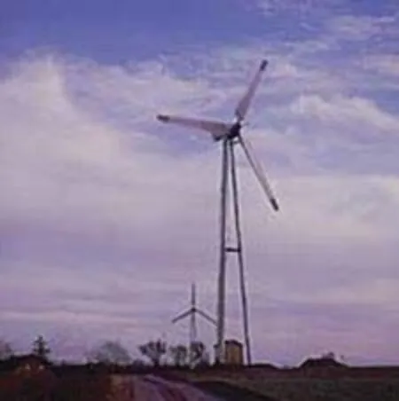
Fig.3 Tower component of small scale wind turbine.
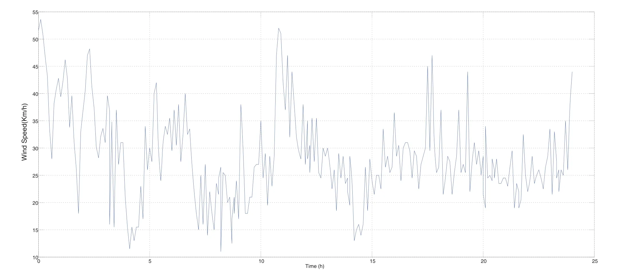
Fig.4 Variation of the wind speed during one day.
3 Design and con figuration of the realized wind turbine
Choosing the right con figuration must first include the database of the study in order to design a compatible shape,feasible and less expensive.In this work the studied location is an Algerian town of Boumerdes called Ammal,located 50 km from Algiers,Tizi Ouzou and Bouira,in the west of Kabylie 36°38’05”North 3°35’26”East.Ammal is a rural location with agricultural vocation and it is a windy area especially in winter and spring period.
The curve below shows the variation of the wind speed during a windy day in the month of February 2016 as shown in Figure 4,due to the reference(Copal et al.,2013).
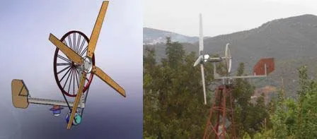
Fig.5 Small scale wind turbine before and after realization.
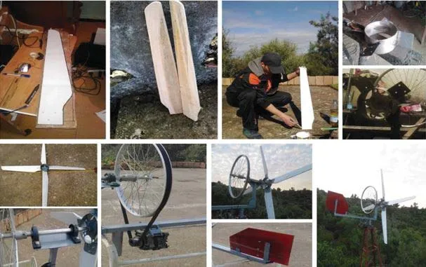
Fig.6 Realization steps of the designed wind turbine.
The designed wind turbine consists of 4 wooden blades made from recovered damaged tables,as shown in Figure 5.Transmission and multiplication of the speed is performed by belt,in a manner so that the large aluminum wheel multiplies the speed of the alternator.The system is equipped with a wind vane which is used to direct the turbine towards the optimal direction of wind,whereas the brake system in this case is performed manually by the isolation of the transmission between the turbine and the generator.The primitive design prototype was made by 3D design software.Simulation software was also explored for performance analysis to introduce the necessary improvements.Figure 6 shows the realization steps of the designed wind turbine.
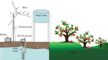
Fig.7 Scheme of the studied system.
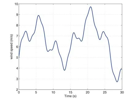
Fig.8 Wind speed profile.
The chosen con figuration is intended for an agricultural need for pumping water from a well to a planted land,it consists of the manufactured wind turbine,the batteries,DC/AC inverter,water pump and the water tank.Nominal velocity of wind turns the wind turbine to produces continuous current via a generator;this voltage will be converted into alternative voltage 220V 50Hz through a DC/AC inverter,the obtained Ac voltage is applied to the water pump which pumps the water from well to the tank placed at a higher level from the ground with an approximate height of 10 m.
The stored water will take a gravity force which facilitates its supply to the land.Part of the energy produced can be stored in batteries once the water level reaches the maximum,this energy can be used when the wind speed is decreasing.In future approaches,this system can be equipped with a hydroelectric turbine which takes advantage of the waterfall to produce electricity that can compensate the lack of wind speed.Figure 7 shows the different components of this chain and its operating principle.
4 Modeling of the chosen con figuration
4.1 Modeling of wind velocity
The opted con figuration of designed wind turbine will be modelled for its principal components,this system includes:the wind velocity,the wind turbine and the mechanical part.For wind velocity modelling,it is clear that the wind resource is dominant in a wind power scheme and so decisive for the estimation of production of electricity and profitability.The dynamic properties of the wind are vital for the study of the entire system of energy conversion as the wind power under optimal conditions is a function of the cube of the wind speed as shown in Figure 8.On the other side the random wind velocity oscillations are based on the sinusoidal functions given by:

4.2 Modelling of wind turbine
In order to estimate the power production by the wind turbine,we established a model that is defined by the wind speed Vw,the calculation of the power production passes by two steps:
4.2.1 Mechanical part model
The mechanical part is formed of the turbine which converts the kinetic energy into mechanical energy and the step-up gear which is the intermediary between the electrical and mechanical part and aerodynamic power here is given by:

Such that the air density isρ=1.3 kg/m3

The coefficient of performance Cpis given by a simplified model as follows:

where C1=0.5716,C2=116,C3=0.4,C4=5,C5=21 and C6=0.0068.
In order to observe the curve of the characteristic(specific speed and power coefficient),shown in Figure 10,the value ofθand the constants C was varied and it is supposed that the average wind speed is Vw=8 m/s and the pitch angle isθ=3°.To estimate the optimal performance coefficient Cpoptand the optimal specific speedλopt.
The wind turbine converts wind velocity to mechanical power attainable from the wind,this conversion is based on the equations given before and the satisfaction of the generator rotation is verified by the equation below:

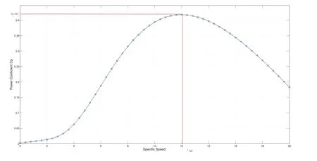
Fig.9 Power coefficient characteristic.
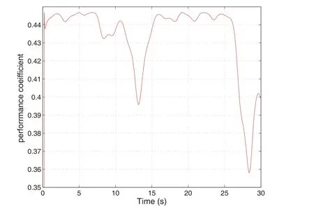
Fig.10 Performance coefficient of the turbine model.
In fact,the drive train in this system converts wind speed to the generator shaft,Figures 10,11,12 and 13 represent simulation results due to the parameters of mechanical part model given in table 1 with wind speed variation,the inertia of the turbine blades is taken from literature results with the same design where its value has some effect on the alternator shaft speed,given as follows:
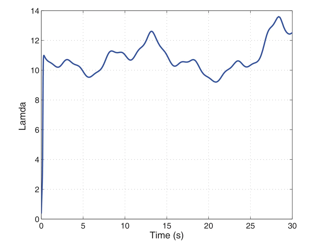
Fig.11 Variation of tip speed ratio.
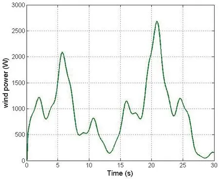
Fig.12 Wind power.

Figure 10 represents the variation of the performance coefficient Cpover time,its value varies between 0.425 and 0.445,it reaches a limit of 0.405 which is justified by a lower wind speed at time between 27s to 29 s.Figure11 represents the variation of the tip speed ratio which is stable compared to the coefficient Pc,tip speed value in this case varies between 10 and 12.

Table 1 Parameters of mechanical part model.
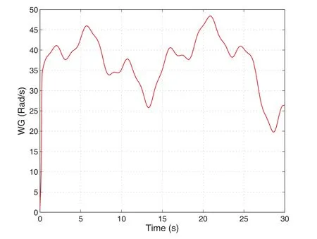
Fig.13 Generator rotor speed.
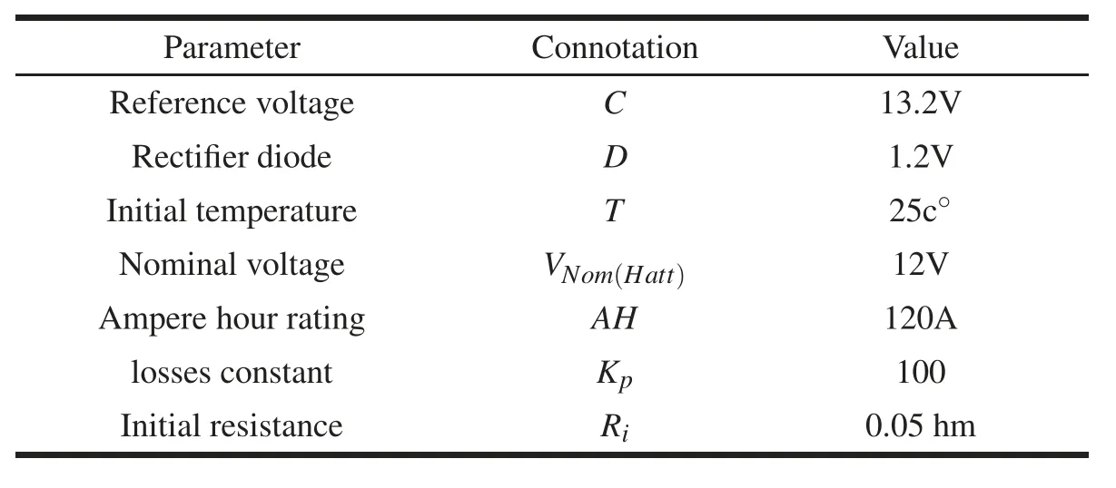
Table 2 Parameters of electrical part.
Figure 12 represents the variation of the wind power obtained,it depends directly on the wind speed and the Cpcoefficient;its value varies between 500 and 3000 W with an average value of 1800 W.Figure 13 represents the generator rotor speed,its value is given between 30 and 50 rad/s with an average value of 45 rad/s.
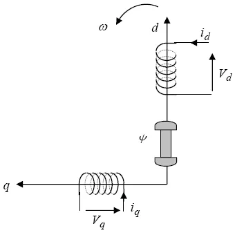
Fig.14 Alternator representation.
4.2.2 Electrical part models
The electrical part consists of the alternator(car alternator is used in this study)which converts mechanical energy into electrical energy,it is equipped with a voltage regulator which controls the voltage at the output of the alternator.Parameters of the electrical part are given in Table 2.
A.Alternator
The analysis of synchronous machine(alternator)model is simplified by Park’s mathematical transformation which was introduced in 1992(Campana et al.,2013;Huang et al.,2015).In the three-phase systems,the phase quantities which include stator voltages,stator currents,and flux linkages,are time varying quantities.By applying Park’s transformation the three phases a,b,c frame can be transformed to two axis frame dq as follows(De Lellis et al.,2016;Tummala et al.,2016):

The inverse Park’s transformation is given by:

Based on the equivalent circuit of the alternator in dq frame as shown in Figure 14,The differential equations modeling the alternator can be expressed as follows:

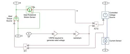
Fig.15 Alternator mode.
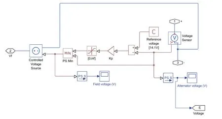
Fig.16 Voltage regulator model.
On the other side,the modeling of the load following the dq frame is expressed as follows:

The alternator circuit representation in Simulink of the present study block is shown in Figure 15,this model represent the mathematical function of rotational speed of the turbine linking with conversion to rad/s2rpm and the regulated voltage Vf.
B.Battery Model
The battery is used in this con figuration to ensure the excitation of the alternator and the energy storage(generic battery)The battery model is represented as follows:

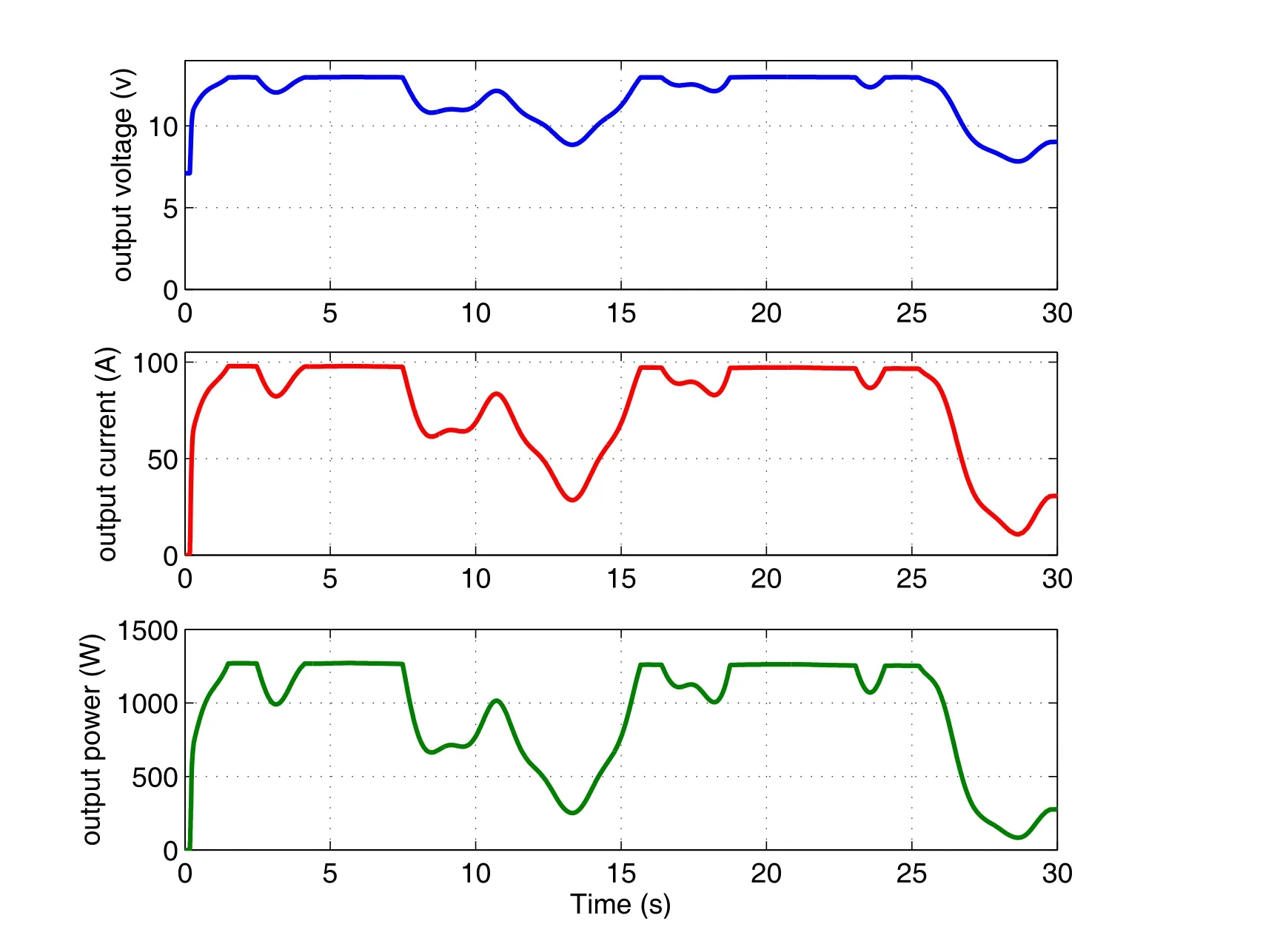
Fig.17 Output data of the generator.
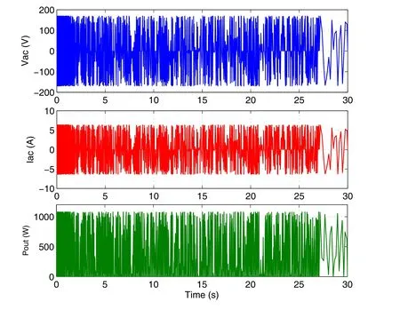
Fig.18 Output data of the DC/AC converter.
where x is the ratio of the ampere-hours left to the number of ampere hours,(AH),for which the battery is rated,V0is the voltage when the battery is fully charged following the nominal voltage.
The established con figuration of the battery model has to satisfy the following conditions:
·The voltage is zero when the charge is zero that is when x=0,
·The battery voltage is V1(the voltage V1≺Vnominalwhen the charge is AH1 parameter value)when the charge is the charge AH1 when no load are V1parameter value,that is when x=AH1/AH.
C.Voltage regulator model
The voltage regulator model is shown in Figure 17,this model is simplified to calculate the output voltage Vfdepending to the battery voltage V and the constant C that represents the reference voltage,this model depend also on the function of the losses constant Kp:

D.DC/AC converter model
Several converter models are existing in the literature(Naci,2003;Ofordile et al.,2014;Belabes et al.,2015;Tummala et al.,2016);in this paper,simplified model was chosen in order to ensure see the output power variation,the following equations were used for in this model:

Figure 17 shows the output data of the wind turbine generator,in the first step the output voltage curve which is given by an average of 12 volts(DC),it can be observed that the voltage dip to 9 volt due to the low speed of wind and this is similar for the electric current that reaches 30A as shown in the second curve,the current here is given by an average of 90 A.the 3rd curve represents the variation of generator output(electrical power);it depends on the voltage and the electric current,it is given by an average of 1000 wats but it dip to 300 watts at the 14thsecond also at 28thsecond due to the current and voltage drop.
Figure 18 represents the variation of alternative current and voltage also power at the output of the DC/AC converter.The first curve represents the voltage variation which is varying between(±200v),the second curve represents the current variation which is varying between(±6 A),the last curve represents the variation of output power which is characterised by an average value of 780 wats.Usually a passive filter with capacitor is used to stabilize the output power.
4.3 Water pump and storage model
There are various mathematical model of water pump such as centrifugal pump and jet pump,where generally their models depend on the primary flow rate,the output flow and the diffuser area.In this study the choice of the water pump depends on the power production,the daily water demand and the level of water tank.A simplified mathematical model was used to model the behavior of the pump during the day following equation(13),its parameters are given in Table 3.

The curve shown in Figure 19 represents the variation of water pump operation over the time.The pump has two malfunction periods at the instant T=12s and T=27s where it can be seen that the flow rate is dropped to 0.2 m3/h,this is due to the shortage of energy production.
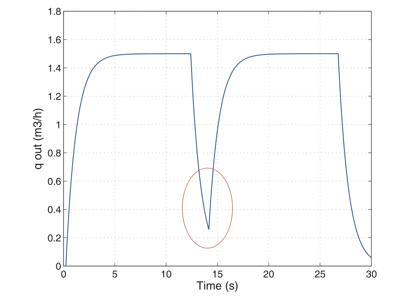
Fig.19 Response of water pump operating.
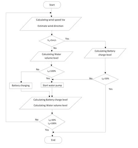
Fig.20 Flowchart of system.

Table 3 Parameters of water pump and storage.
4.4 Controller
The controller is an electronic interface between the pump and source of energy and the tank,it can be ensured via fuzzy logic management,in this paper the system management is not taken in consideration but the flowchart was been designed to eventual work in this topic,shown in Figure 20.
5 Conclusion
This paper gives a new concept of water pumping for agricultural uses,the established system is different from the traditional process,it is a green and economic method as it uses directly a renewable source of energy,this pumping system works for different conditions in the area.Various simulations were made in the aim to choose the optimal con figuration.
The achievement of this installation aims in the medium term to strengthen local capacities of isolated farming areas with rural electrification by the use of new technology away from fossil sources that can influence the environment and the quality of water.This study is motivated by the great achievements of mini wind turbines and hybrid power systems in Europe countries as we hope to get some support in this field regarding the great wind potential of Algeria.
 Journal of Environmental Accounting and Management2018年3期
- Journal of Environmental Accounting and Management的其它文章
- Impact of Climate Change Disclosure on Financial Performance:An Analysis of Indian Firms
- Estimates of the Effectiveness for Urban Energy Conservation and Carbon Abatement Policies:The Case of Beijing City,China
- The Evaluation of Forest Cultural Value Based on WTP:A Case Study in Diebu County of Gansu Province in China
- Audit Judgment Performance:The Effect of Performance Incentives,Obedience Pressures and Ethical Perceptions
- A Simulation Approach to Understanding The Effect of Mimicry on Prey’s Flourishing When Predators Decline Due to Environmental Disturbance
- Optimization of the Gram Staining Method Based on Superparamagnetic Magnetic Nanobeads
