An Explicit-Implicit Mixed Staggered Asynchronous Step Integration Algorithm in Structural Dynamics
Zhiqiang Ma , Lingshuang Kong and Xianlong Jin ,
Abstract: Many engineering applications need to analyse the system dynamics on the macro and micro level, which results in a larger computational effort. An explicit-implicit asynchronous step algorithm is introduced to solve the structural dynamics in multi-scale both the space domain and time domain. The discrete FEA model is partitioned into explicit and implicit parts using the nodal partition method. Multiple boundary node method is adopted to handle the interface coupled problem. In coupled region, the implicit Newmark coupled with an explicit predictor corrector Newmark whose predictive wave propagates into the implicit mesh. During the explicit subcycling process,the variables of boundary nodes are solved directly by dynamics equilibrium equation.The dissipation energy is dynamically determined in accordance with the energy balance checking. A cantilever beam and a building two numerical examples are proposed to verify that the method can greatly reduce the computing time while maintaining a high accuracy.
Keywords: Structural dynamics, node partition, Newmark method, explicit-implicit asynchronous integration, stability condition
1 Introduction
Explicit and implicit time integration algorithms are the two direct integration algorithms in the transient dynamic analysis.
With the improvement of numerical simulation method, there is a growing demand to solve dynamic problems with different temporal and spatial scale. The explicit and implicit algorithms are often combined to solve the problem, in order to take advantage of different algorithms [Hughes (2012)]. There are two kinds of combination approach,one is explicit and implicit algorithms used sequentially to solve the problem in the time domain, the other is to use different family algorithm in different spatial domain.
In the first case, a reasonable approach is to integrate explicit and implicit algorithms into a unified program. The algorithm shift from one family to another according to the appropriate transition condition. It is necessary to deal with the numerical oscillation of explicit and implicit switching [Jung and Yang (1998)]. This kind of method is used to predict springback in sheet metal forming by Narkeeran and Lovell [Narasimhan and Lovell(1999)]. Noels used this explicit-implicit combined method to handle crashworthiness analysis [Noels, Stainier and Ponthot (2004); Noels (2006)]. Bock presented a unified framework for the numerical solution of optimal control problems solved with both implicit and explicit switches [Bock, Kirches and Meyer (2018)].
For another type of combination, the element partition and nodal partition are applied.The structure is divided into a number of subdomains. Each subdomain has its own integration scheme and time step. This kind of research originates from Belytschko and Hughes [Belytschko and Mullen (1978); Hughes and Liu (1978)]. In the later decades,many representative algorithms have emerged. The algorithms can be divided into two categories: with or without overlapping region.
In the context of non-overlapping subdomain coupling method, Schur-type approaches and dual Schur-type approaches are two typical methods. The Schur-type method enforces the displacement or acceleration continuity at the interface [Mahjoubi, Gravouil and Combescure (2009)]. Liu et al. [Liu and Belytschko (1982)] developed a new family of implicit-explicit algorithm which permits different time integration and different time steps to be used simultaneously by element partitioning. Smolinski et al. [Smolinski,Belytschko and Neal (1988); Wu and Smolinski (2000)]. Daniel proposed an implicit subcycling algorithm [Daniel (2003)] developed an explicit subcycling algorithm by nodal partitioning.
For dual Schur-type approsches, Gravouil et al. [Gravouil and Combescure (2002)]proposed a multi-time-step dual Schur approach with a velocity continuity condition on the interface at the fine time step,which referenced as GC method. Prakash et al. [Prakash and Hjelmstad (2004)] developed the PH method which enforced continuity of velocity at the coarse time step but only valid for two subdomains. Karimi et al. [Karimi and Nakshatrala (2014)] compared the GC method and PH method in detail and a new multitime-step monolithic coupling method combining the advantages of both methods is developed.
For overlapping subdomain coupling method, The Arlequin framework is a representative method [Ghanem, Torkhani, Mahjoubi et al. (2013)]. In recent years, explicit-implicit mixed method is gradually combined with adaptive time step or improve the performance and application scope of the algorithm [Soares (2018); Fernandes, Cardoso and Mansur(2017)]. Fekak extended the explicit-implicit method to the field of nonsmooth dynamics[Fekak, Brun, Gravouil et al. (2017)]. Dimarco developed a high order implicit-explicit linear multistep methods for kinetic equations [Dimarco and Pareschi (2017)]. In simulation of three-dimensional grapheme, a hybrid implicit-explicit finite-difference time-domain method is presented [Chen and Wang (2016)].
When mixed with different time steps, the assumption of linear acceleration or linear velocity is applied to tackle the partition boundary conditions. The interpolation process of Lagrange multipliers is used to deal the interface problem .This approach is often regarded as the source of error accumulation and the development of instability, which has led to a bigger error of the calculation result and a harsh condition [Biesiadecki and Skeel (1993)].In this article, we use the dynamic multiple boundary method to handle the explicit and implicit boundary information transmission. The variable of the boundary nodes is solved directly by explicit transfer process. Numerical cases show that our modification results in a higher accuracy than classical interpolation method. The proposed method can increase computational efficiency by using nodal partition and asynchronous time step method.
The rest of this paper is organized as follows: In Section 2, the Newmrak integrator and explicit Newmark based on predictor-corrector formula schemes are introduced to solve the structural dynamic equation. Then, In Section 3 The asynchronous explicit-implicit integration process is proposed to use different time scales and integral methods in different regions. In Section 4, The check of energy balance for the explicit-implicit mixed asynchronous step method is described. In Section 5, two numerical examples are conducted to verify the rationality and feasibility of the explicit-implicit mixed asynchronous method. Finally, conclusions are drawn in Section 6.
2 The Newmark discretized solution procedure
The finite element discretized of a structure which leads to the semi-discretized dynamic equilibrium equation can be written as Cook [Cook (2007)].

Where M is the mass matrix, a is the nodal acceleration vector, C is the damping matrix,fintand fextare the vectors of internal and external force respectively. The given initial displacement and velocity conditions is u(t0)=u0and v(t0)=v0. For linear elasticity, the equilibrium equation is a second-order time differential equation and the internal force vector fintcan be written as

Where K is the symmetric stiffness matrix, v and u are the nodal velocity and displacement vectors. The Eq. (1) can be solved by discretized in time among which the Newmark based time integrator is mostly used.
2.1 The Newmark integrator scheme
The Newmark method has two parameters γand β. Displacement, velocity and acceleration vectors of generalized structural nodes from timetnto timetn+1are based on the equilibrium of the dynamic equation [Cook (2007)]. Subscriptnis used to denote the time step. At the time steptn+1

un+1, vn+1, an+1are the displacement ,velocity and acceleration vectors at time stepn+1 respectively. un, vn, anare the displacement ,velocity and acceleration vectors at time stepn.∆tis the time step. In the Newmark integral method, the displacement un+1in timetn+1is solved from the dynamic equation

The above equation can be rewritten as

The matrix Keffin the above equation is referred as the effective stiffness matrix. The matrixare defined as

In all time steps the effective stiffness matrix Keffremains constant in linear dynamic analysis.
2.2 The explicit newmark based on predictor-corrector scheme
In the predictor-corrector time discretion of explicit Newmark scheme, the predictors of the scheme can be written as Hughes [Hughes (2012)]


If the lumped mass matrix is adopted, the mass matrix M is diagonal and the method is explicit. The nodal acceleration vector an+1can be solved from the dynamic equation

Then, the corrector displacement un+1and velocity vn+1vectors ofn+1 time step can be obtained from the equations

With the provided initial displacement u0and velocity v0conditions, the initial acceleration a0can be solved as follows

3 The explicit-implicit coupling method with overlapping node
3.1 Notation and tag for explicit-implicit coupling
There are two partition methods, namely mesh partition and node partition. The overlapping node partition method is used. The elements fall into three groups: Explicit region, implicit region and interface elements. The schematic of node partition with overlapping node is shown in Fig. 1.
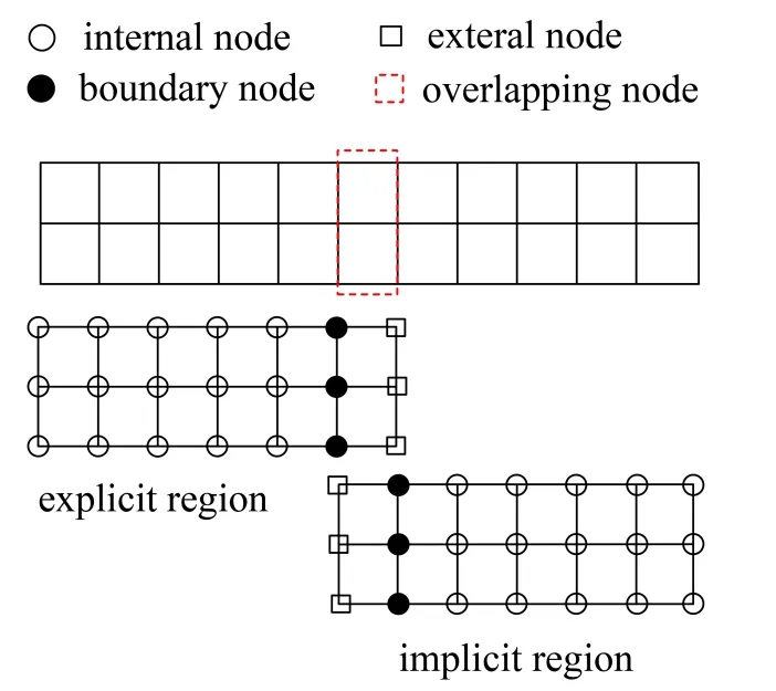
Figure 1: Node partition diagram with overlapping node
For each subdomain, the nodes can be divided into internal node, external node and boundary node. The displacement for explicit subdomain can be described as,and. The superscript letterErepresents the explicit partition and the subscript represents the node type. The displacement for implicit subdomain can be described as,and.The external node in explicit subdomain is the boundary node in implicit subdomain and vice versa.
The time step for the explicit region ∆trcan be defined as


The following notation represents the value of a quantity at subdomain time level. X can indicates displacement, velocity or acceleration

nis the number for system time step andjis for subcycling time step. The asynchronous time step in system time level is shown in Fig. 2
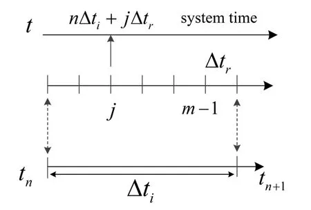
Figure 2: Suddomain and system time step
3.2 The asynchronous step explicit-implicit integration coupling method
The time steps for implicit and explicit region are ∆tand ∆tr. The step ratio satisfies∆t=m∆tr. The multi-layer boundary node method is used to tackle the asynchronous step explicit-implicit coupling algorithm. Multi-layer overlapping node consists boundary node and external node. In order to explain the method clearly, we take the step ratiom=3 for example. Data matching for multi overlapping node is shown in Fig. 3.
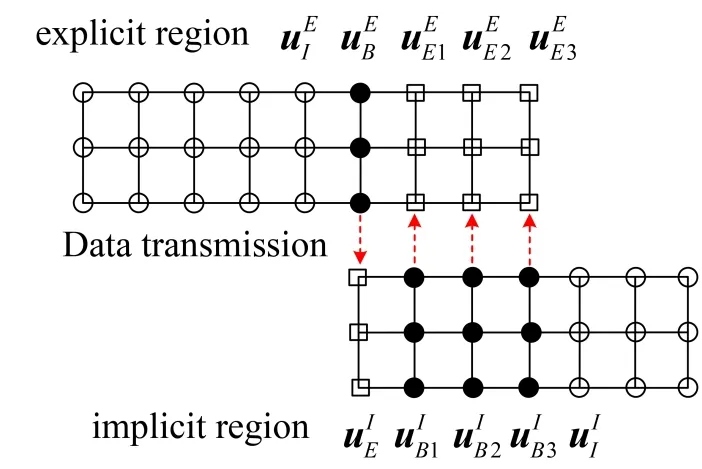
Figure 3: Data matching for multi overlapping node
For explicit region, the nodal displacement is defined asare displacement tags for implicit region.
The equilibrium equation of the linear structural dynamics at time stepncan be partitioned as

The damping matrix C is assumed in the form of Rayleigh damping. While different from the Belytschko method [Belytschko and Mullen (1978)], the predictor corrector form explicit Newmark scheme is used to solve the nodal acceleration of explicit region.During the explicit subcycling process, the explicit region need to be updated all nodes through time stepm-1

The supermarkErepresents all explicit nodes. The nodal acceleration of explicit region can be solved as

Wherej=1, 2, 3…m.
The displacement and velocity of the explicit non-overlapping nodes are corrected by the Eq. (10). The displacement of implicit region is calculated after explicit subdomain. The expression is as follows


The subscriptn+1 means system time (n+1)∆t=. The accelerationand velocityvectors of the implicit region are defined as

With the increase of explicit subcycling time step, the external node which can be solved correctly in explicit region is decrease. The internal and boundary nodes for explicit region can be solved correctly during the subcycling time step. Before the next system step, external nodes need data transmission as
The two-dimensional nodal time-displacement flow of the asynchronous explicit-implicit method is shown in Fig. 4.
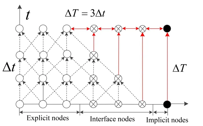
Figure 4: Message passing for asynchronous time step calculation
The proposed method uses the equilibrium equation to solve the acceleration of the boundary node which completely preserves the precision of boundary node.
4 Energy balance check for numerical stability
In the compute process, any unstable result can lead to pseudo energy. By checking the energy balance, the calculation of stability can be checked in real time. For the linear without structural damping case, the system internal energywint, work of the external forcewextand kinetic energywkinare defined as Krenk [Krenk (2006)]

According to the principle of energy conservation, the energy requirements in the processes of solving the dynamic equation have the following equation

e is a very small error tolerance limit whose general order of magnitude is 10-2. The energy balance calculation can be implemented in each sub region if the overall dynamic system is very large.
5 Numerical examples and discussion
In the following two examples, we assume the parameters of implicit scheme γI=0.5and βI=0.25and the parameters of explicit region γE=0.5and βE=0. The explicit-implicit asynchronous algorithm is used to solve the same model under the conditions of different time step ratiosm.
5.1 Case of a cantilever beam in bending
A cantilever beam with rectangle section is presented. A bending load is subjected to the free end point A. The load time curve is shown in Fig. 5. The geometry and finite element mesh are shown in Fig. 6. The maximum force is 10000 N.
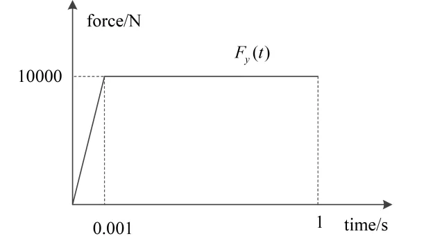
Figure 5: The load time curve for cantilever beam

Figure 6: The geometry and finite element mesh of cantilever beam
The thickness of the rectangular cross-section is 0.03 m. The material is isotropic, linear elastic with Young’s modulusE=210×109Pa, mass density ρ=7800 kgm-3and Poisson ratio ν=0.3. The beam is discretized into isoparametric quadrilateral element. The mesh size of the element in the coarse grid region is about 3 times of the size in the fined area.The whole element number of the region is 1080.
The step of the explicit region is defined by the CFL condition: ∆tcr=5.78×10⁻⁵s. In this case, we use the step ∆tr=5×10⁻⁵s for explicit region. The implicit region adopts a large time step ∆t.
One day the eldest1 brother, who had never done anything but amuse himself from sunrise to sunset, said to the rest, Let us all work hard, and perhaps we shall grow rich, and be able to build ourselves a palace
Under the condition of time step ratio ∆t=6∆tr, vertical displacement of point A is compared with the classical mixed method [Wu and Smolinski (2000)]. The vertical displacements of point A are shown in Fig. 7.
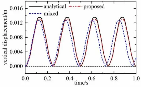
Figure 7: The vertical displacements of point A for different methods
Then we compare the accuracy of the algorithm under three different time step ratiosm=3,m=12 andm=24. Fig. 8 compares the vertical displacement of point A. Fig. 9 is the local enlarged of Fig. 8. It can be find that the displacement curve is basically coincident and the accuracy of the algorithm is not significantly decreased with the step ratio increase.
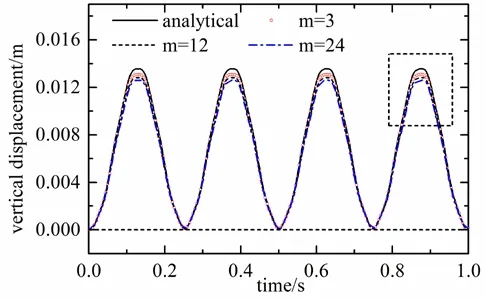
Figure 8: The vertical displacements of point A for different step ratios
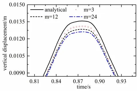
Figure 9: Local enlarged of Fig. 8
In order to analyze quantitatively the computational accuracy, we define sum of displacement errorsuerrand maximum error of displacementumaxtwo indexes as

Where uthemeans the theoretical displacement,upropmeans the displacement calculated by different method andiis time step. The displacement error for different methods are counted as shown in Tab. 1. Although with the increase of the step ratiom, the two precision indexes is increasing for both methods. The interpolation process of boundary data is not involved in the proposed method and it has higher computational accurarcy than traditional mixed explicit implicit method.
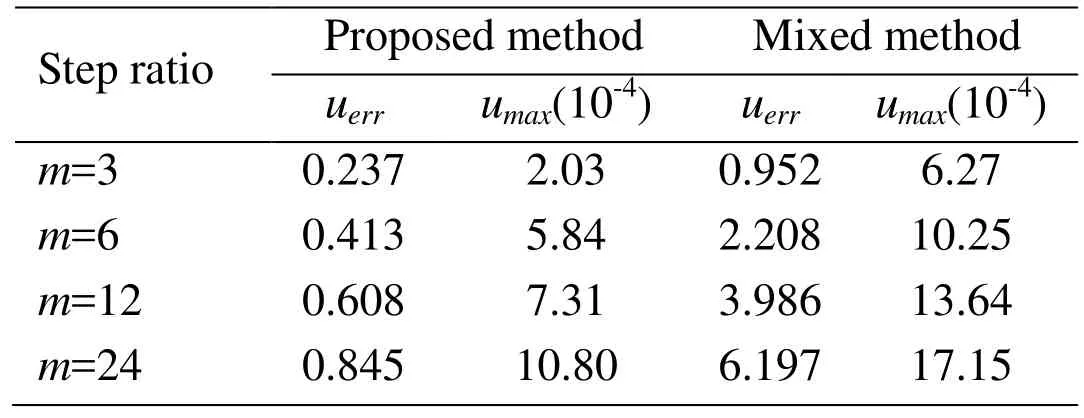
Table 1: Sum of displacement error uerr and maximum error of displacement umax for different methods and step ratios m
The energy curve Fig. 10 shows that the dissipation energy almost zero for step ratiom=12. Namely, the development of pseudo energy does not appear in the computational process. The method is stability for a larger step ratio condition.
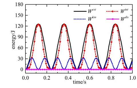
Figure 10: The energy curve of cantilever beam with step ratio m=12
The computation time for different methods is counted as shown in Tab. 2.
The two methods can reduce the calculation time. But the traditional mixed method needs to solve the global stiffness matrix at system time level. This has caused an increase in computing time to a certain extent. The proposed multiple partition boundary method can also reduce the computational time while maintain a higher accuracy.
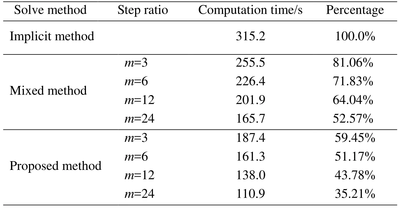
Table 2: Computation time for cantilever beam with different methods and different step ratio m; Step for explicit region and benchmark implicit method are ∆tr=1×10⁻⁵ s
5.2 Case of a building in exploding
This case considers the dynamic response of a building under the explosion shock wave.The shock wave pressure, the overpressure peak value, impulse and duration are used to describe the explosion shock wave. The explosion shock can be simplified as a right triangle pulse load on the front of the structure, retaining its peak and duration characteristics [Ngo, Mendis, Gupta et al. (2007)].

Table 3: Blast load considered in dynamic analysis
Explicit-implicit asynchronous time step algorithm is used to solve the whole finite element simulation model and the explicit-implicit partition is shown in Fig. 11.
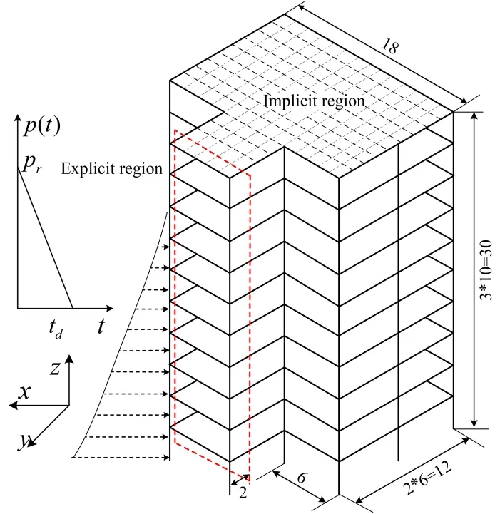
Figure 11: A building model under explosion shock wave
For the response of building structure under earthquake or other impacts, the inter layer displacement angle is an important parameter. Fig. 12 compares the distribution of the maximum inter layer displacement angle of the building structure under five loading conditions [Jayasooriya, Thambiratnam, Perera et al. (2011)]. We choose the step ratiom=3, which means the time step ∆t=3∆tris used in the implicit region.
The results of Fig. 12 show that the response of the building structure is influenced significantly by the mass of the explosive and the distance of the explosion point. When the 2 and 4 of the working conditions, the maximum inter story drifts angle of the structure is close to 4%. And the structural deformation under the load condition 3 is much larger than that of the other working conditions. The maximum lateral drift of the building is more than 10%, which will produce great damage to the building.
Fig. 13 compares the inter layer displacement angle of three different step ratiosmat the same load case 2. With the increase of the step ratiom, the three calculation results have the same change rule.
Fig. 14 is the displacement time curve at the top of the building in the direction of the impact of the shock wave. At the same load case 2, displacement time curve of the explicit method, the proposed method and the classical mixed method (reference method)are compared [Wu and Smolinski (2000)]. The maximum displacement reaches 124 millimeters. It is necessary to further analyze the displacement response of the building under various load conditions.
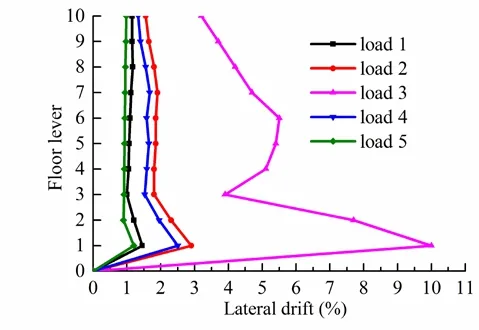
Figure 12: The maximum inter layer displacement angle of the building
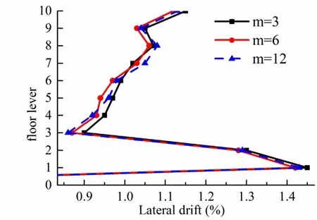
Figure 13: The inter layer displacement angle of different step ratios m under load case 2
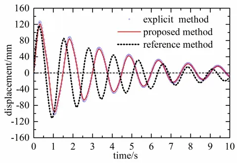
Figure 14: The displacement time curve at the top of the building
The computational efficiency of traditional central difference algorithm and the proposed algorithm are compared in this paper. The CPU time is calculated by the different selected step ratiosm. The computation time consumed for different methods is shown in Tab. 4.
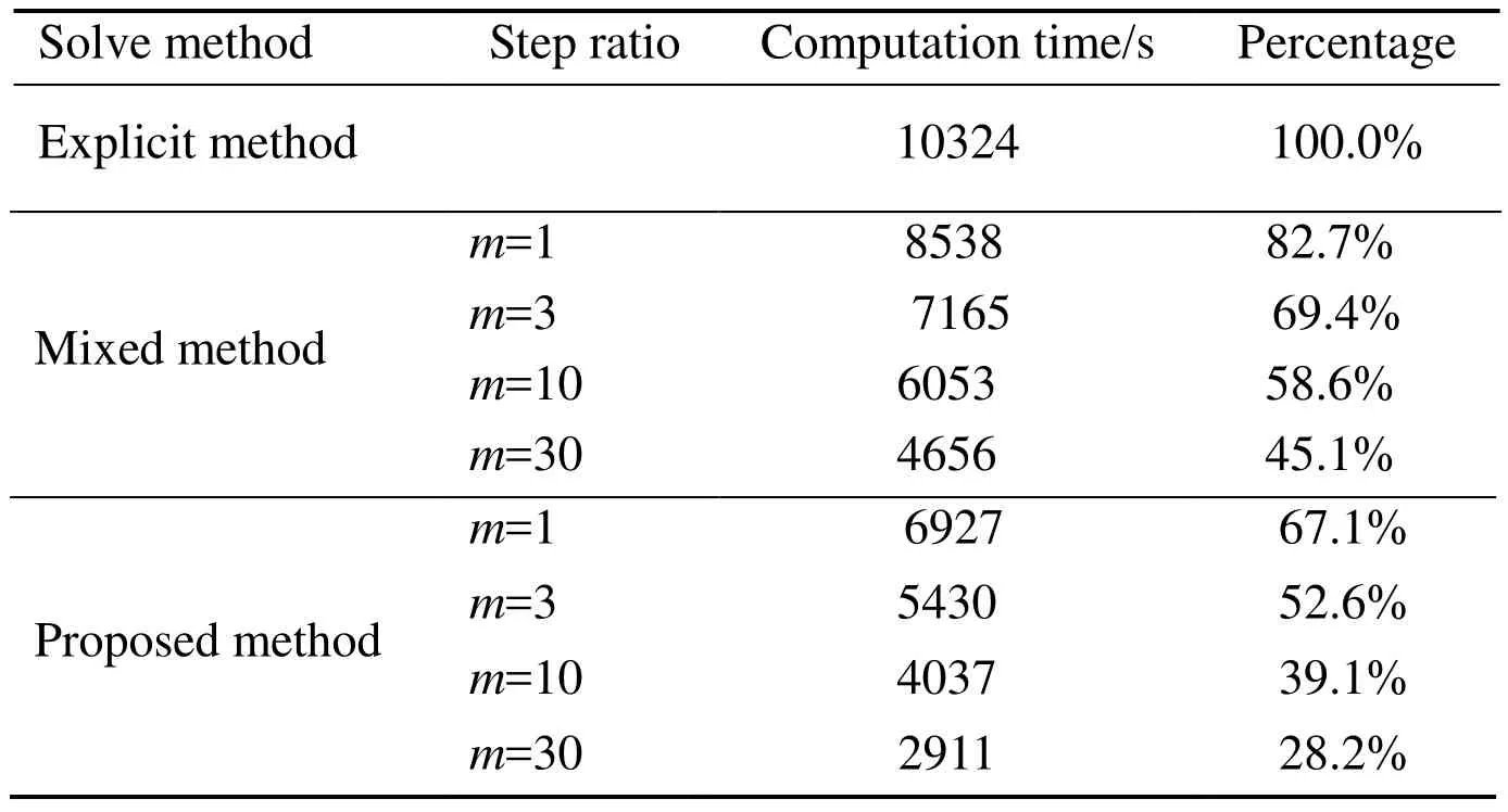
Table 4: Computation time for a building in exploding with different methods and different step ratio m; time step ∆t=1.15×10⁻⁴ s for explicit region and benchmark explicit method
The computation time required for solving the same physical problem is greatly reduced by using the multi-scale discrete grid and the different step size in the time domain. The more nodes are used in large step size, the greater computational efficiency is obtained.The proposed method has the potential for practical application in large scale computation.
6 Conclusions
In many actual dynamic engineering applications, the system has different physical and mechanical properties. The accuracy requirement of the different parts of the system determines the scale of the finite element discrete mesh, which limits the time step.
In this paper, an explicit-implicit multi-time-step method of finite element is proposed to solve this problem. Compared with other time integration analysis methods, this method has several characteristics:
(1) According to the mechanical properties and computational accuracy of a different computing domain, in both space and time domain, the model is simulated with different scales. The more nodes are used in large step size, the greater computational efficiency of the theory can be obtained.
(2) The algorithm uses the changing boundary nodes to deal with the coupling between large and small steps. There is no additional assumption on the boundary node information transfer. The larger time step ratio can be used in theory.
(3) The energy balance method can be used to find the generation of pseudo-energy and unstable development in calculation. It is helpful to get more reasonable calculation results in real time to adjust the calculation step.To a certain extent, the changing boundary nodes method increases the difficulty of preprocessing. If the algorithm can be reasonably parallel and the calculation domain is optimized to achieve load balance, the method must be able to obtain a good performance in solving the super large scale application. It will be the focus of further research.
Acknowledgement:The project is supported by the National Key Research and Development Program of China (2016YFB0201800) and the National Natural Science Foundation of China (No. 51475287 and No. 11772192).
 Computer Modeling In Engineering&Sciences2018年7期
- Computer Modeling In Engineering&Sciences的其它文章
- Investigation on Purine Corrosion Inhibitions via Quantum Chemical Calculation
- Simulation of Solid Particle Interactions Including Segregated Lamination by Using MPS Method
- Mass Transfer of MHD Nanofluid in Presence of Chemical Reaction on A Permeable Rotating Disk with Convective Boundaries, Using Buongiorno’s Model
- Distance Control Algorithm for Automobile Automatic Obstacle Avoidance and Cruise System
- Optimal Model of Continuous Knowledge Transfer in the Big Data Environment
