
Experimental evaluation of a real-time GPU-based pose estimation system for autonomous landingof rotary wings UAVs
2018-06-04 02:48:00AlessandroBENINIMatthewRUTHERFORDKimonVALAVANIS
Control Theory and Technology 2018年2期
Alessandro BENINI,Matthew J.RUTHERFORD,Kimon P.VALAVANIS
DU Unmanned Systems Research Institute(DU2SRI),University of Denver(DU),Denver,CO 80208,U.S.A.
1 Introduction
Fully-autonomous operation of unmanned aerial vehicles(UAVs)requires support for takeoff and landing.Autonomous landing has proven to be one of the most difficult aspects concerning the unmanned navigation of UAVs[1].There are many variables involved in landing an aircraft of any kind,such as wind,weather,dust and obstacles.Furthermore,the limitations on the payload and endurance of small-scale electric UAVs makes longduration and long-distance missions impossible without an automatic refueling/recharging system.Automatic recharging requires the UAV to land on a recharging pad with high accuracy in order to allow the recharg-ing system to work properly.Takeoff and landing autonomously requires a precise estimation of the UAV pose(x,y,z,roll,pitch and yaw)relative to the landing site that can not typically be accomplished with satellite based navigation systems at the precision and framer ate required by flight control systems(typically equal or greater than 50 Hz).
The position accuracy that can be achieved with GPS is around 1 meter in military applications,and around 5 meters in civilian applications.However,using differential corrections,civilian accuracy may be drastically improved.Furthermore,GPS typically provides data with a rate of 5–10 Hz.During unmanned flight,and especially during landing,the aircraft must have the capability to make precise decisions based on the current state of the system.Therefore,providing high-frequency pose estimation becomes mandatory for more precise localization and control performance especially during takeoff and landing.Visual sensors can be successfully used during the landing process since they are able to provide the pose with an accuracy typically greater than GPS,sufficient to complete the autonomous landing task.However,vision systems provide a considerable amount of information that must be processed in order to be effective.
In this paper,we explore the use of GPU-based image processing,in order to perform fast and precise pose estimation of the UAV with respect to the landing pad.The use of the GPU allows fast image analysis even in cluttered environments that otherwise would be difficult to achieve with CPU-based algorithms.There sults show that our system is able to provide pose estimation with a minimum framer ate of 30 fps and an image dimension of 640×480 pixels.Furthermore,the use of a GPU/CPU embedded board allows the UAV to process the video on-board in real time.This avoids the necessity of a powerful ground control station for image processing that would inevitably increase the delay between the acquisition of the image and the use of the data from the image within the control system.Vision-based pose estimation data are further processed using a 12-state extended Kalman filter,in order to remove spikes,noise and to estimate translational and angular velocity on the three axes.The resulting state of the system is provided as input to the autopilot in order to perform smooth control of the quadrotor.
The main advantage of our approach is in the use of a GPU for detecting the marker in order to achieve on board high-frequency pose estimation and marker detection in cluttered environments.The use of the GPU for image filtering and marker detection provides an upper bound on the required computation time regardless of the complexity of the image.The pose estimation algorithm proposed previously has been tested for indoor localization and autonomous landing of a small scale quadrotor.
The paper is organized as follows.After the analysis of the current state of art on autonomous landing using artificial markers(Section 2),in Section 3 we describe the hardware/software architecture of the system.Section 4 describes the pose estimation algorithm in detail,while Section 5 shows the results obtained in on-field experiments.Experimental tests for autonomous hovering and autonomous landing are carried out indoors,where position and velocity estimation rely only on the proposed system.Section 6 describes briefly the on-going and future work,while Section 7 concludes the paper.
2 Related work
Considerable research focuses on vision-based autonomous landing systems,using solutions based on artificial or natural markers[2].In[3],the authors propose a system for autonomous landing based on two cooperating quadrotors operating at different altitudes.The high-altitude quadrotor is responsible to provide an estimation of the low-altitude quadrotor position,which will use its camera for the landing procedure when the marker is detected.The control commands to the lowaltitude quadrotor are sent by a ground control station that is also responsible for analyzing the video stream from both quadrotors.The method proposed in[4]is based on image matching between the current view of the on board camera and a previously known database of geo-referenced images in order to provide position tracking,localization failure recovery and safe landing even when GPS is not available.Keypoints are extracted using SURF.In[5]and[6]the authors propose a visual SLAM algorithm for autonomous navigation in order to search for a predefined landing site based on a known marker.The code runs in real-time using a dual-core CPU,integrating inertial data for reducing geometrical ambiguities.The visual SLAM is based on PTAM[7].The authors of[8]present an autonomous landing system using a predefined marker based on ellipse geometry.The code provides real-time position estimation using an on-board dual-core CPU and high-frequency embedded camera.In[9],the authors propose an algorithm for detecting a marker composed of an H letter(for fardetection of the marker)and concentric ellipses during the last stage of the landing procedure,using a small embedded industrial multi-core platform.
In[10],an algorithm for real time pose estimation using a predefined marker is proposed.The UAV uses GPS for navigation and then switches to vision when the marker is recognized.The code runs on an on-board embedded system.Masselli et al.in[11]describe three different methods using two commercial quadrotors for 6 degrees of freedom(DOF)pose estimation.All of the proposed methods are able to achieve real-time performance without using external aids.In[12],the authors propose a low-cost vision-based localization system using an on-board infrared tracking sensor and infrared markers.They are able to provide 6 DOF pose estimation at high rate.The authors in[13]use a simple marker composed by one circle,to detect the pose of the UAV with respect to a mobile ground platform used for landing.The video stream gathered from the onboard camera is sent to the ground control station to be processed,then,the pose estimation is sent back to the UAV.In[14]the authors describe the design of a landingpad and avision based detection algorithm to estimate the 3D position of the UAV relative to the landing pad.A cascaded controller structure stabilizes velocity and position in the absence of GPS signals by using a dedicated optical flow sensor.The technology described in[15]improves the height estimation provided by the GPS with a stereo camera during the landing procedure.In[16]a vision-based algorithm designed to enable an autonomous helicopter to land on a moving target is proposed.The helicopter is required to identify the target,track it,and land on it while the target is in motion.Authors use Hu’s moments of inertia for precise target recognition and a Kalman filter for target tracking.
The authors in[17]propose an algorithm for providing visually-guided unmanned aerial vehicle(UAV)control using visual information that is processed on a mobile graphic processing unit(Tegra TK1 Processor+GPU).In[18]the authors propose a pose estimation algorithm based on Particle Filter,ableto estimate the6 DOF of the camera with a computation-time of 39 ms per frame and image resolution of 320×240pixels.Table 1 provides a comparison of the analyzed papers.
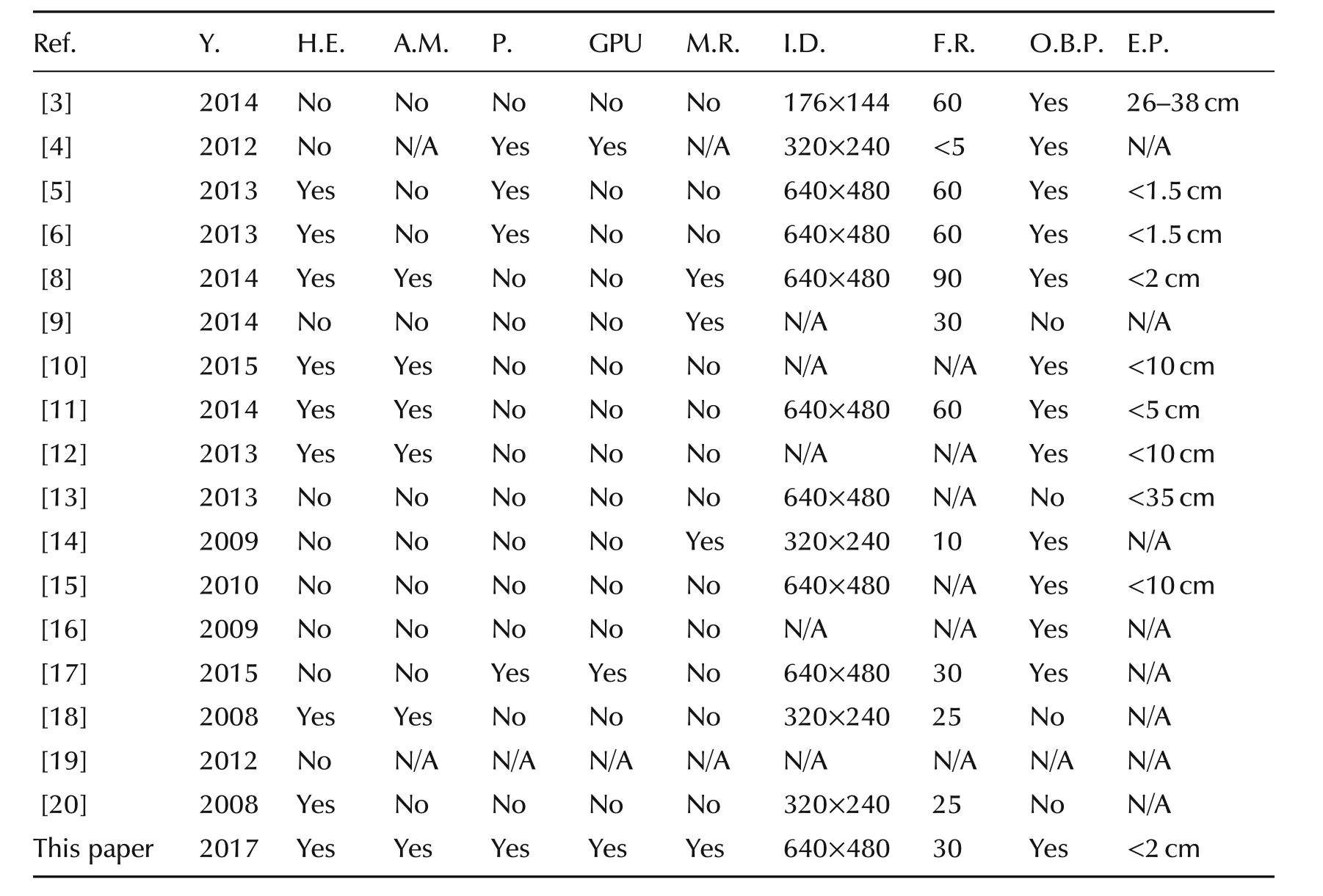
Table 1 State of the art on autonomous landing using artificial markers.
Table 1 shows a comparison of the recent paper on autonomous landing:Y.is year of publication,H.E.describes if the proposed approach is able to estimate the heading,A.M.means asymmetry of the marker and describes if the eventual asymmetry of the marker can be used to estimate the yaw,P.means parallelism on code and describes if the proposed algorithm exploits multi threading for speed-up the image elaboration,GPU describesif parallel computing on GPU is used,M.R.stands for marker replication and describes if the marker is replicated to allow the UAV to estimate is pose on the final stage of the autonomous landing,I.D.reports the image dimension of the frame,F.R.describes the frame rate,O.B.P.reports if the proposed approach uses on board processing for image processing,and E.P.describes the error position of the corresponding proposed algorithm.
The use of GPU for real-timeon-board image processing is still limited.Most applications rely on CPU-based systems,some others leverage a more powerful ground control station to process the stream video.The proposed approach,compared to the state of art,aims to evaluate and exploit the use of an on-board GPU-based embedded system for precise pose estimation with realtime performance,using a pre-defined marker.Our approach exploits the GPU not only for image processing but also for parallel computation in order to discriminate the marker even in cluttered environments.The marker used for pose estimation is based on a series of circles organized such that is possible to estimate the 6 DOF of the camera.The pose estimation is carried out using the pin-hole model and the intrinsic parameters of the camera,obtained through a calibration procedure.Furthermore,the center of the marker contains areplication of the marker itself,which is used to estimate the pose when the camera is close to the landing pad.This paper is an extension of our previous work[21].The algorithm described in[21]has been implemented on the nVidia Jetson TK1 mounted on a custom quadrotor,in order to perform the actual autonomous landing task.The algorithm has been tested extensively in laboratory before implementing it on the embedded system.More details about the laboratory evaluation can be found in our previous paper.Furthermore the whole system has been re-designed in order to be adapted to different VTOL UAVs.
3 Hardware system description
The system for autonomous landing is based on the detection of a fiducial marker the dimensions of which are known a priori.From an hardware point of view,the sensor is composed by the following items(see Fig.1):
·USB 3.0 camera with a resolution of 640×480 and a maximum framerate of 60 fps.
·Camera mount with antivibration support.
·GPU-based pose estimation algorithm implemented on Jetson TK1.
·Landing surface with fiducial marker.The marker is composed of a series of circles that allows the pose estimation of the helicopter w.r.t.to the center of the marker(see Section 3.4).The pose estimation is provided as input to the control system in order to let the UAV land at the center of the marker.The landing platform is mounted on the top of a self-leveling mobile ground robot like the one described in[22].
For our experiments,the vision-system is mounted on a customized quadrotor equipped with the Pix Hawk autopilot.Adetailed representation of the hard ware configuration is shown in Section 3.3.The following paragraphs describe all the hardware and software components;the pose estimation algorithm is described in detail in Section 4.
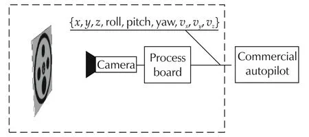
Fig.1 Block diagram of the pose estimation system.The module responsible for image processing and pose estimation is included in the dashed rectangle.The interface with the autopilot is based on serial communication.The data provided by the pose estimation module are:3D position,3D attitude,3D velocity.Other information(such as a flag describing the detection of the marker)is also included in the packet of data.
3.1 USB 3 camera
The camera used in these experiments is a commercial camera,produced by IDS®,equipped with a wide angle lens.The camera model is UI-3241LECand is char-a cterized by a maximum resolution of 1280×1024 pixels(1.31 MP),an image sensor of 1/1.8",global shutter and a pixel size of 5.3μm1More information about the camera used can be found at https://en.ids-imaging.com/store/ui-3241le.html.The UI-3241LEC has been selected among many other cameras since:
·Use of global shutter:As explained in Section 3.2,the acquisition of frames from cameras using rolling shutter creates distortions on the acquired frame,especially when the cameras is subject to vibrations.Our algorithm for the detection of the marker is based on geometrical considerations of the marker:distortions of the frames could make the marker more difficult or impossible to detect.The use of global shutter along with anti-vibration systems improves the detection of the marker.
·High frame rate:The selected camera allows to acquire videos with a frame rate of 60fps and image quality up to 1280×1024.Transfer is done using USB 3.0 protocol.
·Very high sensitivity to light in CCD quality.
·Compatibility with the Jetson TK1 board.
·The provided SDK allows to modify all the camera parameters from code.
The camera sensor is calibrated using the chess-board pattern.The set of intrinsic coefficients and distortion coefficients are used for the frame undistortion(performed in the GPU as part of the frame pre-processing(see Section 4).
3.2 Anti-vibration camera mount
Preliminary tests were conducted using a USB camera with rolling shutter.Because of the high frequency vibrations that affect the quadrotor during flight,the images acquired using such mechanism were difficult to process.In particular,the rolling shutter caused skew effect and wobble effect on most of the frames,as visible in Fig.2.
In order to reduce the vibrations caused by the spinning motors while in flight,in addition to global shutter,a camera mount with anti-vibration system has been designed.The components have been constructed using 3D printing technology.Several tests have been carried out while choosing the correct dampeners.Based on experimental tests,the stiffness of the damping ball plays an important role.Considering the weight of the camera and the distance of the camera center of mass from the based of the anti-vibration system,a too soft set of damping balls would not be able to reduce effectively the vibrations caused by the motors.In Fig.3,the actual realization of the anti-vibration system mounted on the bottom side of the quadrotor is shown.The camera is aligned with the center of mass of the quadrotor,in order to avoid lever-arm effect on x and y axes.We did not consider the lever-arm on the z axis since the distance between the camera and the IMU is around 5 cm and the effect during the landing phase(when the quadrotor is mainly in hovering position with roll and pitch close to 0 degrees)can be neglected.
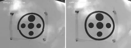
Fig.2 Effects caused by the rolling shutter mechanism.On the left,it is possible to notice a discrepancy in the image.The lower part of the image has been acquired at a different time with respect to the upper part.On the right the“wobble effect”(or jello effect)is visible.
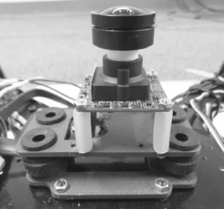
Fig.3 Antivibration camera system mounted on the bottom of the quadrotors.The camera is mounted using 4 standoffs to ensure that the rigidity of the cable doesn not reduce the benefit of the anti-vibration system.
3.3 Quadrotor and autopilot
The quadrotor is based on the Arducopter frame and is equipped with four motors 980kV,four 10×4.5 propellers and two 3S Lipo batteries connected in parallel.The autopilot used for controlling the quadrotor is the well known PixHawk2More information about the PixHawk can be found at the following link:https://pixhawk.org/.The autopilot is connected with the Jetson TK1 using a serial connection(Fig.4).A logic level adapter has been used in order to allow the communication between the 1V8 Jetson UART and the 3V3 Pixhawk UART.
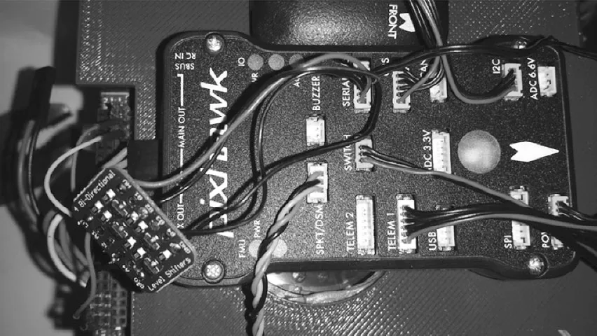
Fig.4 Serial connection between the PixHawk autopilot and the Jetson TK1.On the left the logic level converter is visible.The ground pins are shorted.The 3V3 power is provided by the Serial 4/5 connector on the PixHawk.The 1V8 reference voltage is provided on Pin n.3 on the Jetson TK1.
A software interface for the communication between the autopilot and the Jets on board has been implemented and tested.The soft ware interface,implemented as a library,called AP_Vision Pose,can be found on GitHub3https://github.com/alessandro-benini/ardupilot/tree/master/libraries.A detailed representation of the hard ware configuration is shown in Figs.5 and 6.
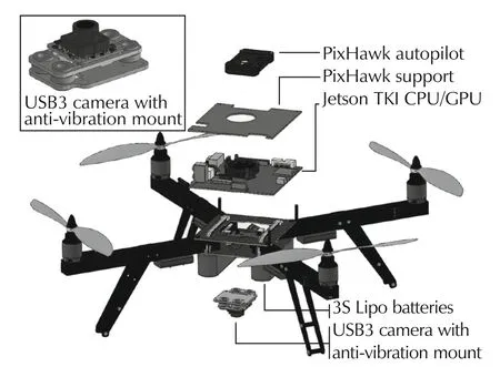
Fig.5 3D model of the quadrotor.
The system is composed by 4 layers:the PixHawk Autopilot connected with the Jets on TK1 through serial port,the Jetson TK1 for image processing,the frame with power distribution modules and lipo batteries,and the USB3 camera with plastic support and 4 dampeners.The4 damping ball sallow there duction of the vibrations that would affect the quality of the image.
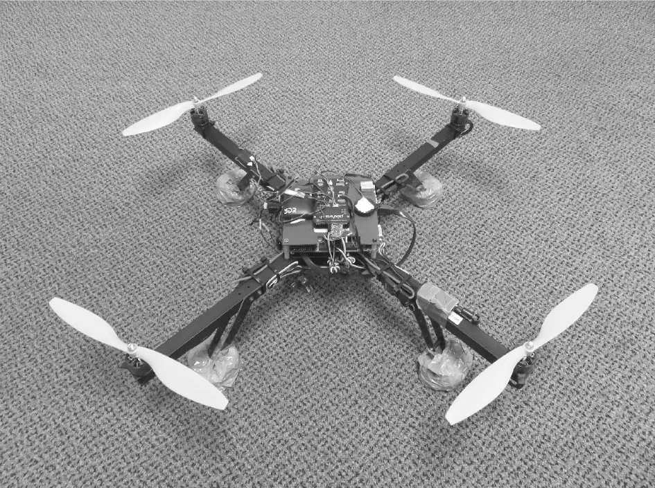
Fig.6 The quadrotor configured to test the pose estimation algorithm.
3.4 Structure of the marker
Fig.7 shows the marker used for pose estimation.The main structure of the marker is composed of two concentric circles.The inner area contains four circles arranged in such a way that their centers corresponds to the vertices of a square.The center of the square coincides with the center of the two concentric circles.The two concentric circles,named main structure of the marker are used to detect the marker on the video stream while the four circles,named inner ellipses are used for estimating the pose of the UAV.The central circle contains a replication of the marker with opposite colors in order to estimate the pose of the helicopter even during the last stage of the landing phase,when the camera is close to the landing surface and the field of view of the camera does not allow to capture the outer marker.We will refer to the replication of the marker as inner marker.
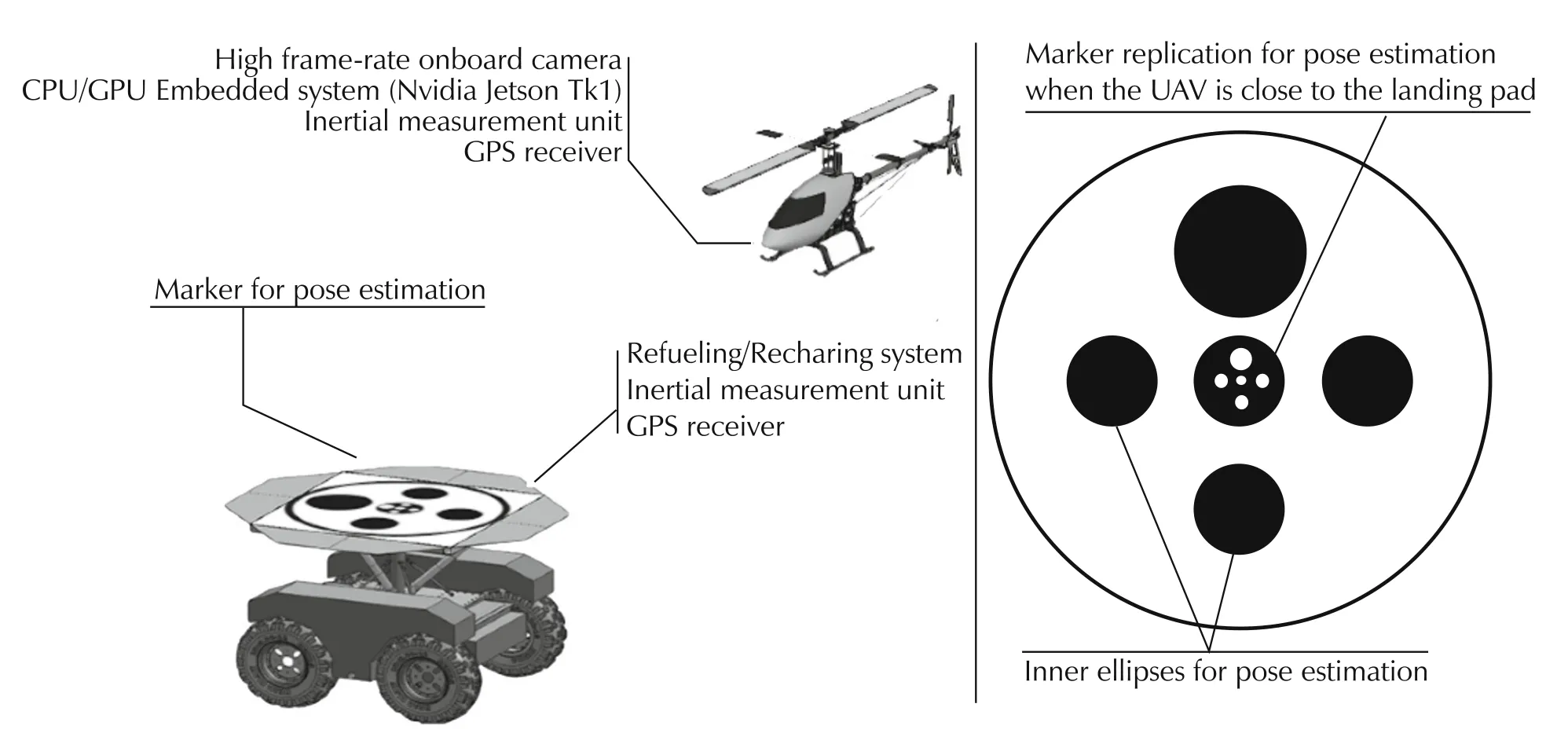
Fig.7 Overview of the system.On the left,the landing system with the description of the main components of the helicopter and the ground robot.On the right,the actual shape of the fiducial marker.
4 Pose estimation algorithm
The proposed algorithm for pose estimation is part of a system that will allow the UAV to achieve full autonomy,from take-off to landing.The proposed algorithm improves the position estimation of the UAV during the approach of the landing area,where the marker is in the field of view of the camera.Until the UAV does not reach the landing area,the algorithm does not produce any information and the navigation of the UAV is based on other sensors such as GPS and IMU.In this section,we will focus on the design and implementation of the poseestimation system,providing a detailed description of the algorithm implemented.
Fig.8 shows the high-level flow chart of the proposed algorithm.The main steps that compose the algorithm can be summarized as follows:
·Frame pre-processing:the first phase consists of applying filtering algorithms in order to enhance the frame quality before the detection phase.After the raw frame is acquired from the camera,it is sent to the GPU memory,where the image is first converted to gray and then blurred in order to reduce the noise.The filtered frame is then used as input for the Canny edge detection routine.The threshold used on the Canny edge function has been chosen through experiments with different light conditions.All the above operations,conversion to gray,blurring and Canny edge detection are carried out using gpu-based OpenCV functions.The resulting pre-processed frame is sent back to the CPU memory for contour searching,since the OpenCV library currently does not provide a GPU version for this function.The transfer of data between the host memory and the device memory represents the typical bottleneck in using the GPU for parallel computing:the time required for uploading and downloading data between the host and the device memory could make the use of GPU not effective.Our algorithm has been optimized in order to minimize the transfer of data between CPU and GPU:the pre-processing of the frame is carried out on the GPU with just one transfer of data.After uploading the raw frame,the results of the subsequent operations(conversion to gray,noise filtering,edge detection)are stored directly in GPU memory,using pre-defined variables.Only the final processed frame is sent back to the CPU memory for the second phase of the algorithm.
·Contour detection:the contour detection is carried out on CPU using the findContour function provided by the OpenCV4http://opencv.org/library with the flag RETR_CCOMP.This flag retrieves all the contours and arranges them on a 2-level hierarchy:external contours of the object(i.e.,its boundary)are placed in hierarchy-1,while inner contours are placed on hierarchy-0.All the contours belonging to the hierarchy-1 and with at least 6 vertices are placed to the list found Ellipses.This list contains,for each ellipse,the following information:index,center coordinates,area of the ellipse,height and width of the bounding box.The index is a progressive number assigned to each ellipse during the detection phase.The ellipses that does not satisfy the above constraint or are too small,are discarded.The area of each ellipse is evaluated considering the moment of each contour(m00).(see Fig.9).
·Find Marker Routine:the list found Ellipses is uploaded to the GPU in order to detect the marker,following the schema described in Fig.10.This phase will be described in detail,in Section4.1.
·Detection of coordinates of inner ellipses:after the detection of the main structure of the marker,the algorithm starts looking for the four inner ellipses in the area delimited by the two concentric circles.The coordinates of each inner ellipse,expressed considering the center of the marker as origin of the reference system,will be used for the pose estimation function.
·Pose estimation:the coordinates of the four inner ellipses,along with the information about the structure of the marker,are passed as input to the pose estimation function.This function is based on the GPU version of the solve PnPRanscac,provided by the OpenCV library.Since the image is undirstorted before the initial frame pre-processing,the camera Matrix and dist Coeffs are both set to zero.
·Pose filtering:the pose estimation provided by the iterative algorithm of SolvePnPRansac function is filtered in order to reduce the noise,mainly on the estimation of the roll and pitch angle,but also to provide an estimation when the marker is not detected(see Fig.11).The filtering algorithm isbased on the extended Kalman filter and it allows the estimation of the camera pose also during occlusions and vibrations.The mathematical model used in the Kalman filter,along with the coefficients used for the covariance matrices,are described later in the paper.
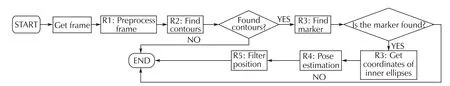
Fig.8 High level flow chart.
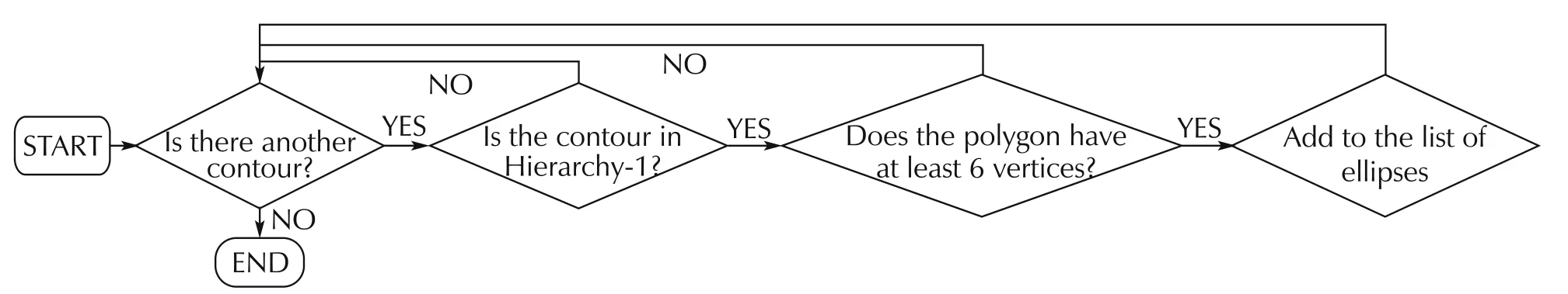
Fig.9 Find contours algorithms flow chart.
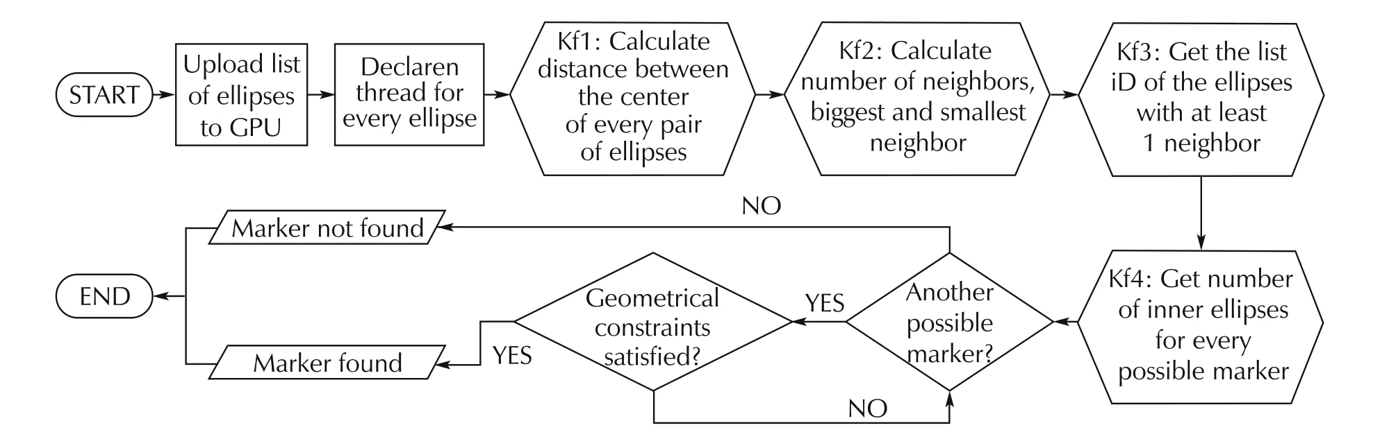
Fig.10 GPU-based find marker algorithm flow chart.
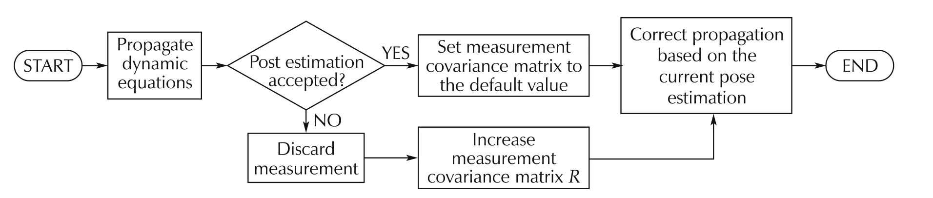
Fig.11 Pose filtering algorithm flow chart.
4.1 Marker detection on GPU
The detection of the marker is composed by two different stages:search of the main structure of the marker and detection of inner ellipses.The input of the GPU-based marker detection routine is the list of all the ellipses found in the current frame.The marker detection algorithm on the GPU is composed by 5 steps described as follows.
4.1.1 Detection of the main structure of the marker
The detection of the main structure of the marker is carried out using a dedicated GPU kernel function.The GPU kernel will search all the sets of concentric ellipses evaluating all the possible combinations between the ellipses provided as input.Each set of concentric ellipses,found during this step,is labeled as a possible marker and will be further processed in the next step of the algorithm,described below.The evaluation of all the possible combinations is carried out on the GPU declaring a number of threads equal to the square of the number n of ellipses found(n2),as described on Algorithm 1 in pseudo-code.It is worth mentioning that all the steps of the algorithm for marker detection are carried out using the same location of GPU memory,without transferring data from the GPU memory to the CPU memory and vice versa.
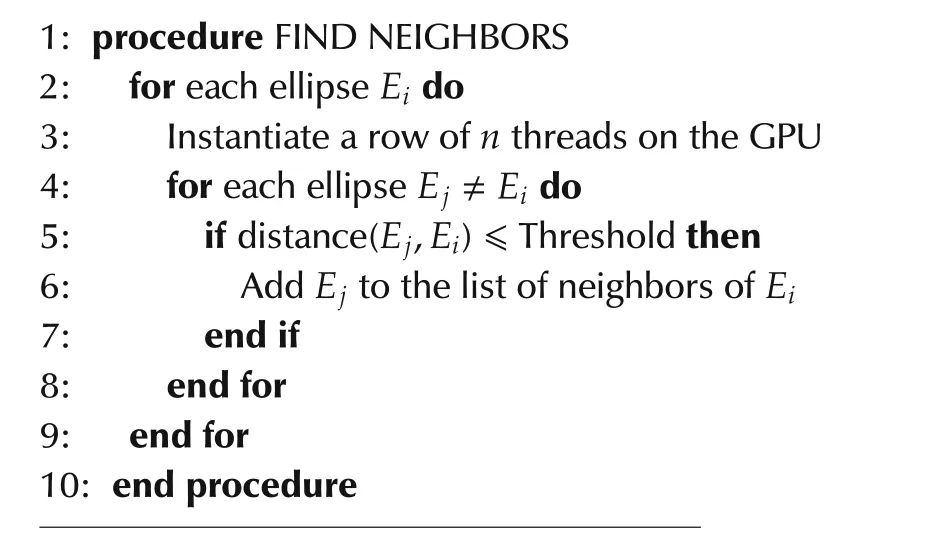
Algorithm 1(List of neighbors for every ellipse)
All the operations use pointers to the same memory,avoiding the creation of temporary copies of the initial set of data.The distance between two ellipses is calculated as the euclidean distance between their centers,expressed in pixel coordinates.The threshold has been determined experimentally.
In the GPUkernelfunction,each comparison between the generic ellipse Eiand the ellipse Ejis carried out by a dedicated thread.Therefore,all the comparisons between all the ellipses are made simultaneously:no for loops are required to make all the comparisons.The output of this kernel function is a matrix where for each ellipse Ei,a list of all the ellipses concentric with Eiis encoded.We will refer to the concentric ellipses with Eias neighbors of ellipse Ei.Every ellipse is concentric with itself.Furthermore if the ellipse Eiis concentric with Ej,then the converse is also true.This leads to a symmetric matrix.If a pair of ellipses(Ei,Ej)are concentric,a 1 will be stored in the position(i,j),otherwise a 0 will be stored.
The output of this routine is the list of all sets of concentric ellipse candidates to be possible markers.Each row of this matrix with a number of elements set to 1 greater than 2 describes a possible marker.This list will be provided in input to the second stage of the algorithm,in order to detect the real marker and estimate the pose of the helicopter.
4.1.2 Detection of the inner ellipses of the marker
In order to detect the inner ellipses for every possible marker,we first estimate the area on which the inner ellipses should be present.This is done detecting for every ellipse Eithe neighbor with the smallest and the biggest area.Since those ellipses are concentric(as determined by the previous phase),the center of every inner ellipse,if present,must be contained in the area bounded by these two ellipses.The search of the smallest and biggest ellipse corresponds to the search of the ellipses with the minimum and the maximum area.The search of maximum and minimum of a vector in a GPU kernel can be easily carried out using the reduction algorithm[23].After the detection of the smallest and biggest area,the algorithm proceeds counting the number of inner ellipses for every set of concentric ellipses.At this stage,only one set of ellipses should contain 4 inner ellipses.The typical output of this stage will be one set of ellipses corresponding to the marker.This phase is also implemented on the GPU in a way similar to the one described in Section 4.1.1.
4.1.3 Orientation of the inner ellipses
From the marker candidate produced as output of the previous routine,the algorithm starts evaluating the orientation of the 4 inner ellipses.In order to estimate the orientation,the algorithm searches for the inner ellipse with the biggest area,and then continues searching for the remaining 3 inner ellipses.The position of the three inner ellipses is predicted using the coordinates of the center of the marker and the coordinates of the center of the biggest ellipse.Then,the algorithm scan the list of inner ellipses,looking for the one with the center closer to the predicted position,as described from Algorithm 2 in pseudo-code.
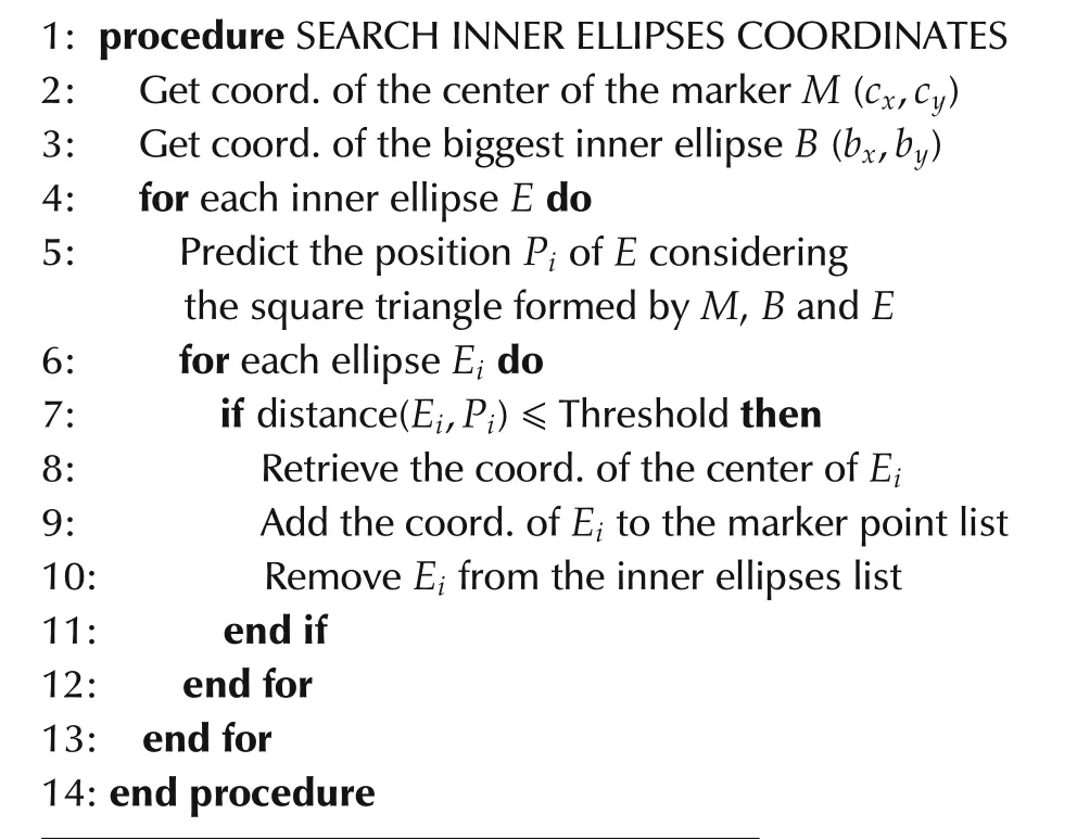
Algorithm 2(Search of the inner ellipses)
The different dimension of the inner ellipses is necessary in order to make the marker asymmetric and estimate not only the position of the camera w.r.t.to the center of the marker but also its orientation(in terms of roll,pitch and yaw angles).
4.1.4 Detection of outer/inner marker
A simple algorithm based on the color of the center of the biggest inner ellipse is used in order to detect the outer/inner marker(see Algorithm 3).
In order to have a transition from the outer marker to the inner marker and viceversa,the algorithm must detect the new condition for at least 10 consecutive frames.
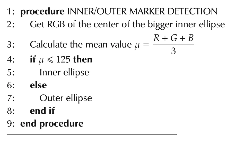
Algorithm 3(Detection of outer/inner marker)
4.2 Pose estimation
The pose estimation is carried out by comparing the coordinates of the centers of the inner ellipses with the information provided in input of the algorithm.The comparison is carried out through the GPU-based function solvePnP Ransac,available as part of the OpenCV libraries.The output of this function is the current pose of the camera w.r.t to the center of the marker.The solvePnPRansac function is based on the pinhole camera model[24].In this model,each point of the view is formed by projecting each image point into the corresponding image plane point using the perspective transformation sm=A[R|t]M where the matrix A contains the coefficients(cx,cy)and(fx,fy)representing respectively the coordinates of the principal point,that is usually at the image center,and the focal lengths expressed in pixel units.These coefficients are estimated experimentally through the calibration procedure of the camera.The matrix[R|t]is used to describe the camera pose w.r.t.to a static scene.The pose estimation is carried out by comparing the estimated coordinates of the centers of the inner ellipses in the camera reference frame with the known coordinates of the same ellipses in the world reference frame(with origin in the center for the marker).Fig.12 shows the reference system(NED)used for expressing the pose of the helicopter with respect to the center of the marker.
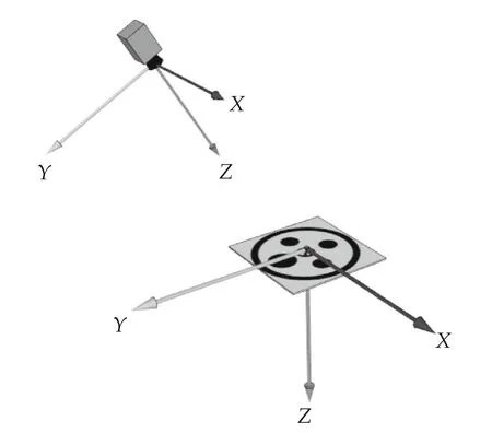
Fig.12 Reference system used for the pose estimation system based on NED(North-east-down)representation.
4.3 Pose estimation filtering
The output of the algorithm is filtered using a discrete extended Kalman filter in order to reduce the noise on the pose estimation when the camera is subject to vibrations and provide an estimation of the pose when the camera is occluded.The state vector is represented by the pose and velocity of the camera w.r.t.the marker(equation(1)):
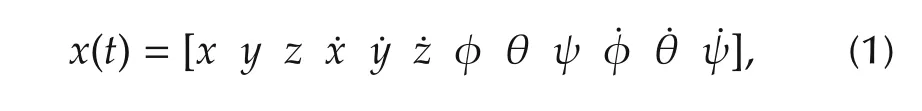
where(x,y,z)represents the translation of the camera and(φ,θ,ψ)represents the attitude.The states(x,y,z,φ,θ,ψ)are observable.
The covariance measurement matrix has been evaluated experimentally through static measurements:an extended data acquisition with the camera standing on a fixed point above the marker(using the xFrame machine,described in[21])has been performed.The variance of each measurement has been evaluated and used as the default value for the corresponding state variable(equation(2)):
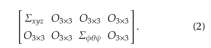
The triadrepresents the variance of the position of the camera along x,y and z axes whileis the variance of the roll,pitch and yaw angles respectively.The estimated variance for the six observable state variables is σ2=(0.01)2mm2.When the marker is not detected or the pose estimation is discarded,the diagonal elements of the R matrix are increased by a constant k,σ2=k× (0.01)2mm2,where k=100(this value has been chosen experimentally).When the marker is detected,the diagonal elements are setto their defaultvalue(see Fig.11).Themeasurements used in the Kalman filter are expressed in the world reference frame(origin in the center of the marker).
5 Field evaluation
In this section,we describe the results obtained while testing the pose estimation system for the autonomous landing task.An extensive laboratory evaluation has been carried out before testing our algorithm on a real system.The results of the laboratory evaluation are described in detail in our previous paper[21].The autonomous landing is performed in an indoor environment in order to test the effectiveness of the proposed system when the GPS is not available.
The tests are focused on the autonomous landing only:after the manual takeoff,the system is switched to autonomous mode.The hovering and the landing phase are carried-out autonomously,without any intervention of the pilot.The experimental setup is composed by a landing pad mounted on amobi leself-leveling robot and the quad rotor shown in Figs.5 and 65A video of the field tests can be found at the following link:https://www.youtube.com/watch?v=rBtXPDjK_QE.
5.1 Hovering
In this section,we shows the results obtained while testing the autonomous hovering.The hovering mode is designed in order to keep the center of the camera aligned with the center of the marker at 1.5 meters of altitude.Because of the limited view of the lensused,the test of hovering is performed with the quad rotor close to the hovering point.The purpose of this experiment is mainly focused on evaluating the capability of the quadrotor to remain on the desired position(with few cent imiters of errors)without the use of GPS.Figs.13–15 shows respectively the position of the quad rotor during the hovering test.After the manual take-off(from t=0s to t=35s)the control system is switched to autonomous mode.The quadrotor,then,moves to and keeps the desired position(x,y,z)=(0,0,1.5)using the vision system as only position measurement.The maximum error on x and y axes is below 10cm.Concerning the z axis,themaximum steady-error isalso around than 10 cm.
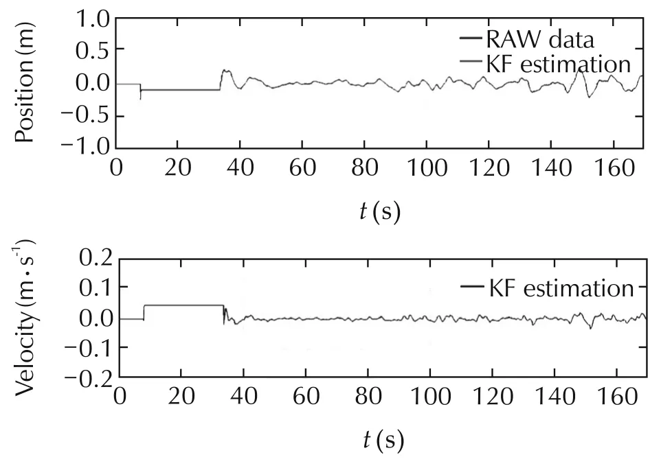
Fig.13 Position along x axis during the autonomous hovering.
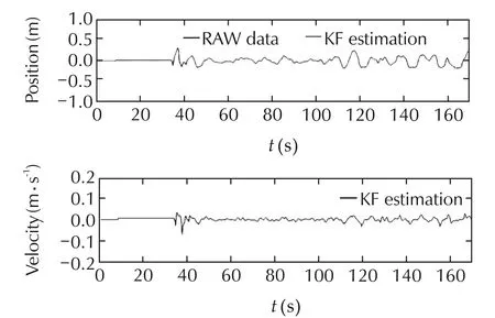
Fig.14 Position along y axis during the autonomous hovering.
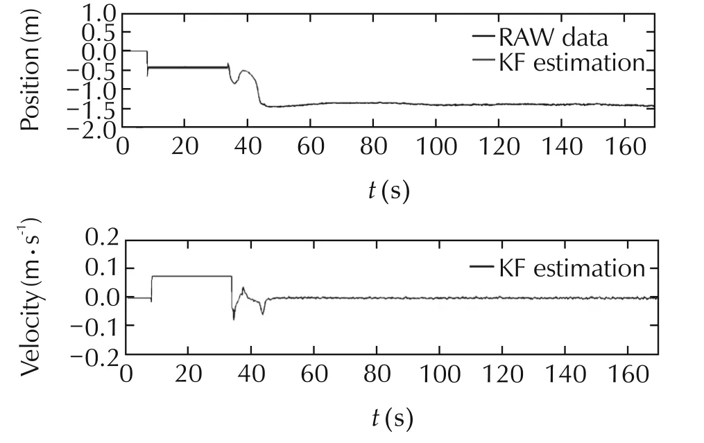
Fig.15 Position along z axis during the autonomous hovering.
5.2 Autonomous landing
In this section,we show the results obtained during the autonomous landing.The autopilot is programmed to autonomously land the quadrotor after 10 seconds of hovering if the error remains below 15cm for all the hovering procedure.After 10 seconds of hovering,the altitude set-point is decreased gradually until 0.5 meters.During the descending phase,the autopilot keeps controlling also the x and y position,assuring that the camera is always aligned with the center of the marker.For the last phase of the autonomous landing,from 0.5 meters to touch down,the quadrotor decrease gradually the propeller rotation until landing on the platform(see Figs.16–18).
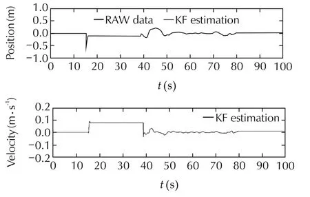
Fig.16 Position along x axis during the autonomous landing.
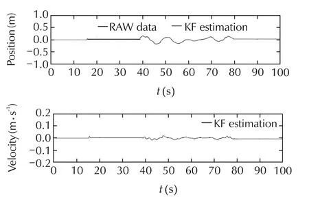
Fig.17 Position along y axis during the autonomous landing.
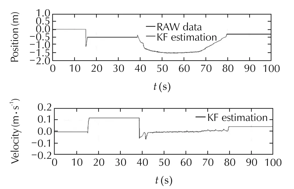
Fig.18 Position along z axis during the autonomous landing.
6 On-going and future work
The proposed algorithm for the pose estimation has been successfully tested using a small-scale quadrotor.A new version of the autonomous landing system based on an electric helicopter is under finalization.The goal is to prove the validity of the proposed approach with both types of rotary wing UAVs.
Anew version of the algorithm based on sensor fusion between GPS,IMUand vision dataiscurrently under development.Furthermore,the current algorithm for pose estimation is based on a custom fiducial marker.However,the overall architecture of the code can be adapted in order to detect different marker,such as the classical helipad.Concerning the software,additional work will be focused on investigating a theoretical approach in order to develop a GPU-based contour finding algorithm.
Our algorithm has been tested using the development board of Tegra TK1 system-on-chip(SOC)(www.nvidia.com/object/jetson-tk1-embedded-dev-kit).The current solution represents a proof-of-concept before porting our algorithm on a custom-board based on the same SOC.The custom-board will reduce drastically the weight of the hardware needed for processing while keeping the same performances.
The current system based on a high-frame rate USB 3 camera and Jetson TK1 board for on-board image processing will be extended with a dedicated 9 DOF IMU and Real-time kinematics GPS(RTK-GPS)(see Fig.19).The RTK-GPS allows to estimate the position of the helicopter with an accuracy of around 2 cm.The differential GPS correction are based on a ground GPS antenna with which the helicopter communicates exploiting a 915 MHz telemetry.The main purpose of the differential GPS will be to measure the accuracy of the proposed system in outdoor environments.
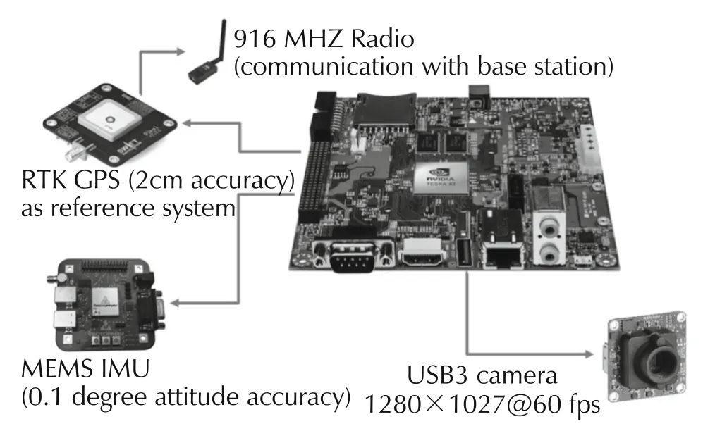
Fig.19 Block diagram of the pose estimation system for electric helicopter.
Fig.20 shows a picture of the helicopter under development.
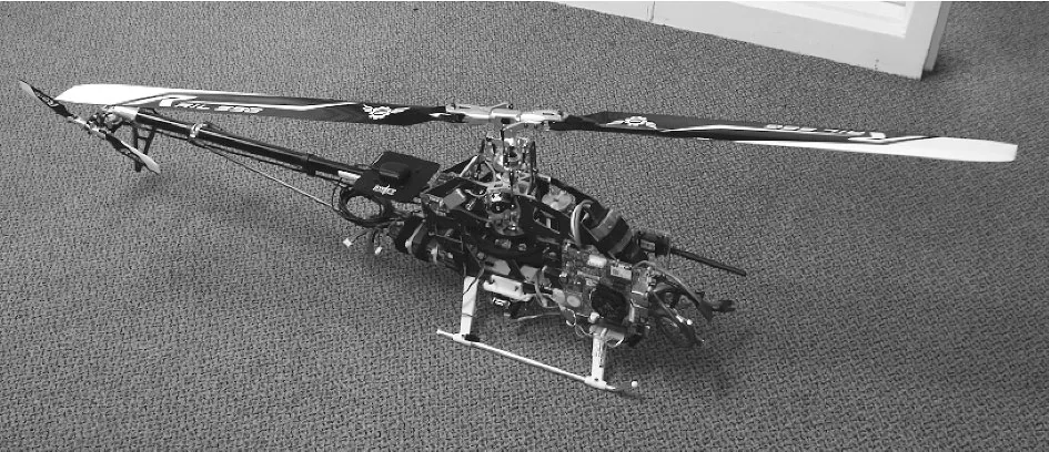
Fig.20 Electric helicopter(Synergy E5)equipped with the vision-based pose estimation system proposed in this paper.
The system is enhanced with RTK GPS and a 9 DOF inertial measurement unit.On the left nose of the helicopter the Jetson TK1 board is visible.The 9 DOF is mounted on the bottom of the helicopter.The z axis of the IMU is aligned with the rotor axis.The GPS antenna is placed right behind the body of the helicopter,while the GPS module is places on the rudder,in order to avoid interference between the GPS module and the USB3 camera.The lever-arm between the GPS,the IMU and the vision system is taken into account.
7 Conclusions
The obtained results show that the proposed algorithm is able to provide accurate pose estimation with a minimum framerate of 30 fps and an image dimension of 640×480 pixels with error less than 8%of the marker diameter,allowing for autonomous takeoff and landing.The possibility to use a frame dimension of 640×480 allows the system to detect the complex landing markers even from greater distances.The system is able to perform autonomous landing in indoor environment,exploiting the camera as the only position sensor.Concerning the vision-based based pose estimation system,the time required only by the GPU-computation is around 3 ms,regardless of the complexity of the image.This allows the possibility to provide an estimate of the maximum time required by the pose estimation estimation system.
[1]C.Bu,Y.Ai,H.Du.Vision-based autonomous landing for rotorcraft unmanned aerial vehicle.IEEE International Conference on Vehicular Electronics and Safety(ICVES),Beijing:IEEE,2016:1–6.DOI 10.1109/ICVES.2016.7548174.
[2]A.Gautam,P.B.Sujit,S.Saripalli.Asurvey of autonomouslanding techniques for UAVs.International Conference on Unmanned Aircraft Systems(ICUAS),Orlando:IEEE,2014:1210–1218.DOI 10.1109/ICUAS.2014.6842377.
[3]M.F.R.Lee,S.F.Su,J.W.E.Yeah,et al.Autonomous landing system for aerial mobile robot cooperation.The Joint 7th International Conference on Soft Computing and Intelligent Systems(SCIS)and 15th International Symposium on Advanced Intelligent Systems(ISIS),Kitakyushu:IEEE,2014:1306–1311.DOI 10.1109/SCIS-ISIS.2014.7044826.
[4]X.Guan,H.Bai.AGPU accelerated real-time self-contained visual navigation system for UAVs.IEEE International Conference on Information and Automation,Shenyang:IEEE,2012:578–581.DOI 10.1109/ICInfA.2012.6246879.
[5]S.Yang,S.A.Scherer,K.Schauwecker,et al.Onboard monocular vision for landing of an MAV on a landing site specified by a single reference image.International Conference on Unmanned Aircraft Systems(ICUAS),Atlanta:IEEE,2013:318–325.DOI 10.1109/ICUAS.2013.6564704.
[6]S.Yang,S.A.Scherer,K.Schauwecker,A.Zell.Autonomous Landing of MAVs on an arbitrarily textured landing site using onboard monocular vision.Journal of Intelligent&Robotic Systems,2014,74(1/2):27–43.
[7]G.Klein,D.Murray.Parallel tracking and mapping for small AR workspaces.The 6th IEEE and ACM International Symposium on Mixed and Augmented Reality,Nara:IEEE,2007:225–234.DOI 10.1109/ISMAR.2007.4538852.
[8]F.Cocchioni,A.Mancini,S.Longhi.Autonomous navigation,landing and recharge of a quadrotor using artificial vision.International Conference on Unmanned Aircraft Systems(ICUAS),Orlando:IEEE,2014:418–429.DOI 10.1109/ICUAS.2014.6842282.
[9]Y.Jung,D.Lee,H.Bang.Study on ellipse fitting problem for vision-based autonomous landing of an UAV.The 14th International Conference on Control,Automation and Systems(ICCAS),Seoul:IEEE,2014:1631–1634.DOI 10.1109/ICCAS.2014.6987819
[10]K.Li,P.Liu,T.Pang,et al.Development of an unmanned aerial vehicle for rooftop landing and surveillance.International Conference on Unmanned Aircraft Systems(ICUAS),Denver:IEEE,2015:832–838.DOI 10.1109/ICUAS.2015.7152368.
[11]A.Masselli,S.Yang,K.E.Wenzel,et al.A cross-platform comparison of visual marker based approaches for autonomous flight of quadrocopters.International Conference on Unmanned Aircraft Systems(ICUAS),Atlanta:IEEE,2013:685–693.DOI 10.1109/ICUAS.2013.6564749.
[12]W.Roozing,A.H.Goktogan.Low-cost vision-based 6-DOF MAV localization using IRbeacons.IEEE/ASME International Conference on Advanced Intelligent Mechatronics,Wollongong:IEEE,2013:1003–1009.DOI 10.1109/AIM.2013.6584225.
[13]H.Cheng,Y.Chen,X.Li,et al.Autonomous takeoff,tracking and landing of a UAV on a moving UGV using onboard monocular vision.Proceedings of the 32nd Chinese Control Conference,Xi’an:IEEE,2013:5895 – 5901.
[14]S.Lange,N.Sunderhauf,P.Protzel.A vision based onboard approach for landing and position control of an autonomous multirotor UAV in GPS-denied environments.International Conference on Advanced Robotics,Munich,2009:1–6.
[15]K.H.Hsia,S.F.Lien,J.P.Su.Height estimation via stereo vision system for unmanned helicopter autonomous landing.International Symposium on Computer,Communication,Control and Automation(3CA),Tainan:IEEE,2010:257–260.DOI 10.1109/3CA.2010.5533535.
[16]S.Saripalli,G.S.Sukhatme.Landing on a moving target using an autonomous helicopter.Field and Service Robotics:Recent Advances in Research and Applications.Berlin:Springer,2006:277–286.DOI 10.1007/10991459_27.
[17]D.Jeon,D.-H.Kim,Y.-G.Ha,et al.Image processing acceleration for intelligent unmanned aerial vehicle on mobile GPU.Soft Computing,2016,20(5):1713–1720.DOI http://dx.doi.org/10.1007/s00500-015-1656-y.
[18]F.Ababsa,M.Mallem.A robust circular fiducial detection technique and real-time 3D camera tracking.Journal of Multimedia,2008,3(4):34–41
[19]L.Calvet,P.Gurdjos,V.Charvillat.Camera tracking using concentric circle markers:Paradigms and algorithms.The 19th IEEE International Conference on Image Processing,Orlando:IEEE,2012:1361–1364.DOI 10.1109/ICIP.2012.6467121.
[20]F.Ababsa,M.Mallem.A robust circular fiducial detection technique and real-time 3D camera tracking.Journal of Multimedia,2008,3(4):34–41.
[21]A.Benini,M.J.Rutherford,K.P.Valavanis.Real-time,GPU-based pose estimation of a UAV for autonomous takeoff and landing.IEEE International Conference on Robotics and Automation(ICRA),Stockholm:IEEE,2016:3463–3470.DOI 10.1109/ICRA.2016.7487525.
[22]S.A.Conyers,N.I.Vitzilaios,M.J.Rutherford,et al.A mobile self-leveling landing platform for VTOL UAVs.IEEE International Conference on Robotics and Automation(ICRA),Seattle:IEEE,2015:815–822.DOI 10.1109/ICRA.2015.7139272.
[23]CUDA Programming Guide:http://docs.nvidia.com/cuda/cuda-cprogramming-guide.
[24]Pinhole Camera Model:https://docs.opencv.org/2.4/modules/calib3d/doc/camera_calibration_and_3d_reconstruction.html.
 Control Theory and Technology2018年2期
- Control Theory and Technology的其它文章
- Nonlinear robust control of a quadrotor helicopter with finite time convergence
- Ranging-aided relative navigation of multi-platforms
- Consensus controller for multi-UAV navigation
- Distributed output feedback stationary consensus of multi-vehicle systems in unknown environments
- Flocking control of a fleet of unmanned aerial vehicles
- Special issue on unmanned aerial vehicles(UAVs)