Innovation and Practice of Hard Rock TBM in China
2018-05-10 09:17:58HONGKairongWANGDujuanGUORujun51158500015001661171
隧道建设(中英文) 2018年4期
HONG Kairong, WANG Dujuan, GUO Rujun(1. ., ., 51158, , ;2. , 50001, , ;. ., ., 50016, , ;. ., ., 61171, , )
0 Introduction
The hard rock tunnel boring machine (TBM) is characterized by high efficiency, good tunnel contour, little impact on surroundings, etc., hence, it is particularly suitable for the construction of deep long tunnels. The method has been successfully applied to the construction of tunnels in the fields of energy, transportation, water conservancy, national defense, etc. in many countries, such as the completed Lesotho South-to-North Water Diversion Project[1], the Channel Tunnel[2]and the Vereina Tunnel[3]. Some manufacturers, such as Robbins (USA), Herrenknecht AG (Germany), and CMC (Italy), have already had relatively complete sets of TBM design, manufacturing and application technologies; while, compared with the relatively well-developed technologies abroad, there is still a way for China′s R&D and engineering application of TBMs to go on[4-5]. For tunneling under complex geological conditions, some TBM manufacturers in China have made valuable exploration in the design of tunneling solutions for weak surrounding rock deformation, fractured fault zone, high ground stress, high rock temperature, rock burst, high-pressure confined water, gushing water, and many other unfavorable geological conditions[6-11], and have made some progresses and bottleneck broken through considering our long duration of dependence on foreign supplies and joint manufacturing.
China has already been known as the country with the largest tunnel construction scale and the fastest tunnel construction development speed in the world, as well as the county with the highest difficulty in tunnel construction due to the complex geological conditions in mountainous areas. In the next few years, China is going to build a large number of railway tunnels in the central and western regions, and more frequently TBMs will be utilized. At present, TBM is still considered poor design for dealing with unfavorable geological conditions, and has the disadvantages such as passive (or lagging) treatment, slow response, complex manual operations, and delaying construction period. Furthermore, it is difficult to perform advance geological prediction and to adopt assistant construction methods timely and effectively. In case of unexpected unfavorable geological conditions, problems such as jamming are likely to occur, which affects the efficiency of TBM tunneling and may even result in major safety accidents. The conventional TBMs suffer from fixed structure model, and thus the shortcomings such as small space for support operation of TBM main body, mutual interference of various processes, complex material transportation system, and low reliability, seriously restrict the efficiency of TBM tunneling. When TBMs are applied to the construction under complex geological conditions, in order to solve the problems such as high ground temperature, high rock burst, and mud outburst & gushing water, we need to conduct relevant research on how to further increase the material transportation efficiency of TBM and improve the adaptability of TBM to complex strata.
Based on the complex geological conditions of Gaoligongshan Tunnel on Dali-Ruili Railway, i.e. high ground temperature, high ground stress, and high seismic intensity, as well as active neotectonic movement, active geothermal water environment, active externally-driven geological conditions, and active bank slope surface reconstruction, and the existing equipment performance, the study and manufacturing work of TBM is carried out from the aspects of high efficiency rock breaking, TBM over-excavation design, support system design and advance geological prediction, so as to enhance the TBM integration technology, overcome the technical problem concerning the best matching of design performance and tunneling parameters, and achieve a further leap of TBM.
1 Analysis of state-of-art of TBM research and application
1.1 Analysis of stat-of-art of TBM research and application in China and abroad
1.1.1 TBM research and application abroad
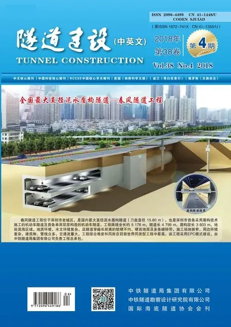
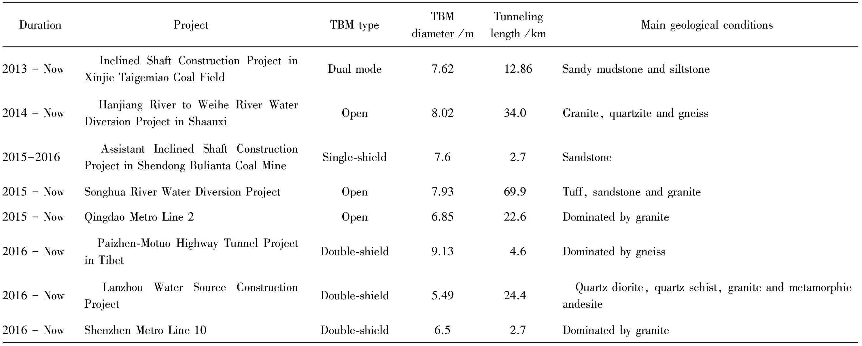
In 1851, the world′s first TBM that could be used for continuous tunneling was designed by Charles Wilson, an American engineer. However, due to the fact that the rock breaking-related problem was not solved effectively, the construction efficiency of TBM was hardly comparable to that of the drilling-blasting method, which thus left the TBM useless. In 1956, with the help of disc cutter technology, the rock breaking-related problems were successfully solved. Since then, TBMs have been widely promoted and utilized. The statistics of some representative TBM projects abroad are shown in Table 1. At present, foreign TBM technology has been relatively well developed. The main TBM manufacturers include Robbins, Wirth, Herrenknecht AG, Lovat, Komatsu, and so on.
1.1.2 Research on and application of TBM in China
China started TBM R&D in 1964, when Shanghai Investigation, Design & Research Institute Co., Ltd. (SIDRI) and Beijing Water Resources and Electric Power College (now North China University of Water Resources and Electric Power-NCWU) jointly conducted the conceptual design. In 1965, the development of TBM was listed as a national key scientific research project. A TBM with a diameter of 3.5 m was developed under the guide of SIDRI, and the corresponding industrial test (with the geological conditions for excavation being granitic gneiss and limestone, and the compressive strength being 100-240 MPa) was conducted at Xierhe Cascade Hydro-power Station Power Tunnel in Xiaguan Town, Yunnan, with a maximum monthly advance rate of 48.5 m.
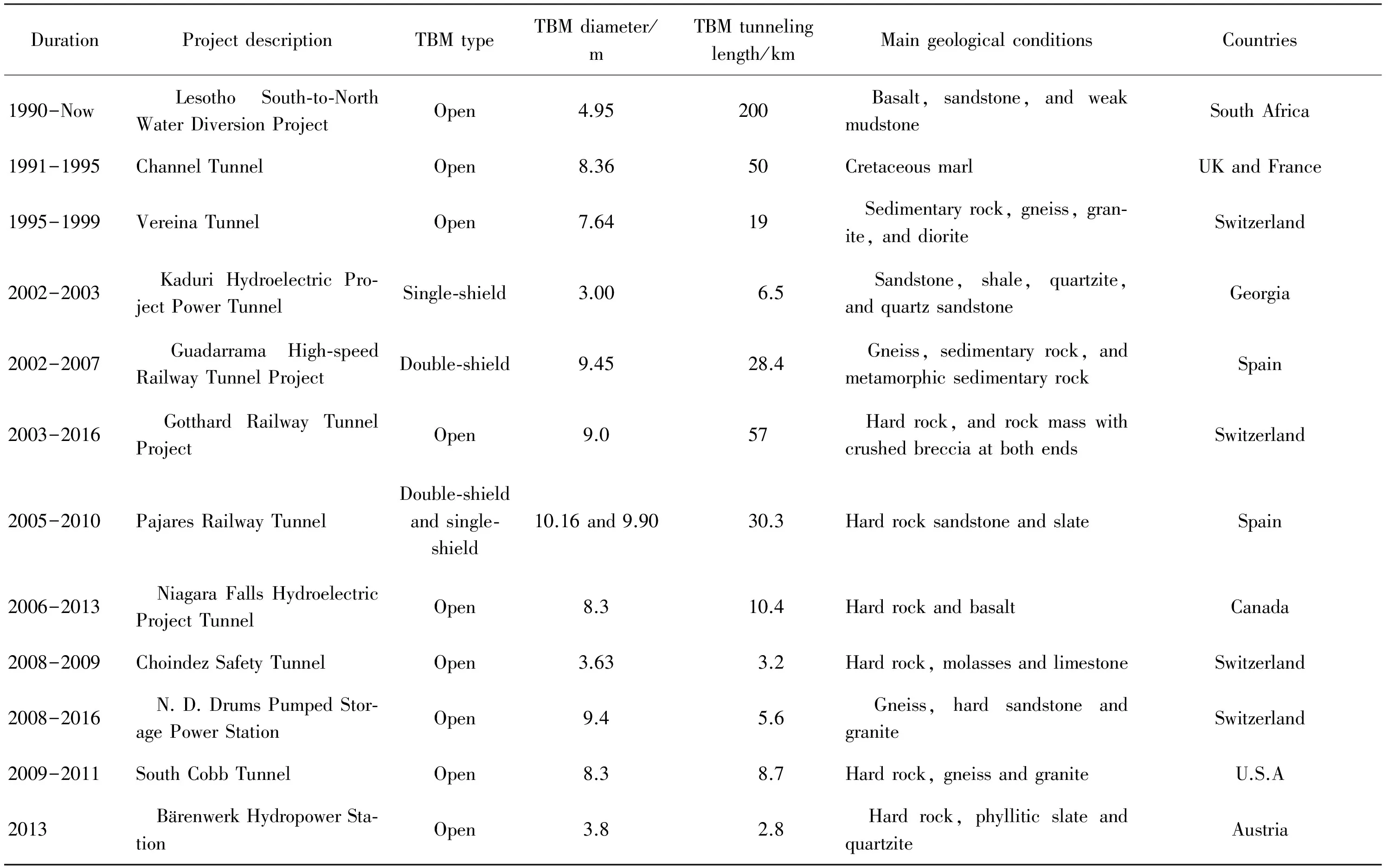
Table 1 Foreign typical TBM projects[12-15]
At the beginning of the 21st century, as one of the major technological equipments in the 16 fields prioritized to revitalize Chinese equipment manufacturing industry, the TBM industry faced unprecedented opportunities for development. China Railway Engineering Equipment Group Co., Ltd. and China Railway Construction Heavy Industry Co., Ltd. were founded at the right moment. Up to now, such companies have had strong capability for the design and manufacturing of TBM. In recent years, some Chinese companies have been relying on the National High-tech R&D Program ("863 Program") and the National Key Basic R&D Program ("973 Program") to carry out the independent research and development of TBM. The statistics of some achievements are shown in Table 2.
The typical cases of the application of TBM in construction of rock tunnels in China are shown in Table 3.
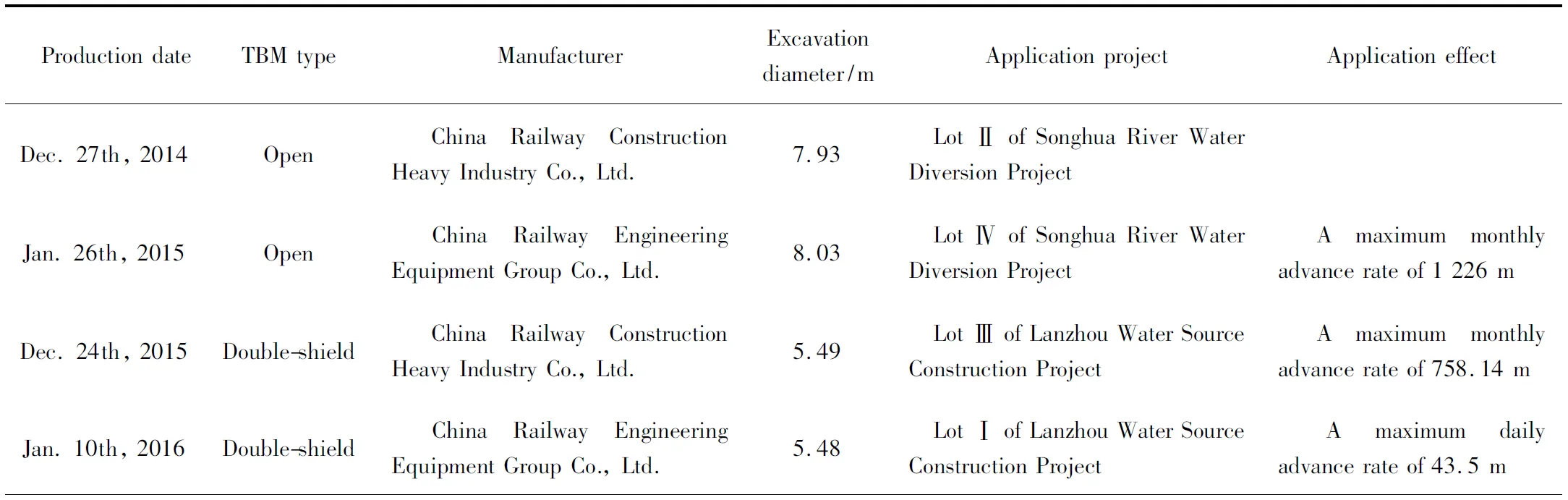
Table 2 Typical TBMs developed by Chinese companies [6,16-18]

Continued Table 2
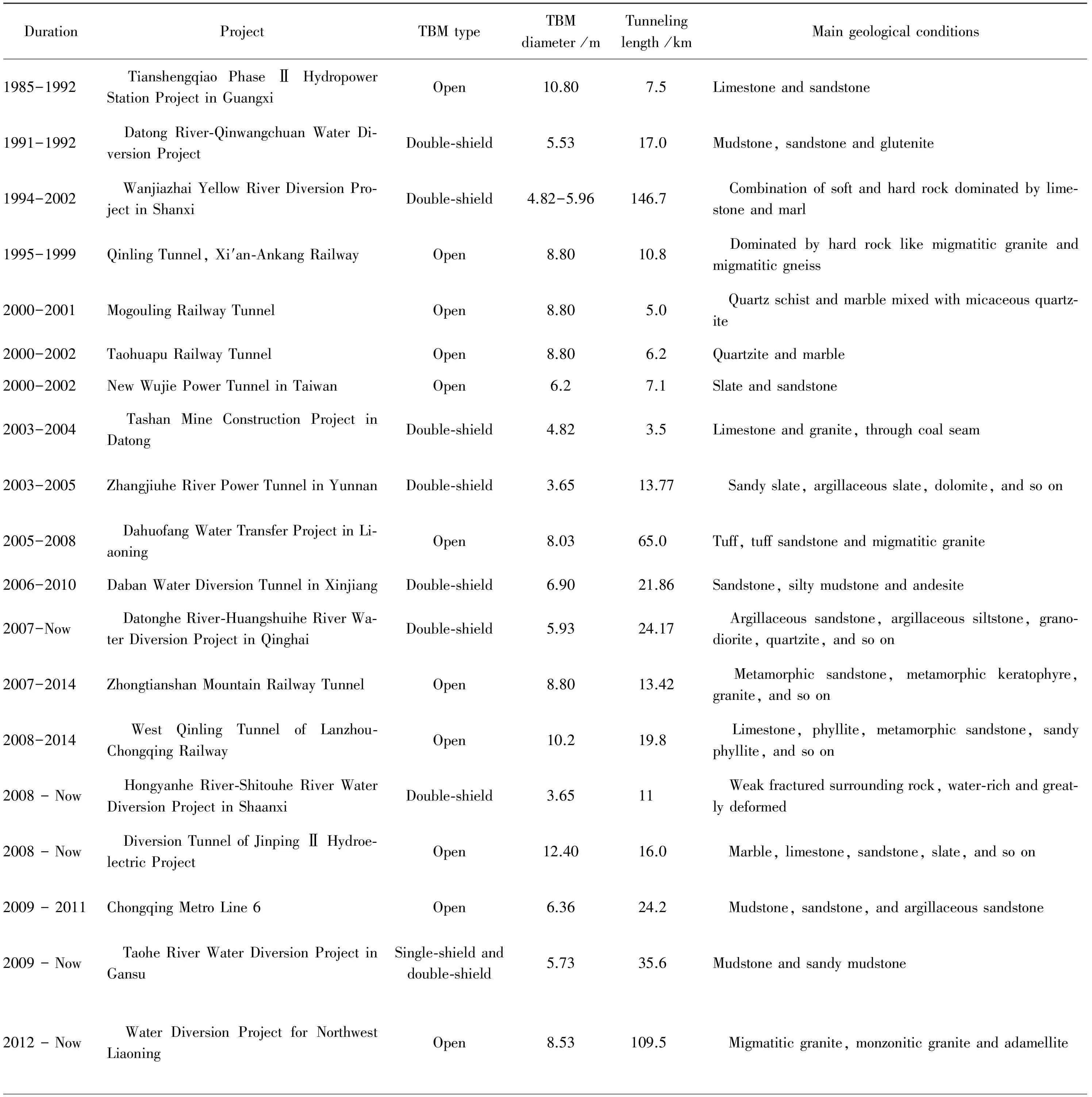
Table 3 Typical cases of application of TBM to construction of rock tunnels in China[19-24]
Continued Table 3
1.2 Analysis of state-of-art of research on key TBM technologies
1.2.1 State-of-art of research on TBM adaptability
In the past 20 years, TBM tunneling technologies have been rapidly developed in China. However, there is no national specification on TBM-based tunnel design and construction yet. In addition, China has a vast area and great differences in engineering geological conditions. Therefore, formulating a set of reasonable design philosophy and construction technology system featuring the good adaptability of TBM to ground characteristics has become a challenge for TBM design and tunnel construction development.
1.2.2 State-of-art of research on TBM tunneling technologies
In view of the challenge concerning TBM tunneling technologies under complex geological conditions, relevant organizations in China and abroad have conducted targeted researches and attempts, but there are still some problems to be solved, such as prevention and control of rock burst and gushing water: (1) The prevention and control of rock burst during TBM tunneling are still in the exploratory stage. The rock burst level can only be roughly predicted, and it is difficult to accurately predict the time and location of occurrence of rock burst; with regard to the control of medium or higher-level rock burst, there is a lack of scientific theoretical guidance in respect of the timing and solution selection[25]; for strong or extremely strong rock burst, the resulted damage can only be mitigated through corresponding supporting measures, and it is hard to effectively control such burst; (2) TBM tunneling in water-rich ground is very risky, and it is difficult to effectively deal with such risk; at the same time, there is a risk that TBM may be sunk, submerged, or buried in water-bearing loose ground due to the mud burst or gushing water. The technical measures in respect of geological prediction, advance treatment, drainage, water stopping and so on for tunnel-related water gush mostly originate from experience, that is to say, there is a lack of corresponding theoretical guidance; it is hard to achieve good combination of equipment allocation, technology and TBM, and the implementation effect is not satisfactory.
1.2.3 State-of-art of research on advance geological prediction
Methods of advance geological prediction for tunnel construction can be classified into two categories, i. e. geological method and geophysical method[26]. During the drilling-blasting-based tunnel construction, the prediction technology for unfavorable geologic bodies ahead of the working face is relatively proven. Because of the structure and construction method characteristics of TBM, many conventional geological prediction methods cannot be used or are greatly restricted in tunnels constructed by TBM. Therefore, the advance geological prediction system for TBM tunneling still needs further development and improvement.
1.3 Typical cases of TBM tunneling projects
1.3.1 TBM tunneling in fractured fault zones and weak surrounding rock sections
1.3.1.1 Diversion Tunnel of Nabang Hydropower Station in Yunnan
The excavation diameter of the tunnel is 4.5 m, the length is 9.8 km, and the open TBM manufactured by Herrenknecht AG is used for construction. There the rock is dominated by gneiss, and large faults and gushing water exist. The section is characterized by the alternation of extremely hard rock and weak alteration belt. The construction of this project encounters high cutter wearing, cutterhead weld cracking, plastic deformation of cutter holder positioning surface, jamming caused by surrounding rock deformation in weak alteration belts, gripper failing to support the movement forward, and other technical problems.
1.3.1.2 Countermeasures and construction result
In the initial stage of TBM design, an emergency shotcreting system connected to the back-up shotcreting system of the TBM was designed and arranged; by utilizing the delivery pump of the back-up shotcreting system, the concrete was directly transported via the pipeline transferring joints to the front of the TBM main body for concrete casting. During passing through the weak surrounding rock in alteration belts, the distance of about 10 m from the gripper to the shield tail of open TBM was utilized to timely erect steel arches with short intervals and cast early-strength concrete at places where the shield had just emerged. In this way, the TBM successfully passed through six sections of weak surrounding rock in alteration belts with a total length of about 500 m. For weak and deformed surrounding rock, the following technical countermeasures may be considered.
(1)Appropriate TBM shall be selected. If shielded TBM is used, the diameter of the shield shall be reduced stepwise from the front to the rear, the length of the shield shall be shortened as much as possible, and the thrust capacity shall be enhanced.
(2)In order to cope with the large deformation of surrounding rock, the TBM over-excavation design shall be considered. In the case of over-excavation diameter ≤ 100 mm, the technical solution of stretching the gauge cutter cushion block outward shall be adopted; in the case of over-excavation diameter > 100 mm, the technical solution of "cutterhead lifting system + reservation of gauge cutter holder + outward-stretching of gauge cutter cushion block "or" replacement of cutterhead gauge cutter block + modification of shield" shall be adopted.
(3)With respect to the new type of support design and protection design, the flexible water-expansion anchor bolt support, flexible steel arch support, semi-mechanized emergency shotcreting system, and continuously closed "rebar panel supporting system" may be adopted according to the actual conditions.
1.3.2 TBM tunneling in surrounding rock sections with strong rock burst
So far, the finished TBM tunneling projects featuring typical rock burst in China include the Qinling Tunnel of Xi′an-Ankang Railway and the Diversion Tunnel of Jinping Ⅱ Hydroelectric Project, etc.; those under construction include the ABH Water-conveyance Tunnel Project in Xinjiang, the Hanjiang River to Weihe River Water Diversion Project in Shaanxi and the Gaoligongshan Tunnel on Dali-Ruili Railway, etc[27-29]. For surrounding rock sections with strong rock burst, the following technical countermeasures may be considered.
(1)For medium or less-strong rock burst: The equipment of open TBM may be based on to adopt the wiremesh, anchor bolt, steel arch, and shotcreting, or the combined flexible anchor bolt, flexible steel arch, and rebar panel support; as long as proper control is carried out, the influence of rock burst on project construction may be greatly reduced.
(2)For extremely strong rock burst, due to the difficulty in accurate prediction and control in respect of time and location, at present, the influence of rock burst on project construction could only be reduced as far as possible by utilizing appropriate support techniques, pilot borehole and drilling-blasting-based pretreatment, etc.
(3)The micro-seismic monitoring technology shall be adopted to predict rock burst; the accumulation and summarization of more practical project experience shall be based on to systematically analyze the interrelationship among the conditions, time, location and impact of rock burst, so as to further improve the rock burst monitoring technology.
1.3.3 TBM tunneling in sections with mud burst and gushing water
Mud burst and gushing water have great influence on TBM tunneling. Currently, TBM tunneling projects suffering from severe mud burst and gushing water in China include the Qinling Tunnel of Hanjiang River to Weihe River Water Diversion Project, the Wanjiazhai Yellow River Diversion Project in Shanxi, the Jinping Ⅱ Hydroelectric Project and the Taohe River Water Diversion Project, etc. For sections with mud burst and gushing water, the following technical countermeasures may be considered.
(1)During tunneling upwards, the risk is generally controllable; according to the specific conditions of the projects, consideration may be given to the gravity drainage of the tunnel or the proper arrangement of drainage system and elevated transportation track.
(2)During tunneling downwards, the availability of the TBM declines, hence both the cost and the construction period increase, and the equipment may be submerged, that is to say, there is high risk. Therefore, it is recommended to provide super-strong drainage system in advance according to the survey and design data (it is necessary even if no heavy gushing water occur).
(3)For gushing water from fissures of relatively complete rock mass, the effect of advance grouting may be limited, hence the technical solution, "drainage + water stopping", should be adopted.
(4)In sections with gushing water from karst cave and weak, fractured and loose rock mass, water and/or mud burst(s) may occur, hence the TBM is very likely to be jammed. In this case, the TBM should pass through step by step after carrying out advance geological prediction and advance grouting or manual treatment.
(5)Some projects may require the use of dual-mode TBM (i.e., with the open TBM tunneling mode and the EPB (earth pressure balance) shield tunneling mode) for construction, where conversion between the two modes may be conducted according to the geological conditions.
2 Project overview
2.1 Overview of tunnel project
With a total length of 34.5 km, Gaoligongshan Tunnel on Dali-Ruili Railway is currently the first ultra-long single-track railway tunnel under construction in China. The geological conditions of the tunnel are complex. For the exit section of the tunnel, the main tunnel is constructed by large-diameter TBM, while the parallel adit is constructed by small-diameter TBM. The main tunnel is constructed by the largest-diameter TBM developed by Chinese engineers (namely, T "Caiyun", with an excavation diameter of 9.03 m), and the TBM tunneling began on January 6th, 2018; the parallel adit is constructed by the first re-manufactured TBM in China (namely, the TBM "Caiyun Ⅰ", with an excavation diameter of 6.39 m), and the TBM tunneling began on August 28th, 2017. The plan layout for construction of Gaoligongshan Tunnel is shown in Fig. 1.
2.2 Geological characteristics of tunnel sections constructed by TBM
In the exit section of Gaoligongshan Tunnel to be constructed by TBM, the ground surface is sporadically covered by the Quaternary Holocene landslide accumulation, colluvium and deluvium, alluvium and proluvium, deluvium and proluvium, deluvium, deluvium and eluvium, as well as the Upper Pleistocene alluvial-proluvial mollisol, silty clay, coarse sand, gravelly sand, fine-round (angular) gravel soil, coarse-round (angular) gravel soil, gravelly soil, cobbly soil, boulder soil, block stone soil, and other strata. The underlying ground include the Neogene and Yanshanian granite, unknown mixed granite, dolerite dyke, as well as fault angular gravel, crushed rock, and alterated rock of crushed fracture and fault zones of various periods, etc. The ground passed through by TBM tunneling are mainly composed of Yanshanian granite (8.81 km, 73%), schist, slate, phyllite mixed with quartzite, and metamorphic sandstone (1.44 km, 22%). The surrounding rock is mainly of Grade Ⅲ, but the proportion of Grade Ⅳ and Grade Ⅴ surrounding rock is as high as 40%. It is predicted that the normal volume of gushing water in the main tunnel is 12.77×10⁴m3/d and the maximum volume is 19.2×10⁴m3/d. The main parameters of surrounding rock of the tunnel sections constructed by TBM are shown in Table 4.
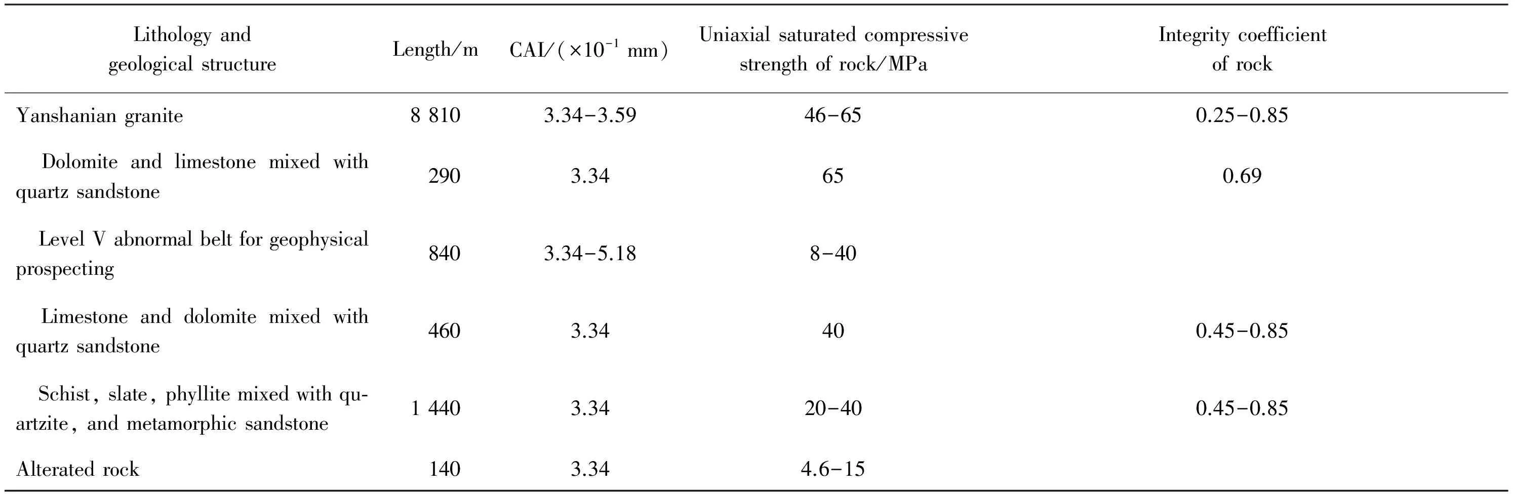
Table 4 Main parameters of surrounding rocks of tunnel sections constructed by TBM
2.3 Analysis of unfavorable geological conditions
The unfavorable geological conditions of TBM tunneling section of Gaoligongshan Tunnel mainly include high ground stress, fractured ground, high ground temperature, high seismic intensity, dissolvable rock and water gush, etc.
(1)High ground stress: The maximum cover of the tunnel is 1 155 m, and the regional stress field is relatively high. The relationship among the values of three-dimension principal stress around the tunnel body in the survey area is: vertical principal stress (about 31 MPa) > maximum horizontal principal stress (20-29 MPa) > minimum horizontal principal stress (13-19 MPa). The angle between the dominant direction of the maximum horizontal principal stress and the direction of the tunnel alignment is 12°-21°, and rock burst and large deformation of soft rock may occur to the tunnel. According to the prediction, the total length of soft rock large-deformation section of the main tunnel is 3 185 m, and the length of slight large-deformation section is 1 435 m; in fractured fault zones, local fault clay is prone to medium-large deformation, with a length of 1 750 m.
(2)Fractured ground: There will be 20 fractured-extremely fractured rock mass sections (with a total length of 1 280 m) in TBM tunneling section of main tunnel; there will be 15 fractured-extremely fractured rock mass sections (with a total length of 980 m) in TBM tunneling section of parallel adit. The proportion of Grade Ⅳ and Grade Ⅴ surrounding rock passed through by the whole tunnel is as high as 40%.
(3)High ground temperature: In mountain-crossing sections of Gaoligongshan Tunnel, the maximum temperature measured by deep hole drilling is 40.6 °C, the maximum temperature at the shoulder surface is 36.7 °C, and the temperature of the rock mass in tunnel body section D1K197+460~D1K207+582 (with a length of 10.122 km) is 28~39 °C[30].
(4)High seismic intensity: The area is located in the seismic zone of southwestern Yunnan, where the intensity of seismic activity is very high and the earthquake frequency is high. The seismic ground motion peak acceleration in the survey area is 0.20g, and the period of seismic ground motion response spectrum is 0.45 s. The correlation between the strong earthquakes and the distribution of the active faults is extremely high, and most of the strong earthquakes above Magnitude 6 are distributed along active faults. The site ever suffered strong earthquakes in the history. In May 1976, a 7.3-magnitude earthquake occurred in Longling.
(5)Dissolvable rock and water gush: In the entrance section of the tunnel, the total length of the Triassic dolomite and the sandwich-type dissolvable rock in Jurassic, Ordovician, Cambrian and other strata is 1 392 m, with the karst weakly-moderately developed. The Silurian limestone and dolomite in the middle of the tunnel are 590 m in length, and the Devonian limestone and dolomite in the exit section of the tunnel are 1 330 m in length, with the karst weakly developed.
3 Research on adaptability of key TBM parameters
3.1 Research on adaptability of rock-breaking and wearing parameters of TBM disc cutters
3.1.1 Research on adaptability of rock breaking of disc cutters
The arrangement of TBM cutters, especially the spacing between the cutters, is crucial to the rock breaking efficiency of TBM. A reasonable spacing between cutters has an important influence on the improvement of tunneling ability of TBM. Therefore, it is necessary to carry out the prototype disc cutter rock breaking experiment under different cutter spacing, to determine the reasonable cutter spacing with respect to the arrangement of TBM cutters, so as to provide reference for the design of TBM cutterhead.
3.1.1.1 Scheme of experiment on different cutter edge spacings
By using the TBM boring mode experimental platform (as shown in Fig. 2), the edge spacing of the disc cutters on the cutterhead was adjusted to 80 mm, 90 mm, 100 mm, 110 mm, 120 mm and 130 mm, respectively, and disc cutter rock breaking tests were carried out under 6 different cutter edge spacings.
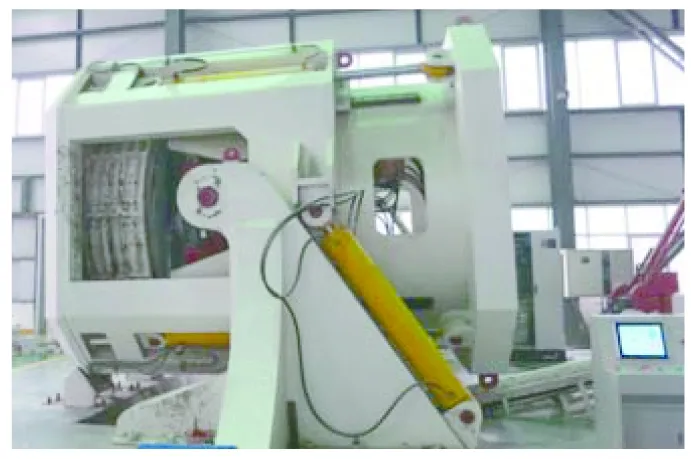
Fig. 2 TBM boring mode experimental platform
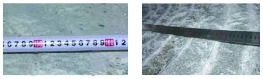
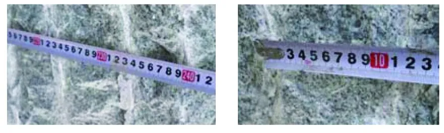
The rock sample used was granite. The rock sample was in the form as shown in Fig. 3. Four pieces (two pieces of each type) were processed and spliced respectively, with gaps in the middle filled with concrete. The rock used was granite with a strength of 180-190 MPa.
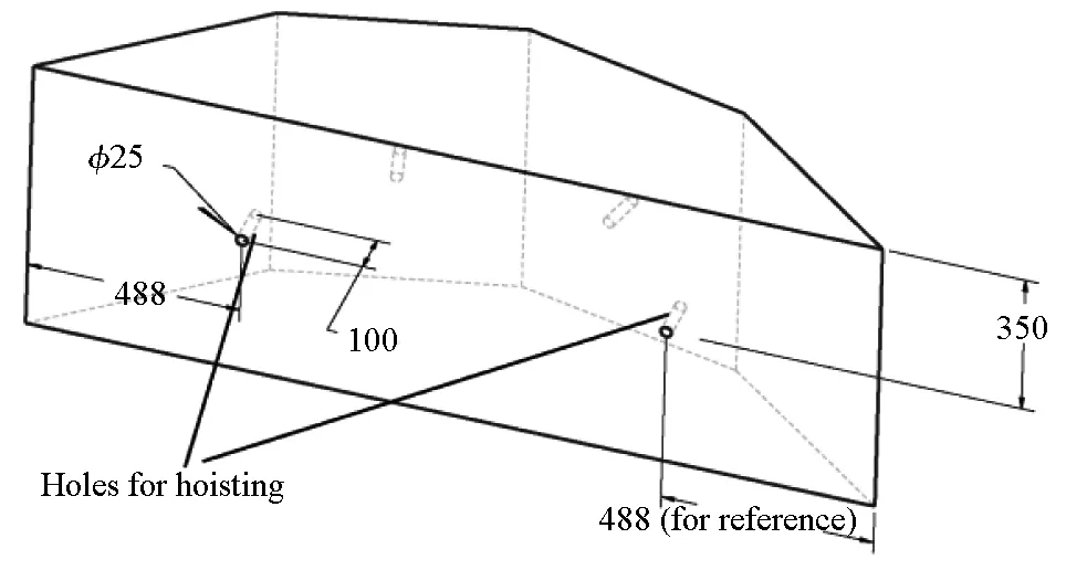
(a)
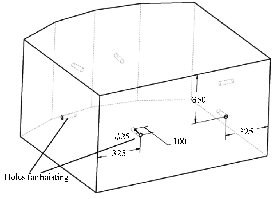
(b)Fig. 3 Forms of rock samples (unit: mm)
3.1.1.2 Experimental phenomena and result analysis
(1)Analysis on effect of rock breaking by disc cutter under different cutter edge spacings
The actual effect of rock breaking by disc cutter under different cutter edge spacings is shown in Fig. 4.
(a) Cutter edge spacing of 80 mm (b) Cutter edge spacing of 90 mm
(c) Cutter edge spacing of 100 mm (d) Cutter edge spacing of 110 mm
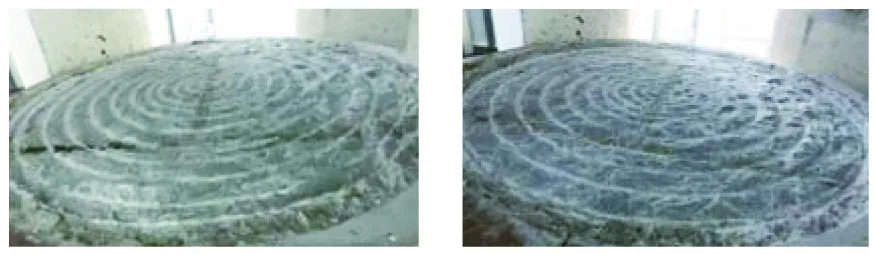
(e) Cutter edge spacing of 120 mm (f) Cutter edge spacing of 130 mm
Fig. 4 Effect of rock breaking by disc cutter under different cutter edge spacings
From Fig. 4, it can be seen that when the cutter edge spacing is 80 mm, 90 mm, 100 mm or 110 mm, the rock can be effectively broken, and there is no phacolith on the surface of rock sample; when the cutter edge spacing is 120 mm or 130 mm, unfallen rock locally exists within the cutter edge spacing on the surface of rock sample, but as the tunneling continues and the depth of penetration increases, such remaining rock can also fall.
The muck produced in experimental groups with different cutter edge spacings was screened and classified, with the results shown in Fig. 5.
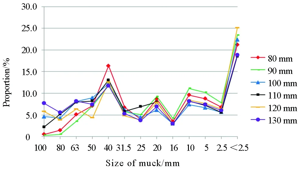
Fig. 5 Screen results of muck produced under different cutter edge spacings
According to Fig. 5, under different cutter edge spacings, the proportion of each muck size is slightly different, but the overall distribution is similar. The proportion of rock blocks with a size of 40-50 mm and that of rock powder with a size of less than 2.5 mm account for 11%-16% and 18%-25% respectively.
(2)Analysis on specific energy of rock breaking under different cutter edge spacings
By keeping the tunneling speed and the rotating speed of cutterhead steady, the specific energy of rock breaking under different cutter edge spacings was analyzed, with the relationship between the disc cutter edge spacing, penetration and the specific energy shown in Fig. 6.
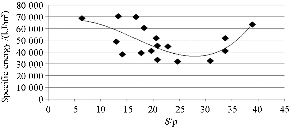
Fig. 6 Statistical relationship between S/p and specific energy
According to Fig. 6, for the granite, when the ratio of the cutter edge spacing to the penetration (S/p) is 25-30, the specific energy is the lowest (about 35 000-40 000 kJ/m3); when the cutter edge spacing is 80 mm, the best penetration is 2.7-3.2 mm/r; when the cutter edge spacing is 120 mm, the best penetration is 4-4.8 mm/r. From the viewpoint of specific energy only, the cutter edge spacing of 120 mm is relatively reasonable; however, the TBM tunneling of the project will encounter high-strength rock, and the actual average penetration of TBM is small. Therefore, 80 mm is adopted as the edge spacing of the front disc cutter spacing of the cutterhead, which is beneficial to the rock breaking by disc cutter; the cutter edge spacing of 90 mm or 100 mm is adopted for central disc cutter because of the small rock-breaking amount.
3.1.2 Research on adaptability of disc cutter wearing
The wearing of TBM cutters is influenced by the geological, mechanical and other factors. In order to understand the law of influence of such factors on disc cutter wearing, indoor wearing tests with the help of scaled disc cutter (small disc cutter) were performed (because the indoor cutter wearing amount of prototype disc cutter is relatively small, so it is difficult to obtain relevant data). The experimental apparatus is shown in Fig. 7.
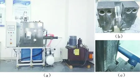
Fig. 7 Device for scaled disc cutter wearing test
3.1.2.1 Scaled disc cutter wearing test under different lithology
In order to explore the law of influence of rock abrasiveness on disc cutter wearing, scaled disc cutter wearing tests and rock abrasiveness tests were carried out for 5 kinds of rocks, i.e. granite, sandstone, diorite, limestone and marble.
(1)Scheme of scaled disc cutter wearing test under different lithology
The flat-edge disc cutter with a diameter of 1.7 inches and an edge width of 1.9 mm was adopted as the small disc cutter. The penetration speed of disc cutter was set to 0.05 mm/stroke; the stroke per attempt of cutting was 250 mm; after every 100 m was rolled by the disc cutter, the mass loss was weighed once, and the average value of the results of 3 times of weighing was calculated. The rock abrasiveness servo system was used to test the CAI of 5 kinds of rocks.
(2)Analysis on experiment results
The results of scaled disc cutter wearing tests and rock abrasiveness tests for 5 kinds of rock samples are as shown in Table 5.
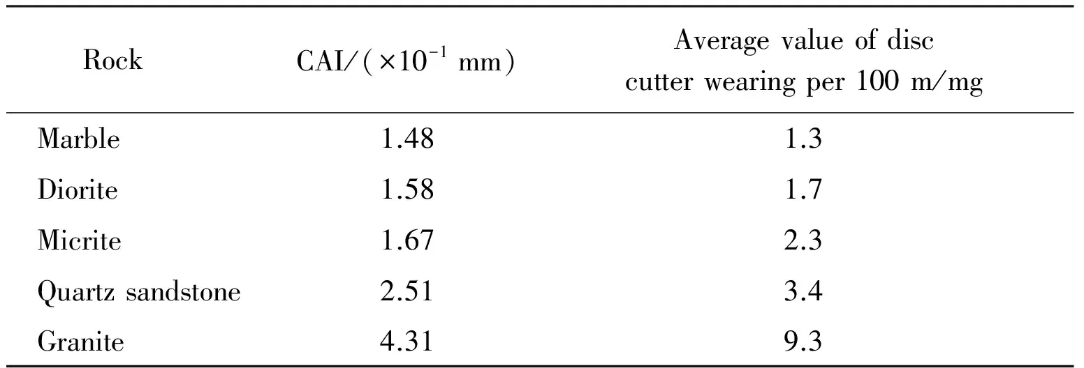
Table 5 Statistics of disc cutter wearing and CAI
By fitting the relationship between disc cutter wearing and CAI, the relationship between small disc cutter wearing per 100 m and CAI is:w= 0.784 5×CAI2, as shown in Fig. 8.
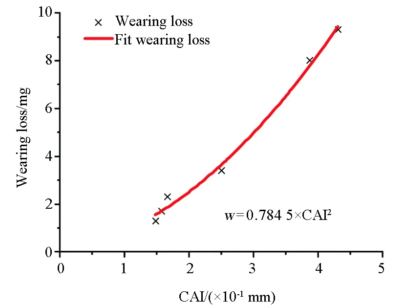
Fig. 8 Relationship between disc cutter wearing and CAI
From Fig. 8, the rate of disc cutter wearing is not only related to the compressive strength of rock, but also has a certain positive correlation with the rock abrasiveness indicator (CAI). In addition, although the compressive strength of diorite, limestone and marble was relatively high, it was observed during the experiment that the rock breaking efficiency of disc cutter was high, and the rock chips all dropped in large pieces, that is to say, the rock was brittle and the disc cutter wearing was relatively small.
3.1.2.2 Scaled disc cutter wearing test under different penetrations
(1)Scheme of scaled disc cutter wearing test under different penetrations
The flat-edge disc cutter with a diameter of 1.7 inches and an edge width of 1.7 mm was adopted as the small disc cutter. The penetration speed of disc cutter was set to 0.08 mm/stroke, 0.07 mm/stroke, 0.05 mm/stroke and 0.03 mm/stroke respectively; the stroke per attempt of cutting was 250 mm; after every 100 m (namely, 400 strokes) was rolled by the disc cutter, the mass loss was weighed once, and the average value of the results of 3 times of weighing was calculated. Such tests were carried out for gray granite (72 MPa, CAI of 3.5) and red granite (98 MPa, CAI of 3.8).
(2)Analysis on experiment results
Under 4 different penetration rates, the wearing loss per 100 m for gray granite and that for red granite are shown in Table 6.
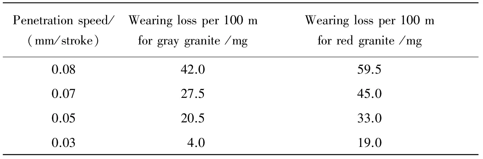
Table 6 Disc cutter wearings under different penetrations
The relationships between disc cutter wearing per 100 m and penetration of the two kinds of granite are shown in Fig. 9.
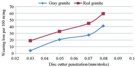
Fig. 9 Relationships between disc cutter wearing and penetration
From the above analysis, we can see that the abrasiveness of the selected red granite is significantly higher than that of the selected gray granite; with the increase of penetration, the wearing-induced mass loss of the disc cutter increases linearly. When the penetration reaches a certain value, the wearing-induced mass loss of the disc cutter increases sharply, mainly due to the large vertical force acting on the disc cutter under large penetration and thus the crimping of disc cutter edge caused. The edge material after crimping is more likely to fall off, which results in the sharp increase of the wearing-induced mass loss of the disc cutter. Therefore, it is recommended that during field TBM tunneling, the thrust should be controlled in such a way that no crimping of disc cutter edge occurs, which will help to control the disc cutter wearing.
3.1.2.3 Scaled disc cutter wearing test under different disc cutter types
(1)Different edge widths
The 1.9-inch disc cutters with edge widths of 1.9 mm, 1.6 mm, and 1.3 mm respectively were used, to carry out the disc cutter wearing tests under the condition that other experimental parameters are the same. The size of disc cutter for tests was reduced by 1∶10, with the material and process being the same as those of prototype disc cutter; the wearing-induced mass loss of small disc cutter was weighed via a balance (with a precision of 0.001 g). The experiment results are shown in Table 7.
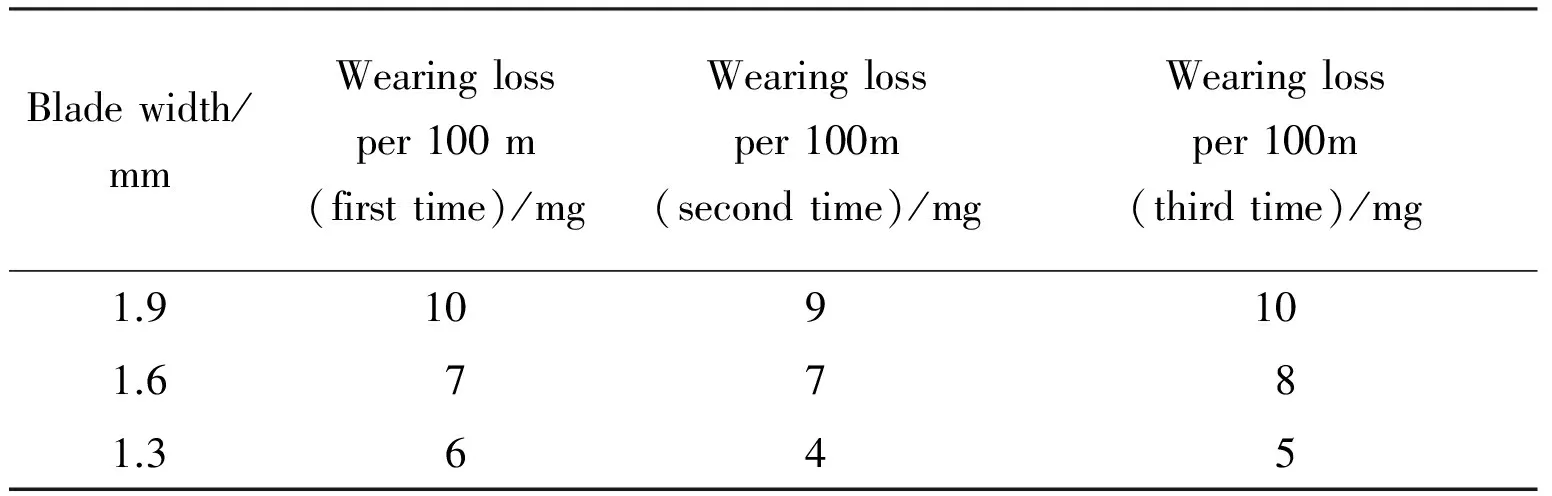
Table 7 Disc cutter wearings with different edge widths
According to the above result analysis, it can be known that the wearing-induced mass loss of disc cutters with different edge widths is basically proportional to the edge width, and thus it can be inferred that the radial wearing of disc cutter is seldom related to the edge width; from the viewpoint of experimental load, the load on the disc cutter does not decrease significantly even if the edge becomes narrow (the wearing-induced mass loss is proportional to the wearing-induced volume loss, and the wearing-induced volume loss is the product of edge width, perimeter and radial wearing; the wearing-induced mass loss is basically proportional to the edge width, and thus it can be inferred that the radial wearing is basically the same); from the viewpoint of the breaking of the rock sample, the penetration ability increases after the edge becomes narrow, but the cutting-through ability between two indentations weakens.
(2)Different disc cutter diameters
Small disc cutters with a diameter of 1.7 inches, 1.9 inches and 2.0 inches respectively were used in the tests, with the material and process being the same as those of prototype disc cutter. The disc cutter wearing tests were performed at a penetration speed of 0.05 mm/stroke. The experiment results are shown in Table 8.
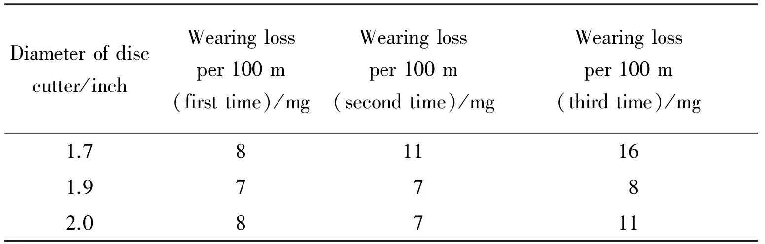
Table 8 Disc cutter wearings with different disc cutter diameters
From the analysis on the data in Table 8, it can be seen that when the diameter of the small disc cutter is changed, the wearing per 100 m of the disc cutter does not change significantly; hence it can be seen that there is no direct relationship between the wearing rate of the disc cutter and the diameter of the disc cutter. Meanwhile, the wearing per 100 m of the 1.7-inch-disc cutter increases step by step are mainly due to the significant crimping of the edge during the experiment. Therefore, large-diameter disc cutters are recommended as much as possible in the case of high-strength hard rock, and the service time of disc cutters can be extended by increasing the allowable wearing of the disc cutter.
(3)Different edge shapes
The rounded-edge disc cutter (1 mm in fillet) and flat-edge disc cutter with a diameter of 1.9 inches and an edge width of 1.9 mm were used for disc cutter wearing tests. The experiment results are shown in Table 9.

Table 9 Disc cutter wearings with different edge shapes
From the above experimental phenomenon, crimping appears on the worn-out flat-edge disc cutter, while no crimping appears on the worn-out rounded-edge disc cutter. From the viewpoint of wearing-induced mass loss, the wearing loss per 100 m of the rounded edge is significantly lower than that of the flat edge. Therefore, rounded-edge disc cutters are recommended in the case of high-strength hard rock.
3.2 Key parameters of TBM
The calculated value of each parameter of the TBM for Gaoligongshan Tunnel was obtained according to the known design parameters of the TBM and the calculation method for key parameters of open TBMs; the design value of each parameter of the TBM for Gaoligongshan Tunnel was determined according to the calculated value and some special requirements, as shown in Table 10.
The key design parameters of the TBM are as shown in Table 11.
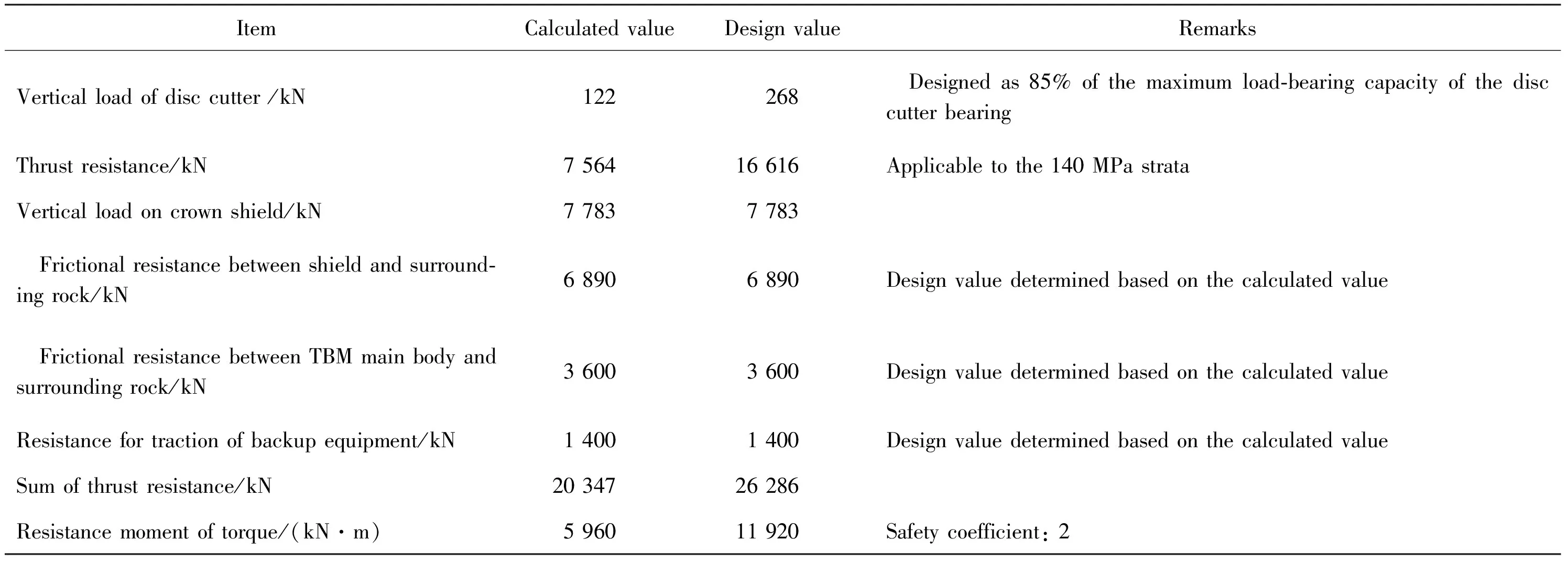
Table 10 Calculation parameters and design value for TBM of Gaoligongshan Tunnel
Table 11 Main design parameters of TBM of Gaoligongshan Tunnel
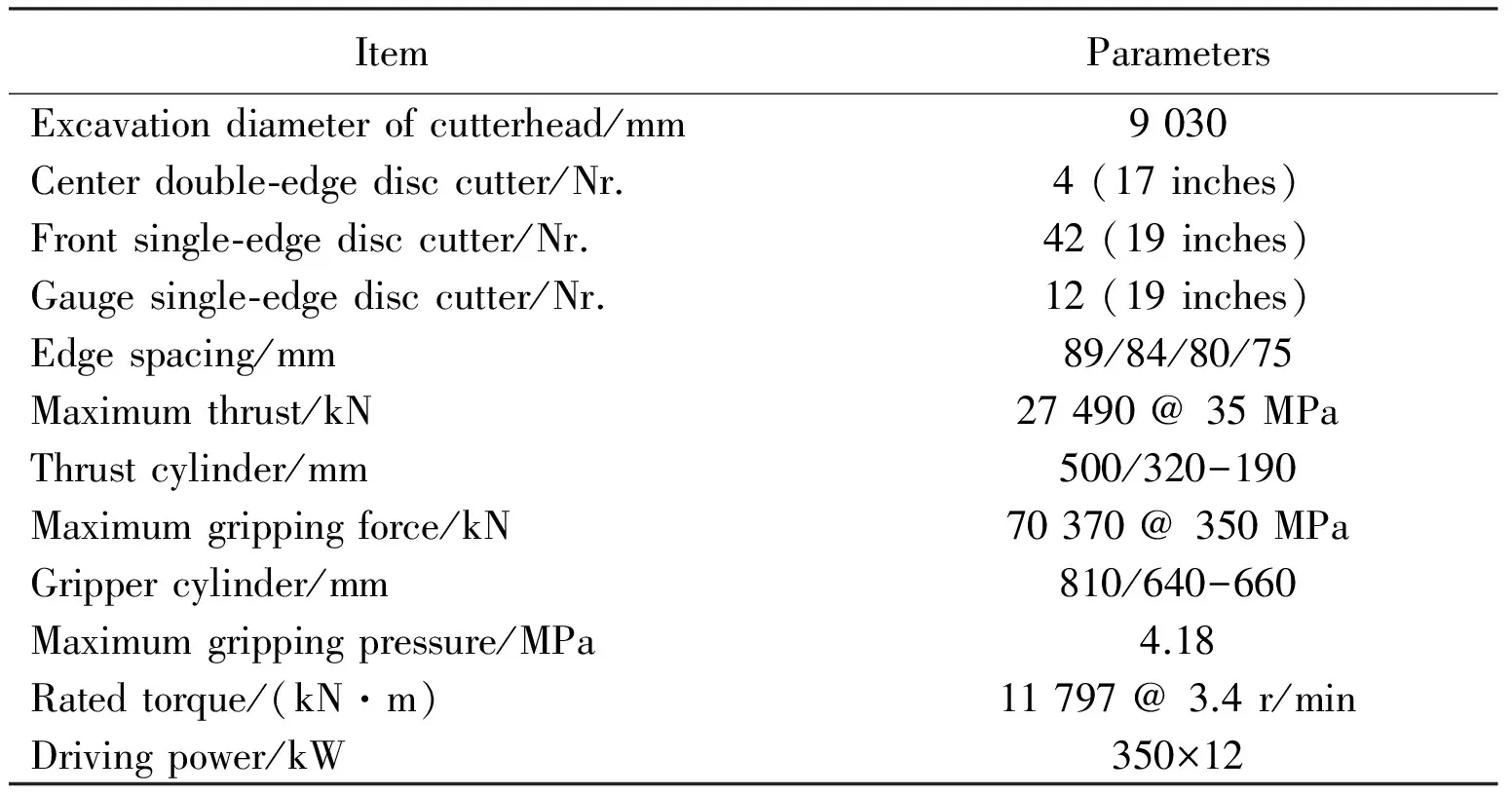
Item ParametersExcavationdiameterofcutterhead/mm9030Centerdouble⁃edgedisccutter/Nr.4(17inches)Frontsingle⁃edgedisccutter/Nr.42(19inches)Gaugesingle⁃edgedisccutter/Nr.12(19inches)Edgespacing/mm89/84/80/75Maximumthrust/kN27490@35MPaThrustcylinder/mm500/320-190Maximumgrippingforce/kN70370@350MPaGrippercylinder/mm810/640-660Maximumgrippingpressure/MPa4.18Ratedtorque/(kN·m)11797@3.4r/minDrivingpower/kW350×12
4 Research on design scheme of TBM
4.1 Design of efficient rock breaking of cutterhead and cutters
Due to the properties of rocks such as medium strength, good integrity and high quartz content, it is necessary to strengthen the rock breaking and protection measures for the cutterhead. The design concept is: completing the excavation and tunneling of the project without large-scale cutterhead repairing. According to the project overview and geological data, the overall design scheme of the cutterhead is: excavation diameter of 9.03 m, cutterhead material of Q345D, total weight of cutterhead of about 200 t, and cutterhead consisting of 5 blocks, as shown in Fig. 10.
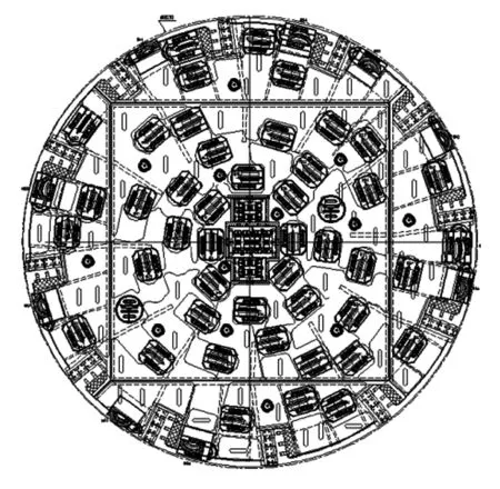
Fig. 10 Design pregram of cutterhead
4.1.1 Design of high strength of cutterhead
The center block and outer blocks of the cutterhead are made of forged plates with 270 mm thickness so as to reduce welds, increase the rigidity and strength of the cutterhead and improve the fatigue life of the cutterhead. The flange is made of forgings 300 mm thick, with high strength and good rigidity, to ensure the uniform stress and service life of the main bearing. The cutter saddle is made of the Q345D forgings, and is provided with irregular supporting plates on its back to increase the rigidity and strength of the cutter saddle and to ensure a long service life.
4.1.2 Small disc cutter spacing
The cutterhead is provided with 62 disc cutters in total. The edge spacing of the center cutters is 89 mm and that of the front cutters is 80 mm. As a result, a high rock breaking capacity can be achieved, the cutterhead vibration can be effectively reduced, and the service life of the cutters can be improved.
4.1.3 Nonlinear layout of cutters
The nonlinear layout of the cutters is helpful to ensure the uniform stress of the cutterhead, avoid large concentrated stress and extend service life of the cutterhead. Under the condition of the same rock strength, the nonlinear layout of the cutters can achieve small vibration and reduce the wearing of the cutters.
4.1.4 Multiple muck inlets of cutterhead
The cutterhead is provided with 12 muck inlets to provide enough space for mucks, ensure the thorough scraping of mucks and reduce the secondary wearing of the cutters. The scraper and the scraper holder are connected with high-strength bolts (back-mounted) to facilitate removal and replacement. Various muck guide plates are provided for muck inlets to improve the scraping efficiency and reduce the scraper wearing.
4.2 Over-excavation design of TBM
4.2.1 Diameter expansion of cutterhead
The TBM has two kinds of diameter expansions (i.e. 50 mm and 100 mm). The specific analysis is as follows: (1) In the case of 50 mm diameter expansion, gauge cutters #57-#62, CW1 and CW2 under the L-shaped block are provided with additional gaskets to increase their height (Fig. 11). (2) In the case of 100 mm expansion in the radial direction of the cutterhead, gauge cutters #56-#62, CW1 and CW2 shall be adjusted, while the other cutters are not adjusted. (3) The cutters #56, #57 and #58 shall be provided with additional gaskets to increase their height, and they shall be reassembled after the L-shaped blocks are removed for cleaning of surfaces of cutter saddles and L-shaped pieces. (4) For cutters #59, #60, #61, #62, CW1 and CW2, L-shaped block shall be replaced to increase their height. (5) The 20-inch cutters indicated in Fig. 11 are those composed of 19-inch cutter bodies and 20-inch cutter rings; however, CW2 is the 20-inch cutter with 40 mm eccentricity.
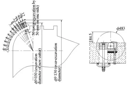
(a) Over-excavation sketch (b) Cushion on bottom of L-shaped block
Fig. 11 Design scheme of over-excavation by 50 mm on one side (unit: mm)
4.2.2 Drive lifting
In order to realize continuous long-distance over-excavation of TBM, in addition to the changing of the cutterhead diameter, the drive of the TBM shall be lifted so as to prevent gaps between the bottom shield and the surrounding rocks resulted from the enlarging of the cutterhead diameter. The bottom shield of the TBM is rigidly connected to the headstock with bolts. If over-excavation is needed, the connection bolts between the bottom shield and the headstock shall be removed after local over-excavation; and then, lifting cylinders shall be used to lift the headstock to a certain extent, so as to install steel plates with the corresponding thickness between the headstock and the bottom shield; finally, the headstock shall be rigidly connected to the bottom shield again.
4.3 Design of hidden advance drill
The structure of the advance drill is shown in Fig. 12. The advance drill, thrust beam and ring gear beam were designed separately in the lower part of the main beam platform. The advance drill shares the same pump station with the anchor drill system in Zone L1.
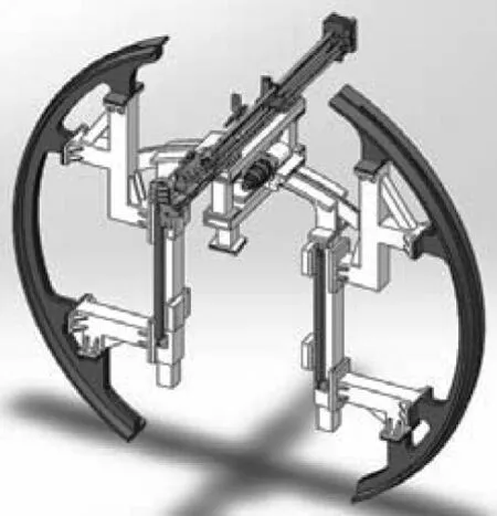
Fig. 12 Design program diagram of hidden advanced drill
In terms of normal tunneling, the advance drill is hidden in the lower part of the main beam platform along with one section of ring gear beam and two sections of ring gear beams fixed on both sides. If advance drilling is needed, the cylinders on both sides shall be used to lift the advance drill and the ring gear beam simultaneously to make the ring gear beam be connected with the gear beams on both sides so that an entire gear ring can be formed. The advance drill can travel around the gear beam at a certain external angle for drilling holes for advance anchor bolts, advance small pipes and advance pipe roofs and facilitating advance grouting equipment for advance support of surrounding rocks ahead of the cutterhead.
4.4 Design of integrated supporting system
The TBM is provided with the rebar panel supporting system, wiremesh storage system, steel arch assembling machine, anchor drill, emergency shotcreting system in Zone L1 and shotcreting system in Zone L2, and the rebar panel supporting range is expanded to 250°. The design scheme of the integrated supporting system is shown in Fig. 13.
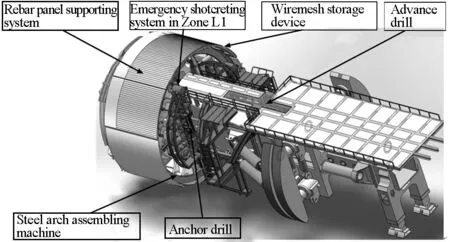
Fig. 13 Design scheme of integrated supporting system
In case of TMB passing through ground with unfavorable geological conditions, in order to reduce collapse and convergence after the surrounding rocks being exposed out of the shield, wet shotcreting manipulators shall be arranged in the main body section of the TBM to seal the surrounding rocks timely. Through the optimization of the structure and space of the TBM, arc tracks and racks shall be added to the steel arch gripping mechanism. In terms of the design of the rack, the track being contaminated and covered by rebound materials of shotcrete shall be taken into account to prevent the trolley being blocked and to protect the track. The gear is meshed with the rack to make the wet shotcreting trolley travel along the arc track. The nozzle for wet shotcreting is mounted on the wet shotcreting trolley and the distance between the wall of the tunnel and the nozzle can be adjusted.
In terms of feeding of wet shotcreting in Zone L1, the relay mode is adopted for concrete pumping. The wet shotcrete is conveyed to the two concrete pumps on the right of the equipment bridge via the shotcreting pump in Zone L2, and then is pumped to the nozzle for wet shotcreting in Zone L1 via those concrete pumps on the right of the equipment bridge.
4.5 Design of cooling system
Forced cooling system is installed on the TBM to reduce the temperature in the working area. Ice transported to the working area from outside the tunnel may also be used for cooling. In the design of the TBM cooling system, the heat generated by TBM equipment, rock walls and mucks shall be taken into account. The ventilation and cooling units will take away most of the heat. The calculation and analysis for type selection of key components of the cooling system are as follows.
(1)Analysis on type selection of cooling units
Model: cooling unit RTHE200, three units are installed in total, and space for installation of one unit is reserved;
Cooling capacity: 3 × 715 kW=2 145 kW;
Input power: 3 × 149.2 kW=447.6 kW;
Inlet water temperature: 25 °C;
Outlet water temperature: 35 °C;
Total inlet flow: 3×73.84 m3/h =221.52 m3/h.
(2)Type selection and calculation of air coolers
Elevation of air inlet entrance of tunnel: 1 250 m;
Air density: 0.99 kg/m3;
Air cooler power (when reducing the working area temperature to 28 °C): 3×714.8 kW=2 144.4 kW.
5 Research on advance geological prediction technology of TBM
5.1 Advance geological prediction technology with HSP method
5.1.1 Concept of advance geological prediction technology with HSP method
Based on the comparative analysis on the geological prediction results and field tests as well as previous research, the geological adaptability of TBM and shields and the development and technical parameters of supporting data acquisition equipment for advance geological prediction were researched. The development of advance geological prediction equipment with HSP method was carried out according to the characteristics of TBM to achieve a small geological prediction equipment, which can be integrated with TBM to perform the geological prediction. The advantages of the geological prediction technology are as follows: (1) The "passive source" is used as the excitation source, so that the drilling, blasting or hammering is not required. (2) Shutdown or extra cooperation from the construction team is not required so that the geological prediction has no impact on the construction. (3) The field test lasts for a short period (about 20 min) and the operation is convenient. (4) The prediction results are displayed in the form of 2D slices or 3D diagrams, and the results are intuitive and vivid.
5.1.2 Development of advance geological prediction system with HSP method
The dimensions of HSP NC system is 250 mm×250 mm×73.5 mm. The system is placed in the reserved space of the TBM for advance geological prediction. The receiver detector is installed based on the fast adhesion layout. The wireless transmission module includes a receiving module and a transmitting module. The receiving module is placed on the top of the main control cabin for receiving wireless data and transmitting them to the HSP NC system. The transmitting module is connected with the detector to receive the vibration signal and transmit the signal wirelessly. Real-time prediction data processing software was developed based on the HSP method. Real-time data acquisition and device parameter setting interfaces are shown in Fig. 14.
5.2 Advance prediction technology with RTP method
5.2.1 Prediction principle and instrument system
The ground temperature field consists of the temperature-variable zone, temperature-constant zone and temperature-increasing zone. Most tunnels are constructed in temperature-increasing zones. According to the gradient theory of the ground temperature, the temperature field in the temperature-increasing zones can be obtained via calculation. Subject to the dynamic change, the groundwater continuously exchanges heat with the rock mass, and thus, the distribution of the temperature field will be changed, resulting in distortion. In terms of the RTP method, scientific prediction is achieved through predicting the condition of the groundwater during the construction of the tunnel based on the distortion principle of the temperature field within the excavation range of the tunnel as well as the location and range of the temperature field distortion, so as to prevent groundwater disasters during the construction of the tunnel (Fig. 15).
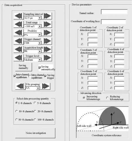
Fig. 14 Interface for data acquisition and device parameters
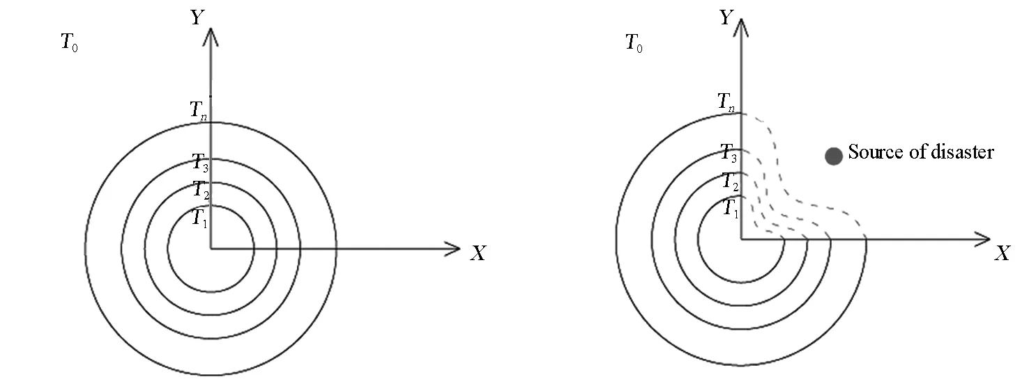
(a) Theoretical temperature field (b) Distorted temperature fieldFig. 15 Prediction principle of RTP method
The independently-developed geological prediction apparatus with RTP MSASW instrument was adopted, and dedicated portable sensor installing system is equipped. This instrument is provided with the internal power supply to power the sensors.
5.2.2 Field data acquisition and data processing & analysis
Before test, a suitable location in the tunnel was selected to conduct the best drilling test to obtain the depth data of the surrounding rocks of the stable temperature field. In the surrounding areas behind the excavation face of the tunnel (left sidewall, crown and right sidewall), a row of boreholes with fixed depth was uniformly drilled along the tunnel axis according to certain rules, and sensors were placed at the bottom of the borehole before the boreholes were filled with mortar and sealed (Fig. 16). After 12 hours of stabilization, the sensor data was obtained with a thermometric instrument.
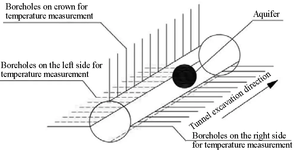
Fig. 16 System layout on site
The data processing system mainly includes:
(1)Data preprocessing: input the corresponding parameters (coordinates, kilometerage and elevation) for each measurement point.
(2)Terrain correction: the result of rock mass temperature test is influenced by the terrain and it is difficult to evaluate the result. Through the terrain correction, the influence of the groundwater on the temperature field of rock mass can be highlighted.
(3)Gridding and regression analysis: the finite element calculation of the profile formed by the entire survey line can be conducted through gridding, so that the temperature field of rock mass in the whole region can be obtained. The regression analysis aims to establish a functional relationship for the survey line. The resulted characteristic curve can be used to calculate the groundwater location ahead of the working face of the tunnel.
(4)Automatic mapping and output: the output of results mainly includes the characteristic curve of the temperature field of rock mass and the 2D contour map of the temperature field of rock mass.
6 Conclusions and suggestions
Prototype disc cutter rock breaking experiment and scaled disc cutter wearing experiment were carried out based on the complex geological conditions of Gaoligongshan Tunnel on Dali-Ruili Railway such as high ground temperature, high ground stress and high seismic intensity, as well as active neotectonic movement, active geothermal water environment, active externally-driven geological conditions and active bank slope surface reconstruction, and the design scheme of the TBM with highly adaptability to the project was proposed. Based on the research, breakthroughs have been made in key technology fields such as excavation by TBM in weak sections with large deformation and coping with environment with high ground temperature, and the TBM which can be adapted to the complex geological conditions was developed and applied to Gaoligongshan Tunnel on Dali-Ruili Railway. In order to improve the adaptability of the TBM to different geological conditions, related research will be further carried out in later stages in the following aspects according to the construction conditions of Gaoligongshan Tunnel:
(1)Research on adaptability of key TBM parameters to different grounds: based on the principle of rock-machine interaction, the key elements of adaptability design for the TBM cutterhead and thrust system will be researched. In the aspect of cutterhead design, the theory and method for adaptability design of TBM rock breaking will be established. Based on the geological and hydrological conditions of the project, the key TBM parameters will be calculated with the help of the rock-machine interaction model.
(2)Research on key technologies for excavation of weak and variable cross-section tunnels with large deformation by TBM: for the long-distance weak surrounding rocks of the project, in order to prevent the tunnel convergence caused by the large deformation of weak surrounding rocks, the requirements of long-distance over-expansion and tunneling shall be taken into account in the process of determining the excavation diameter of the TBM, and the excavation and support structures shall be innovated. Numerical simulation will be conducted based on the motion theory, strength theory and rigidity theory of the mechanisms for mechanical design to analyze the action, rigidity and strength of key mechanisms such as cutterheads and shields and to obtain the mechanism and structure forms applicable to key components for full-face excavation of tunnels with variable cross-sections, so as to guide the design of key components and systems for variable cross-section excavation and supporting by TBM.
(3)Research on key technologies for prevention and control of high ground stress and rockburst: due to the high ground stress, frequent rockbursts occur to the ground. The project is located in the ground with high cover and high ground stress and the risks of rockburst are extremely high. Rockburst prediction methods will be studied based on comparison of advantages and disadvantages of microseismic movement and acoustic emission. In addition, methods and measures for prevention and control of rockbursts will be proposed through the space-time analysis on high ground stress and rockburst.
(4)Research on key technologies for adaptability of fast tunneling by TBM in fractured ground: in view of the problems such as low TBM tunneling efficiency and large construction risks in weak and fractured ground, as well as TBM jamming (cutterheads and shields being jammed) and collapse, based on the stability characteristics of rocks and disturbance, the numerical analysis method will be adopted to analyze the space-time evolution of rock properties and to propose measures against jamming of TBM shields and methods for fast supporting, so as to provide theoretical support for the design of TBM shields and fast supporting devices.
(5)Research on key technologies for TBM tunneling environment protection in ground with high ground temperature: high ground temperature may be encountered in the TBM tunneling section; according to the design data of the project, with the ground temperature redundancy taken into account, theoretical analysis on the equipment heat exchange and the tunnel ventilation will be carried out in respect of such aspects as equipment operating temperature and ambient temperature of the working area, so as to provide prevention and control measures and theoretical basis for TBM tunneling environment protection systems in ground with high ground temperature.
(6)Research on key technologies for preventing water inrush during tunnel construction by TBM: according to the construction characteristics of the tunnel with deep overburden, the complex engineering geological conditions and hydrogeological conditions of the project shall be analyzed. Water-rich sections shall be selected to analyze the maximum amount of water inrush by the seepage field analysis method. Based on the water inrush pressure and the flow characteristics, the feasibility of measures for advance grouting to improve the geological conditions and seal the water will be analyzed to propose technology measures for advance grouting and to guide the adaptability design of TBM in water inrush ground, as well as to guide the type selection and design of TBM drainage devices according to the principle of limit point for water inrush and to put forward requirements on the waterproof design of the mechanical, electrical and hydraulic devices.
Acknowledgement
The study was supported by Research and Development Plan Project of China Railway Corporation (2016G004-A).
[1]YANG Cihua. WT project report: Lesotho [J]. Tunnel Translation, 1994(3): 22.
[2] WU Zhiming. Imaging the Taiwan Strait Tunnel inspired by the Channel Tunnel[J]. Railway Knowledge, 2005(2): 42.
[3] XIAO Shu′an,SATTEL G. Geological advance prediction measurement in Swiss Vereina tunnel project [J]. Guangdong Highway Communications, 1998(S1): 115.
[4] WILLIS D. The development of TBM [J]. Translator: CHENG Fangquan. Express of Water Resources & Hydropower Information, 2013(11): 24.
[5] WANG Mengshu. Tunneling by TBM/shield in China: State-of-art, problems and proposals [J]. Tunnel Construction, 2014, 24(3): 179.
[6]ZHAI Lianghao,WU Jinghua. The application of TBM to introduction of the Songhua River water supply project in Jilin central cities [J]. Journal of Changchun Institute of Technology (Natural Science Edition), 2016, 17(1): 71.
[7] WU Shiyong, WANG Ge, XU Jinsong, et al. Research on TBM type-selection and key construction technology for Jinping Ⅱ Hydropower Station [J]. Chinese Journal of Rock Mechanics and Engineering, 2008, 27(10): 2000.
[8] SU Lijun. Theory and technology of stability control of surrounding rock of deep buried soft rock tunnel construction[D]. Wuhan: Wuhan University, 2010.
[9]CHEN Bingrui, FENG Xiating, ZENG Xionghui, et al. Real-time microseismic monitoring and its characteristic analysis during TBM tunneling in deep-buried tunnel [J]. Chinese Journal of Rock Mechanics and Engineering, 2011, 30(2): 275.
[10] SUN Zhenchuan, CHEN Jianli. Construction technologies for open TBM used in karst areas and soft-weak and broken grounds: Case study of Songhua River Water Diversion project [J]. Tunnel Construction, 2017, 37(2): 215.
[11] QIAN Qihu. Main developments and directions of geological prediction and informatized technology of tunnel construction [J]. Tunnel Construction, 2017, 37(3): 251.
[12] CHEN Bin, LIU Jishan. The application of TBM technique in contemporary rock tunnel engineering [C]// Proceedings of the Shanghai International Tunnel Engineering Symposium, 2005. Shanghai: Shanghai Society of Civil Engineering, 2005: 281.
[13] JU Qifeng, XIE Xinsheng. Georgia Kaduli hydroelectric project power tunnel construction scheme & construction organization optimization [J]. Design of Hydroelectric Power Station, 2004, 20(3): 30.
[14] HE Chuan. Challenges and prospectives of construction of long-distance inclined shafts of coal mines by shield/TBM [J]. Tunnel Construction, 2014, 34(4): 287.
[15] ZHAI Jinying. State-of-art and prospects of TBM tunnel construction[J]. Tunnel Construction, 2002, 22(4): 60.
[16] ZHU Hong, ZHU Xiaohong. Recent developments in hydropower development in several Asian countries [J]. Express of Water Resources & Hydropower Information, 2014, 35(9): 16.
[17] JING Liujie, ZHANG Na, YANG Chen. Development of TBM and its construction technologies in China [J]. Tunnel Construction, 2016, 36(3): 331.
[18] ZHOU Ruoyu, ZHOU Qing. Structure and assembly technology of the domestic first double shield TBM [J]. Construction Machinery, 2016(5): 61.
[19]CAO Cuichen, MENG Jinzhong, FAN Anshun, et al. Development of TBM in China and abroad and its application in YRDP [J]. Water Resources and Hydropower Engineering, 2001, 32(4): 27.
[20] YU Xinhong, CHEN Yongzhang, YAN Kai. Development and prospect of TBM tunneling technology [J]. Water Conservancy and Hydropower Project Cost, 2003(1): 45.
[21] XUE Beifang. Current state and development strategy of shield TBM in China [J]. World Tunnelling, 1999(6): 26.
[22] QIAN Qihu, LI Chaofu, FU Deming. Spreading the use of TBM, promoting development of underground space in China [J]. Construction Machinery, 2002(5): 28.
[23] YAN Jinxiu, WANG Jianyu, FAN Wentian. Technological development and current application of TBM [J]. World Tunnelling, 1998(4): 1.
[24]REYNOLDS P. Latest progress in construction of TBM tunnel of hydropower project [J]. Translators: MENG Zhaowei, MA Guisheng. Express of Water Resources & Hydropower Information, 2016, 37(4): 24.
[25]XIE Wenqing. Mechanism of rock-burst in underground works and countermeasures [J]. Modern Tunnelling Technology, 2008, 45(4): 8.
[26] LIU Shaobao, LI Cangsong, DING Jianfang, et al. Forecasting technologies of ground water with TBM construction [J]. Chinese Journal of Engineering Geophysics, 2009(S1): 117.
[27] CHEN Yuan. Research on key technology of TBM selection and construction [D]. Shijiazhuang: Shijiazhuang Tiedao University, 2015.
[28] CHEN Kui, YANG Yandong. Discussion on design of TBM with high adaptability to Gaoligongshan Tunnel [J]. Tunnel Construction, 2016, 36(12): 1523.
[29] DU Lijie. Progresses, challenges and countermeasures for TBM construction technology in China [J]. Tunnel Construction, 2017, 37(9): 1063.
[30]WANG Yusuo, YANG Chao, YE Yuezhong, et al. Experimental study of stress characteristics of lining structures of tunnels in high geo-temperature environment [J]. Tunnel Construction, 2013, 33(10): 809.