Two-dimensional analysis of progressive delamination in thin film electrodes
Mei Liu·Bo Lu·Dong-Li Shi·Jun-Qian Zhang
List of symbols
x(andη),z(andζ)Cartesian coordinates(m)
LandhLength and thickness of the active layer(m)
L cCritical size for delamination(m)
cMolar concentration of lithium-ions(mol·m−3)
cmaxStoichiometric saturation concentration(mol·m−3)
caveAverage concentration(mol·m−3)
ϕInhomogeneity of concentration(mol·m−1)
N xandQ xzNormal and shear force resultant(N·m−1)
MxBending moment of active layer(N)
McDiffusion-induced bending moment
(N)
i nSurface current density(A·m−2)
¯iElectrochemical load factor
DDiffusivity of lithium-ions(m2·s−1)
ΩPartial molar volume of active material(m3·mol−1)
p(andσn)Interfacial normal stress(N ·m−2)
q(andσt)Interfacial shear stress(N ·m−2)
σncandσtcInterfacial normal and shear strength(N·m−2)
σx,σz,τxzStresses(N ·m−2)
εx,εz,εxzStrains
δnandδtInterfacial opening and sliding dis
placement(m)
δncandδtcCritical opening and sliding displacement(m)
ΓInterfacial fracture toughness(J·m−2)
υpandυsPoisson’s ratio of active material and
substrate
EpandEsYoung’s modulus of active material and substrate(N·m−2)
upandwpDisplacements of the active layer(m)
u0Mid-plane displacement(m)
usandwsDisplacements of substrate surface(m)
L1andL2Rigid displacements of the active layer and substrate(m)
IBending stiffness of active layer(N·m)
GpShear modulus of the active layer(N·m−2)
μFriction coefficient
QState of charge(SOC)
tTime(s)
¯tcTime to delamination onset
FFaraday constant(s·A ·mol−1)
H1Sliding displacement related to the interfacial stresses
1 Introduction
The lithium-ion battery is one of the main power sources due to its high operation voltage,high energy density,low self discharge rate,and long cycle life[1].In order to satisfy the increasing requirements of energy density and power density,candidate materials have been investigated for the new generation of the electrodes.The capacity of a traditional carbonaceous anode is372 mAh/g[2],which is considerably lower than 4000 mAh/g for silicon[3].However,the volumetric change for the silicon electrode is much larger than the carbonaceous anode.Si experiences more than 300%volumetric change when it is fully lithiated[4,5].This may result in greatly high stresses and hereafter cracking or delamination of the electrodes[6].Consequently,the capacity loses and cycle performance fades during charging-discharging cycles[7].
There are many studies attempting to reduce the damage of the silicon electrodes and consequently improve the electrochemical performance.Some investigations mainly focus on altering structures of the electrodes,such as nanowires[8],particles[9,10],and thin films[11].Subsequently,patterned silicon islands are fabricated as active material[12],which may avoid the in-plane cracking[13].However,the delamination in the interface between active material and current collector still exists[6,12].
Several theoretical and experimental works addressed the delamination in thin film electrodes.For instance,Xiao et al.[12]found that a smaller size than a critical value can avoid the interfacial delamination.Meanwhile,Haftbaradaran et al.[14]used the shear-lag model to predict the critical size,in which the energy release rate is used as the delamination criteria in both two-dimensional and axisymmetric structure.Based on the cohesive model Pal et al.[15]focused on the impact of elastic-plastic deformation in the current collector on interfacial delamination.In addition,Liu[16]discussed the active layer debonded from a rigid substrate by using the finite element calculation with the cohesive model.Also,Prezas et al.[17]observed that the degree of delamination is proportional to the charge rate in constant-current cells.
In our previous work[18,19],the evolution of the interfacial delamination has been studied by employing the cohesive model under the axisymmetric condition.However, the actual structure of the silicon islands is not necessarily the circular disk.For instance,the patterned silicon islands fabricated by Xiao etal.[12]were square.To some extent,plane strain and plane stress are two extreme cases for the three-dimensional problem of the rectangular plate.The symmetrical cross section of the rectangular plate can be an analogy with the plane strain condition since the normal and shear strains on the cross section are zero.Likewise,the edge surface of the rectangular plate is in accord with the plane stress condition.The stress/strain conditions in the rest region of the rectangular plate are in some measure between plane strain and plane stress.Hence,the plane analysis will be employed to evaluate the delamination for the rectangular island electrode as two extreme cases.
The present work aims to develop a semi-analytical model with plane analysis for the interface delamination caused by diffusion-induced stresses.Several key factors of delamination will be obtained and evaluated.The impact of the constraint perpendicular to the plane will be discussed by comparing the two presented plane conditions.Finally,a formula for the critical size will be provided.
2 Concentration profile
Consider an electrode consists of an active layer and a substrate,as shown in Fig.1.The strip with widthhand length 2Lrepresents the active layer bonded to the semi-infinite substrate,which represents the supporting structures.The Li-ions transport through both top and edge surfaces,and diffuse along the directions of thickness and length during charging or discharging.
In the present work,the charging/discharging behaviors of thin film electrodes are investigated under galvanostatic conditions.It is assumed that the diffusion is governed by Fick’s second law

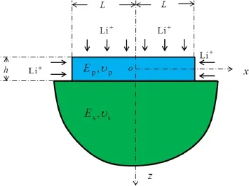
Fig.1 A strip active layer bonded to a semi-infinite substrate
wherecis the molar concentration of Li-ion in the active layer andDis the diffusivity.The initial molar concentration is assumed to be zero

Neglecting the electrochemical kinetics at the free surfaces during insertion and extraction,we assume the current density is uniform over the top and edge surfaces of the active layer and is proportional to cell current.Finally,the boundary conditions can be described as[19]
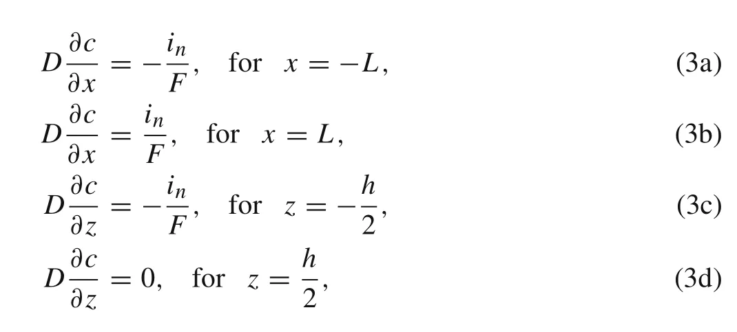
whereF=96485.3 C/mol is Faraday constant,inis the surface current density for which magnitude is fixed during galvanostatic operation[20].The sign ofinis positive for lithiation while negative for delithiation.Consequently,by using the method of separation of variables,the dimensionless concentration in the active layer can be obtained as follows[21]
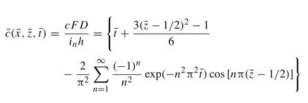
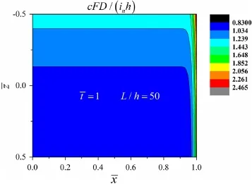
Fig.2 Distribution of dimensionless concentration
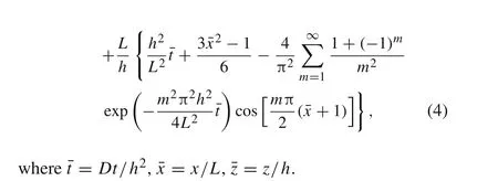
Figure 2 illustrates the distribution of Li-ions,taking into account the edge diffusion.The figure only shows the region of¯x>0,because the structure is symmetric about thez-axis.
3 Two-dimensional analysis for delamination
The damage would start from the edge while deformations of the active layer and substrate mismatch.There are three zones during the delamination in the interface,i.e.,damage free zone,cohesive zone,and debonding zone[19],as shown in Fig.3.The stresses and the corresponding displacements are considered to be continuous in the damage free zone,since the interface is bonded perfectly.The triangular cohesive law is employed in the cohesive zone,the region ahead of the propagating crack.The triangular cohesive[22]is used to explain the constitutive behavior of the interface,and can be described as

whereδnandδtare the interfacial opening and sliding separations,respectively,whileδncandδtcare corresponding critical values.The delamination occurs when the opening or sliding separation is greater than its limit.σnandσtare the interfacial normal and shear stresses,respectively.σncdetails of the cohesive law for the plane stress and plane strain cases might be different[23],it is also believed that two most important properties of the cohesive model are the strength and the fracture energy[24].Therefore,in the present work,the same cohesive model for both cases is assumed.

There are normal stress and shear stress in the interface of the active layer and the substrate as shown in Fig.4.The active layer can be modeled as a strip in plane with the distributed vertical loadp(x)and horizontal loadq(x)provided by the substrate,and the interfacial normal and shear stresses are equal to the vertical and horizontal loads,respectively,i.e.,σz(x)=p(x),τxz(x)=q(x).The stresses can be solved by adopting plane analysis and exploiting the interfacial conditions described above.As for the substrate,it is regarded as an elastic problem of a semi-infinite plane.
For the active layer,the constitutive equation solving the plane stress problem can be written as

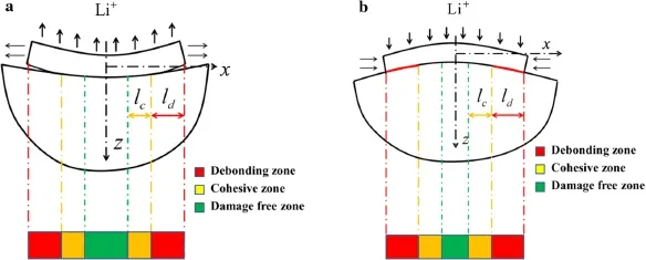
Fig.3 The deformation and the corresponding delamination caused by a lithiation and b delithiation
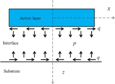
Fig.4 Interfacial stresses p(x)and q(x)caused by the charging


The nonzero stresses boundary conditions for the active layer are given as

The stresses can be expressed as functions of the displacements
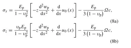

Substituting Eq.(8a)–(8c)into the balance equations,then integrating the obtained equations and combining with the boundary conditions,we have the differential functions as follows


The corresponding boundary conditions for Eq.(9a)and(9b)are

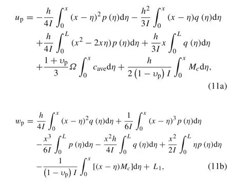
whereL1is an unknown constant that represents the rigid vertical displacement of the active layer.The interfacial displacements of the active layer can be resolved once the stressesp,q,and the concentrationcare determined.
The substrate endures the stresses in the region of the interface as the result of the interaction between the active layer and substrate.Thus,the boundary conditions can be described as

The displacements on the surface of the semi-infinite substrate read as[26]

whereusandwsrepresent the lateral and vertical displacements,respectively.The subscript s represents the substrate,e.g.,Young’s modulusEsand Poisson’s ratioυs.L2is the rigid vertical displacement.The interfacial displacements of the substrate can also be resolved once the stressespandqare determined.
In the damage-free zone,the horizontal and vertical interfacial displacements are continuous,i.e.,up=usandwp=ws,while stressespandqare also continuous in the interface.The interface falls into the cohesive zone when the stresses exceed the corresponding restrictions.In the cohesive zone,pandqare still continuous,but the interfacial displacements are no longer continuous and have the relationships ofup+δt=usandwp+δn=ws.The cohesive stresses are linear with the corresponding interfacial separations,when the plate and the substrate separate completely,that is in the debonding zone.For the opening crack in the debonding zone,there is no interfacial stress,i.e.,p=q=0.For the closing crack,the normal stresspand the deflections are continuous,i.e.,wp=ws,while the shear stress is induced by friction,i.e.,q(x)=sgn(δt)μp(x),whereμis the friction coefficient.


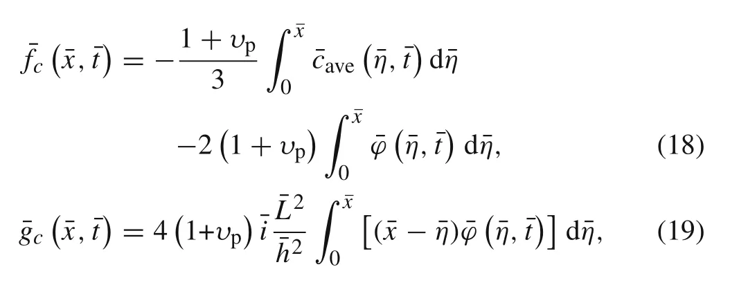
The integral governing equations with dimensionless interfacial stresses can be obtained as




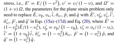
Due to the relation ships between the plane strain and plane
4 Results and discussion
4.1 Evolutions of delamination with charging time


Fig.5 Evolution of normalized length of debonding zone against the charging time compared in plane stress and plane strain for variations of a length of active layer¯L,b thickness of active layer¯h,c electrochemical load factor¯i,d Poisson’s ratio of active layer υp,e Young’s modulus ratio¯E,f cohesive strength¯σtc,and g Poisson’s ratio of the substrate υs

Figure 5a,b illustrates the impact of the sizes(¯Land¯h)of the active layer.Smaller length or thickness of the plate,leads to slower growth of delamination.Therefore,Fig.5a,b tells that the active layer should be prepared in small sizes to mitigate the interfacial damage of the electrode.It is also found that the difference between the plane strain and plane stress is significantly affected by the sizes of the active layer,which means the constraint perpendicular to the plane would play a great role on delamination in small size silicon island electrodes.
Figure 5c shows the effect of the charging operation.Smaller¯ileads to slower damage initiation and slower growth speed of delamination.An increase of¯iwould significantly reduce the difference between two plane conditions.Besides,it is found that¯ihas more influence on the plane stress than plane strain.Therefore,it is suggested that the smaller electrochemical load factor is preferred in the operation of batteries,especially for the plane stress condition.
Figure 5d demonstrates the evolution of the debonding zone for different Poisson’s ratio of the active layerυp.Interestingly,υphas considerable impact on the delamination process in plane strain.It might be caused by the effect of Poisson’s ratio,i.e.,the extra deformation along thex-axis induced by the constraint perpendicular to the plane.This also suggests that employing the active material with a smaller Poisson’s ratio is a possible strategy to delay the damage initiation.
In Fig.5e–g,it is found that the Young’s modulus ratio¯E,the dimensionless cohesive strength¯σtc,and the Poisson’s ratio of the substrateυshave insignificant impact on the delamination.Especially forυs,its variation barely impacts on the delamination process.As to¯Eand¯σtc,only the onset and the early stage of the delamination are slightly affected by them,which is consistent with the results of Lu etal.[27].
4.2 The time to delamination onset
In order to avoid the delamination,a possible strategy of partial charge,which controls the state of charge(SOC)or the charging time and terminates the charging process before damage occurs,has been presented in Ref.[27].Since the impact of partial charge on decrease of cell capacity is limited[27,28],accelerated fatigue caused by partial charge should not be a major problem compared with the dramatic volume change of the Si electrode.The critical SOC or time to delamination onset is the necessary parameter for the utilization of the partial charge method.In galvanostatic charge operation,the SOC is directly proportional to the dimensionless time.Hence,the time to delamination onset will be discussed via the seven parameters of¯i,¯σtc,¯E,υp,υs,¯h,and¯Lin this section.
Figure 6 illustrates the effect of the parameters on delamination initiation,where the plane strain is also compared with plane stress.It is also found that the delamination onset for plane strain is earlier than the one for plane stress.This phenomenon is consistent with the conclusion of Fig.5,indicating that plane constraint for plane strain condition accelerates the delamination.
Figure 6a,b plots the impacts of the sizes of active layer,which show that the time to delamination onset decreases with the increase of both dimensionless thickness¯h=h/δtcand dimensionless length¯L=L/δtc.Meanwhile,the difference between plane strain and plane stress is significantly affected by the sizes,especially in the range of small sizes.These results are consistent with the ones of Fig.5a,b.
Figure 6c shows the dimensionless critical time with respect to the dimensionless charging velocity.Small¯ican delay the delamination onset significantly.When¯ivaries from 2 to 20,the critical time for delamination initiation¯tcdecreases to approximately 10 percent of its original value,which may explain why rapid charging is not preferred in real operations.Besides,the difference between plane stress and plane strain is also considerably affected by¯i.
Figure 6d illustrates the impact of the Poisson’s ratio of the active layerυpon the delamination onset.The critical time reduces almost linearly with increase ofυp,indicating that the Poisson’s ratio of the active layer is another key factor that influences the delamination process.The significant increase of difference between the two curves also indicates that the difference between plane strain and plane stress is mainly caused by the effect of Poisson’s ratio of the active layer.
Figure 6e–g shows the influence of Young’s modulus ratio¯E,the dimensionless cohesive strength¯σtc,and the Poisson’s ratio of the substrateυs.It is found that large¯Eor small¯σtctend to induce delamination,although the impact is insignificant.Moreover,as shown in Fig.6g,the delamination onset has an invisible weak dependence on the Poisson’s ratio of the substrateυs.
Except¯iwhich represents the electrochemical load,the other six parameters all stand for the material properties and the geometry sizes.Comparing the six curves in Fig.6a,b,d–g,it is found that the influence of dimensionless length¯Lon the delamination initiation is the most significant.Thereby the delamination onset can be significantly delayed by using a smaller active plate.This tells us that a critical length seems to exist for the island electrodes in which delamination could not occur at all.
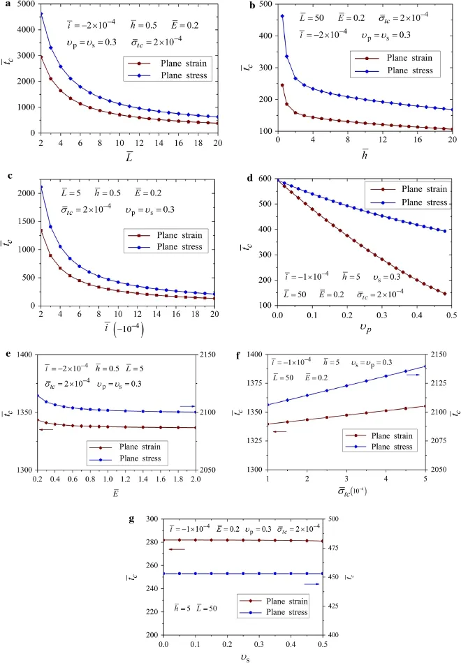
Fig.6 The time to delamination onset with respect to different parameters of the dimensionless.a Length of active layer¯L,b thickness of active layer¯h,c electrochemical load factor¯i,d Poisson’s ratio of the active layer υp,e Young’s modulus ratio¯E,f cohesive strength¯σtc,and g Poisson’s ratio of the substrate υs
4.3 The critical size for delamination
It has been reported that reducing the size of the thin film electrode smaller than a critical value is another possible strategy to avoid delamination[12,14,27].Therefore,this section will investigate the critical size and draw a comparison between plane strain and plane stress.It has been reported that the critical size for delamination caused by diffusion-induced stresses only exists when mode-II(sliding)is the dominated mode[27].Similarly,in the present work,the critical size will be only discussed when the dominated interfacial damage is sliding.
SOC can be obtained as follows[27]

while a lithium-ion cell is charging in galvanostatic operation,whereΩcmaxis the maximum volumetric strain,cmaxis the stoichiometric saturation concentration,andQis the SOC.
The sliding displacement happening at the edge,i.e.,¯x=1,can be described as
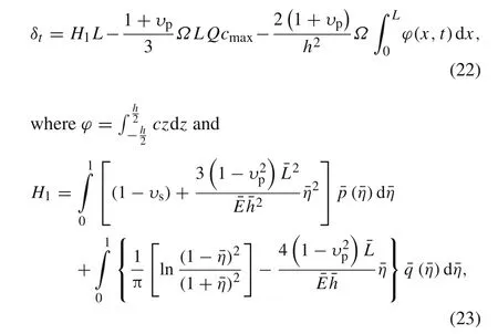
in which the interface stresses¯p,¯qcan be solved by the governing Eqs.(15a)–(17d)and Eq.(20).
The delamination begins when the sliding displacement reaches the limit,i.e.,δt=δtc.Substituting it into Eq.(22),the condition of the delamination initiation can be obtained as

Considering the critical case that delamination does not occur

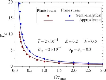
Fig.7 The dimensionless critical size against the maximum volumetric strain in both plane strain and plane stress,where the solid lines denote the approximate analytical expression and the points represent the semi-analytical solution
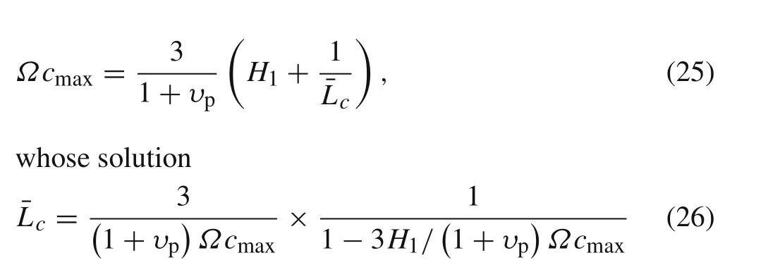


This expression indicates that the dimensionless critical length¯L c=L c/δtcis a function ofΩcmaxandυp.Reducing the maximum volumetric expansion and the Possion’s ratio of the active layer could be two effective ways to suppress the delamination.
Figure 7 shows the critical size for delamination varies with the maximum volumetric strain.The approximate results are given by Eq.(27a)and(27b)while the semi analytical results are given by Eqs.(15a)–(17d)and Eq.(20)with the delamination length equals zero exactly,and the parameters are set as¯E=0.2,¯h=0.5,and¯σtc=2×10⁻⁴.It is found that the approximate results have great accuracy especially whenΩcmax?0.75.Thus,this approximation is more appropriate for the material with large volumetric change,such as silicon.
5 Conclusions
Delamination of the active layer bonded on the substrate was investigated by plane analysis.The evolution of delamination and the initiation time to delamination was studied in plane strain and plane stress simultaneously.The plane strain condition is found more prone to delamination than the plane stress condition.
The impact of seven key parameters,i.e.,the length of the active layer¯L,the thickness of the active layer¯h,the electrochemical load factor¯i,the Poisson’s ratio of the active layerυpand the substrateυs,the Young’s modulus ratio¯E,and the cohesive strength¯σtcwere evaluated in both the evolution of delamination and the critical time.It was found that Poisson’s ratio of substrate,elastic modulus ratio,and cohesive strength have insignificant effect on both the critical time and the delamination process.However,the smaller sizes of the active layer,charging velocity,and Poisson’s ratio of the active layer can effectively prevent the delamination.
Finally,the critical size for delamination was obtained as a function of maximum volumetric strainΩcmaxand Poisson’s ratio of active layerυp.The deviation of approximate analytical expression with the semi-analytical solution can be neglected whileΩcmax?0.75.
AcknowledgementsThe project was supported by the National Natural Science Foundation of China(Grants 11332005 and 11172159)and the Shanghai Municipal Education Commission of China(Grant 13ZZ070).
Appendix A:Coefficient functions in the governing equations
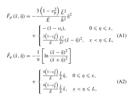
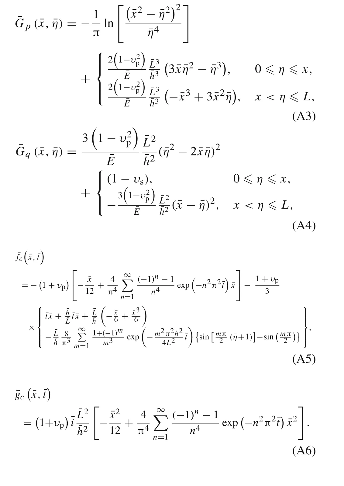
Appendix B:Numerical method for solving the derived integral equations
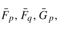
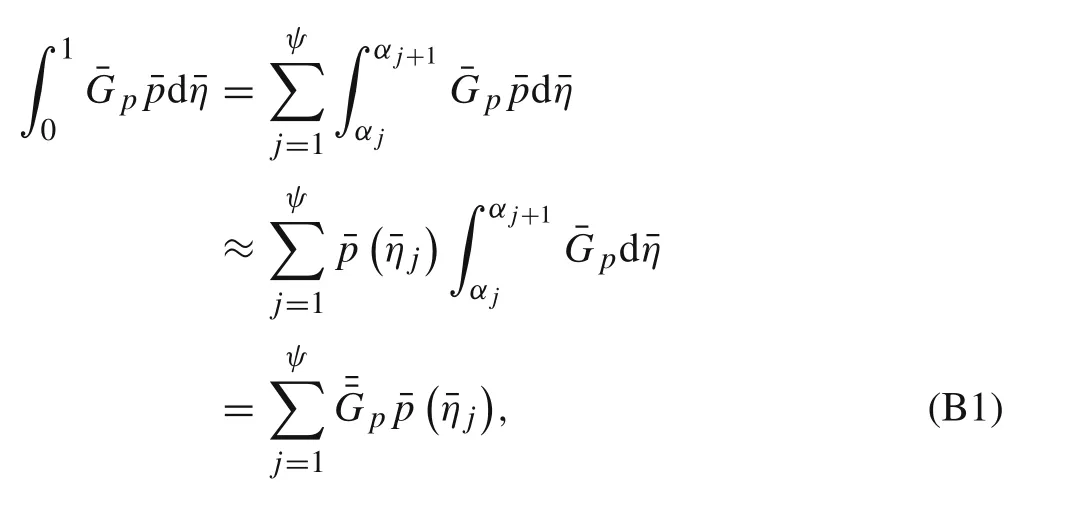
In order to numerically solve the integral Eqs.(15a)–(17d)and Eq.(20),the length of the active layerLis divided intoψsegments.¯xi=¯ηi=xi/L=(2i−1)/2ψdenotes the mid-point of theith line segment.Hence,the interface can be partitioned into three zones:damage-free zone(1?i?ς),cohesive zone(ς+1?i?ξ),and debonding zone(ξ+1?i?ψ).Numerical integration of the integrals in Eqs.(15a)–(17d)and Eq.(20)can be made by the first integral mean value theorem.Take?10¯G p¯pd¯ηas an example
Consequently,there are 2ψ+1 unknowns including¯p?¯ηj?,¯q?¯ηj?,and¯L0in 2ψ+1 linear algebraic equations.For a given time,the stresses and the lengths of the cohesive zone and debonding zone can be obtained by solving the system of linear equations repeatedly.In the first iteration,initial trial values of segment numbersςandξare assumed and the corresponding interfacial stresses can be obtained by solving the equations.Accordingly,ςandξcan be adjusted by comparing the interfacial stresses with cohesive strengths,as well as comparing the open/sliding displacements with critical values.Then the second iteration begins.The iteration will not stop untilςandξno longer change.
1.Chen,J.:Recent progress in advanced materials for lithium ion batteries.Materials 6,156–183(2013)
2.Dahn,J.R.,Zheng,T.,Liu,Y.,et al.:Mechanisms for lithium insertion in carbonaceous materials.Science 270,590(1995)
3.Boukamp,B.A.,Lesh,G.C.,Huggins,R.A.:All-solid lithium electrodes with mixed-conductor matrix.J.Electrochem.Soc.128,725–729(1981)
4.Baggetto,L.,Niessen,R.A.,Roozeboom,F.,et al.:High energy density all-solid-state batteries:a challenging concept towards 3D integration.Adv.Funct.Mater.18,1057–1066(2008)
5.Chan,C.K.,Peng,H.,Liu,G.,et al.:High-performance lithium battery anodes using silicon nanowires.Nat.Nanotechnol.3,31–35(2008)
6.Maranchi,J.P.,Hepp,A.F.,Evans,A.G.,etal.:Interfacial properties of the a-Si/Cu:active-inactive thin-film anode system for lithiumion batteries.J.Electrochem.Soc.153,A1246–A1253(2006)
7.Kasavajjula,U.,Wang,C.,Appleby,A.J.:Nano-and bulk-siliconbased insertion anodes for lithium-ion secondary cells.J.Power Sources 163,1003–1039(2007)
8.Howe,J.Y.,Burton,D.J.,Qi,Y.,etal.:Improving microstructure of silicon/carbon nanofiber composites as a Li battery anode.J.Power Sources 221,455–461(2013)
9.Li,H.,Huang,X.,Chen,L.,et al.:Ahigh capacity nano Sicomposite anode material for lithium rechargeable batteries.Electrochem.Solid State 2,547–549(1999)
10.Kim,H.,Han,B.,Choo,J.,et al.:Three-dimensional porous silicon particles for use in high-performance lithium secondary batteries.Angew.Chem.Ind.Ed.120,10305–10308(2008)
11.Souquet,J.L.,Duclot,M.:Thin film lithium batteries.Solid State Ion.148,375–379(2002)
12.Xiao,X.,Liu,P.,Verbrugge,M.W.,et al.:Improved cycling stability of silicon thin film electrodes through patterning for high energy density lithium batteries.J.Power Sources 196,1409–1416(2011)
13.Maranchi,J.P.,Hepp,A.F.,Kumta,P.N.:High capacity,reversible silicon thin-film anodes for lithium-ion batteries.Electrochem.Solid State 6,A198–A201(2003)
14.Haftbaradaran,H.,Xiao,X.,Verbrugge,M.W.,et al.:Method to deduce the critical size for interfacial delamination of patterned electrode structures and application to lithiation of thin-film silicon islands.J.Power Sources 206,357–366(2012)
15.Pal,S.,Damle,S.S.,Patel,S.H.,et al.:Modeling the delamination of amorphous-silicon thin film anode for lithium-ion battery.J.Power Sources 246,149–159(2014)
16.Liu,M.:Finite element analysis of lithiation-induced decohesion of a silicon thin film adhesively bonded to a rigid substrate under potentiostatic operation.Int.J.Solids Struct.67,263–271(2015)
17.Prezas,P.D.,Somerville,L.,Jennings,P.,et al.:Effect of fast charging of lithium-ion cells:Performance and post-test results.SAE Technical Paper,2016-01-1194(2016)
18.Lu,B.,Song,Y.,Guo,Z.,et al.:Modeling of progressive delamination in a thin film driven by diffusion-induced stresses.Int.J.Solids Struct.50,2495–2507(2013)
19.Lu,B.,Song,Y.C.,Guo,Z.S.,etal.:Analysis of delamination in thin film electrodes under galvanostatic and potentiostatic operations with Li-ion diffusion from edge.Acta Mech.Sin.29,348–356(2013)
20.Cheng,Y.-T.,Verbrugge,M.W.:Evolution of stress within a spherical insertion electrode particle under potentiostatic and galvanostatic operation.J.Power Sources 190,453–460(2009)
21.Crank,J.:The Mathematics of Diffusion.Oxford University Press,Oxford(1979)
22.Camacho,G.T.,Ortiz,M.:Computational modelling of impact damage in brittle materials.Int.J.Solids Struct.33,2899–2938(1996)
23.Woelke,P.B.,Shields,M.D.,Hutchinson,J.W.:Cohesive zone modeling and calibration for mode I tearing of large ductile plates.Eng.Fract.Mech.147,293–305(2015)
24.Tvergaard,V.,Hutchinson,J.W.:The relation between crack growth resistance and fracture process parameters in elastic–plastic solids.J.Mech.Phys.Solids 40,1377–1397(1992)
25.Li,J.,Dozier,A.K.,Li,Y.,et al.:Crack pattern formation in thin film lithium-ion battery electrodes.J.Electrochem.Soc.158,A689–A694(2011)
26.Lei,G.H.,Sun,H.S.,Ng,C.W.W.:Relative displacements in semiinfinite plane.Rock Soil Mech.35,1224(2014)
27.Lu,B.,Song,Y.,Zhang,J.:Time to delamination onset and critical size of patterned thin film electrodes of lithium ion batteries.J.Power Sources 289,168–183(2015)
28.Szczech,J.R.,Jin,S.:Nanostructured silicon for high capacity lithium battery anodes.Energy Environ.Sci.4,56–72(2011)
- Acta Mechanica Sinica的其它文章
- A node-based smoothed point interpolation method for dynamic analysis of rotating flexible beams
- Numerical algorithm for rigid body position estimation using the quaternion approach
- A general solution for one dimensional chemo-mechanical coupled hydrogel rod
- Micromechanics of substrate-supported thin films
- Generalized mixed finite element method for 3D elasticity problems
- Influence of layer orientation and interlayer bonding force on the mechanical behavior of shale under Brazilian test conditions

