
A Multi-Layered Model for Heat Conduction Analysis of Thermoelectric Material Strip
2018-04-08 06:04:07ShenghuDingandQingnanLiu
Shenghu Ding and Qingnan Liu
1 Introduction
Thermoelectric (TE) materials are becoming increasingly important, which represents a promising material technology for energy harvesting from heat sources. TE energy converters have received much attention, because these solid-state devices may generate electricity by harvesting waste thermal energy, thereby improving power generation the efficiency of the system [Glosch, Ashauer, Pfeiffer et al. (1999); Venkatasubramanian,Siivola, Colpitts et al. (2001); Riffat and Ma (2003); Xiao, Hangarter, Yoo et al. (2008);Boulanger (2010)]. The conversion efficiency of TE materials is directly related to its figure of meritwhere s is the Seebeck coefficient,the electric conductivitythe thermal conductivity andthe temperature [Mahan and Sofo(1996); Gao, Du, Zhang et al. (2011)]. Due to extensive researched [Mansfeld and Lang(1994); Kwon, Ju, Yoon et al. (2009); Brinzari, Damaskin, Trakhtenberg et al. (2014)]the thermoelectric properties of bulk materials are well known. However, to improve the thermoelectric figure of merit ZT in bulk materials is still difficult due to the inherent inter-couplings. Recently, a nonlinear asymptotic homogenization theory to consider the effective behavior of layered thermoelectric composite with coupled transport of electricity and heat has been investigated by Yang et al. [Yang, Ma, Lei et al. (2013)].Yang et al. [Yang, Xie, Ma et al. (2012)] also considered the effective thermoelectric behavior of layered heterogeneous medium. The results show that the effective thermoelectric figure of merit of a composite medium can be higher than all of its constituents even in the absence of size and interface effects, in contrast to previous studies.
The material’s response under thermal-electric loads should be studied for the better understanding of the structural strength, reliability and lifetime of the thermoelectric materials and structures. The first-principles transport calculations forusing the linearized-augmented plane-wave method and the relaxation time approximation are presented by Thonhauser et al. [Thonhauser, Scheidemantel, Sofo et al. (2003)]. Using three methods, the fracture toughness of undopedand indium dopedthermoelectric skutterudites are studied by Eilertsen et al. [Eilertsen,Subramanian and Kruzic (2013)]. Using the Fourier model, thermoelectric behaviors of these materials have been studied [Antonova and Looman (2005); Pérez-Aparicio, Taylor and Gavela (2007)]. Under transient operating conditions, the dynamic thermal behavior of thermoelectric generators and refrigerators under the effect of the hyperbolic heat conduction model have been described by Alata et al. [Alata, Al-Nimr and Naji (2003)].Although many papers have focused on the thermoelectric properties and mechanical properties of such materials, very few researchers have paid attention to crack problems in thermoelectric media under mechanical, thermal or electrical loads. Since thermoelectric materials are typically brittle semiconductors, they are always subject to crack or micro-crack damage under mechanical, thermal or electrical loads. Using the thermal shock resistance test, a crack was found to initiated on aspecimen surface with one quenching cycle [Isoda, Shinohara, Imai et al. (1999)]. The slow crack growth study was considered by Schmidt et al. [Schmidt, Case, Giles III et al. (2012)] in which the length of Vickers radial indentation cracks was monitored as a function of time in room air. Using the finite element analysis, the role of the dimensions of micro-thermoelectric generators, including the length of the thermoelements, thickness of the substrates, and cross-sectional area of the thermoelements are studied by Jang et al.[Jang, Han and Kim (2011)].
By assuming constant material propertiesandin the functioning temperature range, the crack problem in a medium possessing coupled thermoelectric effect under thermal-electric loads has been considered by Zhang et al. [Zhang and Wang (2013)].Based on the complex variable method, Song et al. [Song, Gao and Li (2015)] solved the two-dimensional problem of a crack in thermoelectric materials. It can be found that the fields of heat flow, electric current, and stress exhibit traditional square-root singularity at the crack tip. Furthermore, there is a linear relationship between the stress intensity factor and the heat flux, but there is a non-linear relationship between the stress intensity factor and the electric current. Consider two kinds of crack surface conditions, the crack problem in a thermoelectric material is studied by Song et al. [Song and Song (2016)].Zhang et al. [Zhang and Wang (2016)] considered the interface crack problem in a layered thermoelectric or metal/thermoelectric material based on the nonlinear governing equations and complex variable method. Using Fourier transform technique and singular integral equation method, a theoretical model to analyze the thermoelectric conversion efficiency of a cracked thermoelectric material with finite height and width is studied by Zhang et al. [Zhang and Wang (2017)]. Wang et al. [Wang and Wang (2017)] studied a theoretical model for the thermoelectric coupling analysis of thermal materials with an inclined elliptic hole and the extended problem of an elliptic hole under biaxial loading.However, the material coefficient matrix in general depends on temperature from experiments and microscopic statistical mechanics [Zabrocki, Müller and Seifert (2010)].Such an idealization offers a considerable amount of simplification to the analysis.Therefore, it is very important to develop analytical models for thermoelectric material with arbitrarily varying properties. In this paper, we develop a multi-layered model for approximate analysis of thermoelectric material whose properties may vary arbitrarily and solve the problem of a crack in a thermoelectric material strip under the electric flux and energy flux loading conditions. The Fourier integral transform technique and singular integral equation method are employed to solve the mixed boundary value problem. The thermal solutions could provide useful information to improve the design of thermoelectric devices.
2 Problem formulation and multi-layered model
Consider a thermoelectric material strip (TEMs) that is infinite alongand has a finite thickness. The strip contains a through crack of lengththat is parallel to the edges of the strip, as shown in Fig. 1. The crack surface boundary conditions are regarded as electrically and thermally fully impermeable. In the present paper, the TEMs is loaded by a remote electric fluxand a remote energy fluxas considered.
The constitutive relations for thermoelectric material can be written in the following form
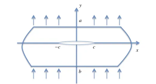
Figure 1: The heat conduction analysis of thermoelectric material strip
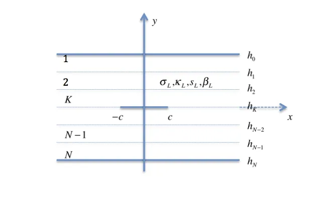
Figure 2: The multi-layered model of the thermoelectric material strip
It is assumed that material parametersandare arbitrary functions of y, which makes the boundary value problem based on governing field equations nonlinear and untractable. In order to simulate the arbitrary variations ofanda multi-layered model can be employed. The TEMs is divided intosub-layers with the crack on thesub-interface (L may be any integer between 1 and N). The analytical model is shown in Fig. 2. We use a superscript or a subscript L to represent the layer number, counting from the top surface of the structure. The L-th layer is located between the region y=h(L−1)and y=hL. Since we consider the continuously varied material properties, if N is sufficiently large, the material properties of the adjacent two layers will nearly the same. Therefore, the crack tip singularity will be same as that of a crack in an isotropic homogeneous thermoelectric medium.
For each layer as an isotropic homogeneous thermoelectric medium, the constitutive equations can be transferred to the following form

and governing field equations
The continuities or jumps of electric flux, energy flux, electrochemical potential and absolute temperature at the sub-interfaces or crack face y=hLcan be written as
where Δµ(K)and ΔT(K)are the electrochemical potential and absolute temperature jumps across the crack face; H() is the Heaviside function, and δLKis the Kronecker delta.
We consider the present problem as the superposition of the following two sub-problems:(a) the TEMs free of crack subjects to applied loads on the surface, inducing electric flux and energy flux at y=hK; and (b) the crack face is loaded under electric flux and energy flux with the surface free. It should be noted that we would only consider the second problem because the first problem contributes nothing to the singular fields at the crack tips.
The boundary conditions on the crack plane are stated as

The upper and lower surfaces of the strip are free of electric flux and energy flux

The equilibrium equation can be obtained in each layer by applying the constitutive Eq.
(2) to governing field Eq. (3). We have

Apply Fourier integral transform to Eq. (9), the general solution of the electrochemical potential and absolute temperature are given by

where ‘~’ standing for the Fourier integral transform, ALi(L=1,2,3,...N;i=1−4) are unknown coefficients.
The absolute temperature, electrochemical potential, electric flux and energy flux are given by

in which
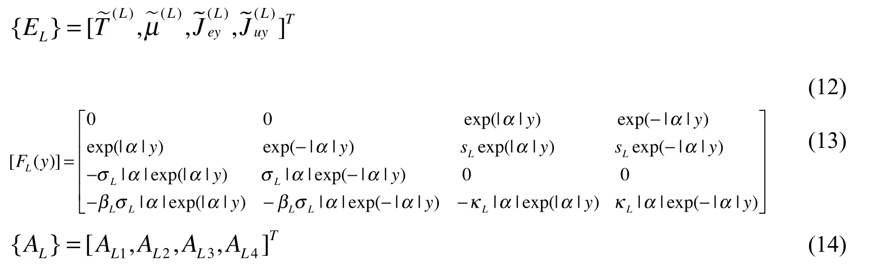
where the superscript “T” standing for transposition of matrix.
The interfacial conditions between neighboring sub-layers in the transformed domain can be obtained as

From the boundary conditions given in (8), we obtain

with
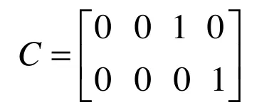
Eqs. (15) and (16) constitute 4N independent algebraic equations which can be solved to uniquely determine 4N unknown coefficients ALi(L=1,2,...N;i=1−4). The obtained results can be written in a matrix form

where [ML(α)] can be analytically or numerically obtained by solving Eqs. (15) and(16).
Inserting Eq. (17) into Eq. (12) and applying the inverse Fourier transform, one obtains

From Eq. (7), we have

From Eqs. (19) and (7), one obtains

The continuity condition for the absolute temperature and electrochemical potential on the bonded part along the extended crack line yields

It can be found that Eqs. (20) and (21) are dual integral equations for the TEMs crack problem.
3 Cauchy singular integral equation
In order to solve the dual integral Eqs. (20) and (21), the following dislocation density functions are introduced

Applying Fourier transformation with respect to x on both sides of Eq. (22), one obtains


Substituting Eq. (23) into Eqs. (20) and (21) leads to the following integral equations The singular nature of the kernels functions can be determined by examining the asymptotic behavior of the kernels functions as α approaches to infinity

in which

Considering Eq. (24), and using the relation

The following Cauchy singular integral equation can be obtained

in which

From Eq. (28) it is clear that at the crack tipsthe unknown functions,φ1(x) and φ2(x)have the square-root singularity at the crack tips, we can express them as

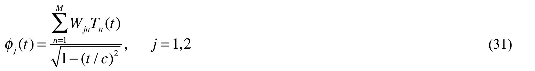
where the bounded unknown function Φ1(t) and Φ2(t) are Hölder-continuous. The function Φ1(t) and Φ2(t) can be expressed in terms of infinite series of orthogonal polynomials as follows

where Tn(t)(n=0,1,…) is the Chebyshev polynomials of the first kind.
By substituting Eqs. (29) and (30) into Eq. (25), and from the orthogonality conditions of Tn(t), it can be shown that W10=W20=0. Truncating the infinite series, the density function can be approximated as
By substituting Eq. (31) into Eq. (28) and using the following relations
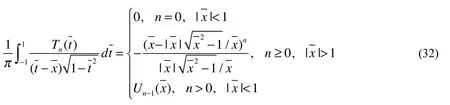

The unknown constants Wqn(n=1,2,...M;q=1,2) can be determined by using a collocation technique to convert Eq. (33) into a set of linear simultaneous equations, and then solving numerically for Wqn. The collocation points selected in this study are

which are the roots of Chebyshev polynomials.
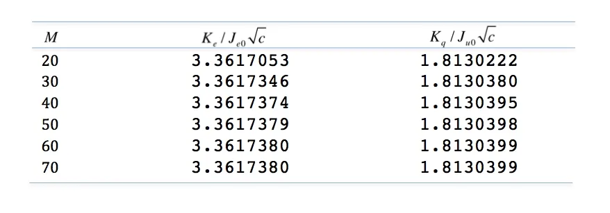
Table 1: Normalized EFIF and TFIF for different M under uniform electric flux and uniform energy flux loading conditions
4 Intensity factors
By using the Plemelj formula, the term with Cauchy singularity in (28) can be expressed as
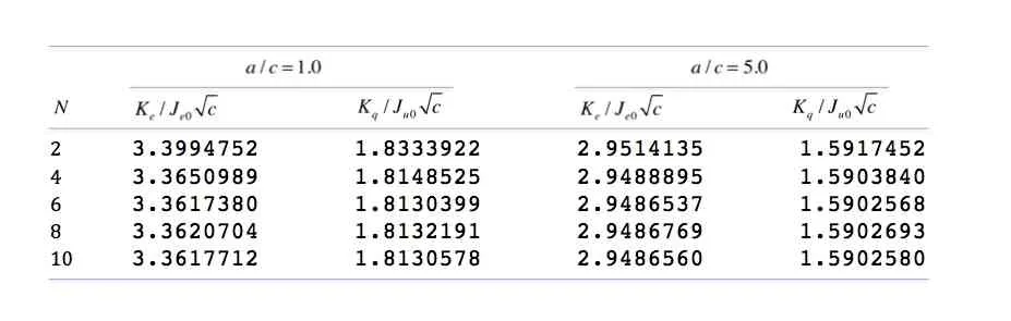
Table 2: Normalized EFIF and TFIF for different N under uniform electric flux and uniform energy flux loading conditions
The asymptotic expressions for the electric flux and energy flux at the crack tip can be expressed as

where Keand Kuare electric flux intensity factor (EFIF) and energy flux intensity factor, respectively.
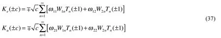
By substituting Eqs. (28), (31), (33) and (35) into (36), the electric flux intensity factor and energy flux intensity factor can be calculated by
Defining the thermal flux intensity factor (TFIF) Kqin the conventional manner [Jang,Han and Kim (2011)]
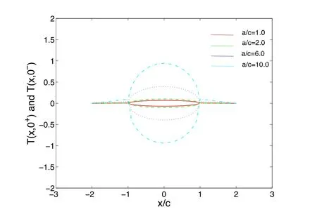
Figure 3: Influences of a/c on the temperatures T(x,0+) and T(x,0−) on the crack surface and crack extend line y=0 for multi-layered model, b=a
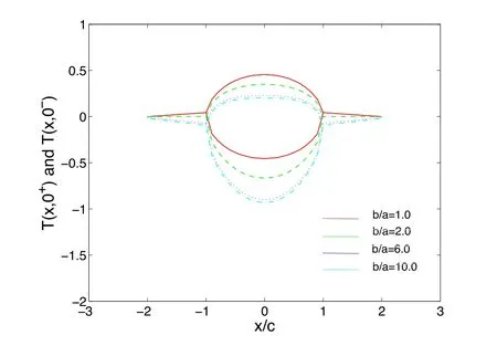
Figure 4: Influences of b/a on the temperatures T(x,0+) and T(x,0−) on the crack surface and crack extend line y=0 for multi-layered model, a/c=1.0
5 Numerical examples and discussion
As demonstrating examples, we consider the TEMs with a crack of length 2c subjected to a uniform electric flux loading Jey(x)=Je0and energy flux loading Juy(x)=Ju0.The geometry of the problem being examined is shown in Fig.1. The material properties can be found in Yang et al. [Yang, Xie and Ma (2012)]. The crack is located along the interval −1≤ x/c≤1.
In order to obtain enough accurate results and to avoid too much CPU time, we need to choose properly total number of the discrete points (i.e. M in Eq. (33) and the number of sub-layers(i.e. N in Eq. (15)). Tab. 1 shows the normalized EFIF and TFIF for different M under electric flux and energy flux loading conditions when N=6. Tab.2 lists the normalized EFIF and TFIF for different N under electric flux and energy flux loading conditions when M=50. The results are given in Tabs. 1 and 2 where the EFIF and TFIF have been normalized byandrespectively. From Tab. 1, it can be found that sufficiently accurate results can be obtained when M≥50. From Tab. 2, we can answer another question, that is, how many sub-layers should the TEMs be divided into so that enough accurate results can be obtained? By selecting different values of N, it can be seen that N=6 or 8 can yield results which may be considered sufficiently accurate. So for this example, we will choose the number of the sub-layers to be 6.
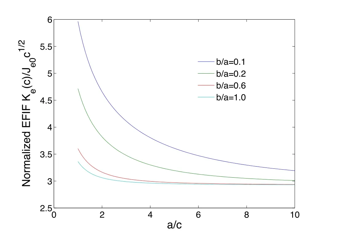
Figure 5: Variations of normalized EFIF with a/c under uniform electric flux and uniform energy flux loading at the crack-face for multi-layered model
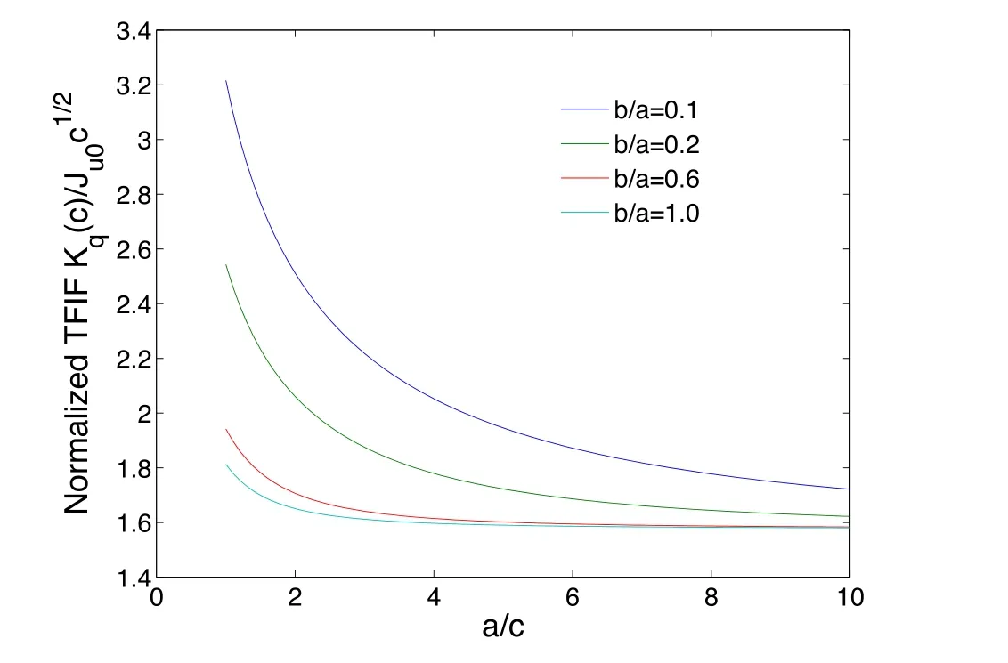
Figure 6: Variations of normalized TFIF with a/c under uniform electric flux and uniform energy flux loading at the crack-face for multi-layered model
Figs. 3 and 4 show the temperature distribution along the crack plane y=0+ and y=0−. It can be found that the temperature jump across the crack becomes more pronounced as the a/c increases when b=a. And with the increasing of b/a, the temperature jump across the crack becomes more pronounced when a/c=1.0.
Figs. 5 and 6 have presented the normalized EFIF and TFIF by the multi-layered model with N=6 as a variation of b/a under electric flux and energy flux loading conditions. It can be found that normalized EFIF and TFIF decrease with the increasing of b/a. As an increase of a/c, normalized EFIF and TFIF decrease gradually and tend to a constant when a/c→∞. Meanwhile, the normalized EFIF is always greater than the normalized TFIF for the same value of a/c.
6 Concluding remarks
A multi-layered model for heat conduction analysis of a TEMs with a Griffith crack under the electric flux and energy flux load is developed in the present paper. The crack is parallel to edges of the strip. The materials parameters of the TEMs vary continuously in an arbitrary manner. The thermally and electrically impermeable crack surface assumptions are used in this paper. To derive the solution, the TEMs is divided into several sub-layers with different material properties. The mixed boundary problem is reduced to a system of singular integral equations which are solved numerically. By selecting different values of N , it can be seen that N=6 or 8 can yield results which may be considered sufficiently accurate. The temperature jump across the crack becomes more pronounced with the increasing of a/c or b/a. It can be found that the near-tip electric flux and thermal flux always possess a characteristic square-root singularity in terms of the distance from the crack tip. The electric flux intensity factor, energy flux intensity factor and thermal flux intensity factor are obtained. The normalized EFIF and TFIF decrease with the increasing of a/c or b/a.
Financial support from the outstanding youth cultivation project of Ningxia higher education (NGY2017002), is gratefully acknowledged.
Reference
Alata, M.; Al-Nimr, M.; Naji, M.(2003): Transient behaviour of a thermoelectric device under the hyperbolic heat conduction model. International Journal of Thermophysics, vol. 24, 1753-1768.
Antonova, E.; Looman, D.(2005): Finite elements for thermoelectric device analysis in ANSYS. International Conference on Thermoelectrics, pp. 215-218.
Boulanger, C.(2010): Thermoelectric material electroplating: a historical review.Journal of Electronic Materials, vol. 39, 1818-1827.
Brinzari, V.; Damaskin, I.; Trakhtenberg, L.; Cho, B. K.; Korotcenkov, G.(2014):Thermo-electrical properties of spray pyrolyzed indium oxide thin films doped by tin.Thin Solid Films, vol. 552, pp. 225-231.
Eilertsen, J.; Subramanian, M. A.; Kruzic, J. J.(2013): Fracture toughness of Co4Sb12and ln0.1Co4Sb12thermoelectric skutterudites evaluated by three methods.Journal of Alloys and Compounds, vol. 552, pp. 492-498.
Glosch, H.; Ashauer, M.; Pfeiffer, U.; Lang, W.(1999): A thermoelectric converter for energy supply. Sensors and Actuators, vol. 74, pp. 246-250.
Gao, J. L.; Du, Q. G.; Zhang, X. D.; Jiang, X. Q.(2011): Thermal stress analysis and structure parameter selection for a Bi2Te3-based thermoelectric module. Journal of Electronic Materials, vol. 40, pp. 884-888.
Isoda, Y.; Shinohara, Y.; Imai, Y.; Nishida, I.; Ohashi, O.(1999): Thermal shock resistance and thermoelectric properties of boron doped iron disilicides. Japan Institute Metals, vol. 63, pp. 391-396.
Jang, B.; Han, S.; Kim, J. Y.(2011): Optimal design for micro-thermoelectric generators using finite element analysis. Microelectronic Engineering, vol. 5, pp. 775-778.
Kwon, S. D.; Ju, B. K.; Yoon, S. J.; Kim, J. S.(2009): Fabrication of bismuth telluride-based alloy thin film thermoelectric devices grown by metal organic chemical vapor deposition. Journal of Electronic Materials, vol. 38, pp. 920-924.
Mansfeld, M.; Lang, W.(1994): Cooling of silicon structures using an integrated peltier element. Sensors and Materials, vol. 6, pp. 1-8.
Mahan, G. D.; Sofo, J. O.(1996): The best thermoelectric. Applied Physical Sciences,vol. 93, pp. 7436-7439.
Pérez-Aparicio, J.; Taylor, R.; Gavela, D. (2007): Finite element analysis of nonlinear fully coupled thermoelectric materials. Computational Mechanics, vol. 40, pp. 35-45.
Riffat, S. B.; Ma, X. L.(2003): Thermoelectrics: a review of present and potential applications. Applied Thermal Engineering, vol. 23, pp. 913-935.
Schmidt, R. D.; Case, E. D.; Giles III, J.; Ni, J. E.; Hogan, T. P.(2012):Room-temperature mechanical properties and slow crack growth behavior ofMg2Si thermoelectric materials. Journal of Electronic Materials, vol. 41, pp. 1210-1216.
Song, H. P.; Gao, C. F.; Li, J. Y.(2015): Two-dimensional problem of a crack in thermoelectric materials. Journal of Thermal Stresses, vol. 3, pp. 325-337.
Song, H. P.; Song, K.(2016): Electric and heat conductions across a crack in a thermoelectric material. Journal of Theoretical & Applied Mechanics, vol. 1, pp. 83-98.
Thonhauser, T.; Scheidemantel, T. J.; Sofo, J. O.; Badding, J. V.; Mahan, G. D.(2003): Thermoelectric properties of Sb2Te3under pressure and uniaxial stress.Physical Review B, vol. 68, pp. 338-344.
Venkatasubramanian, R.; Siivola, E.; Colpitts, T.; O'quinn, B.(2001): Thin-film thermoelectric devices with high room-temperature figures of merit. Nature, vol. 413, pp.597-602.
Wang, P.; Wang, B. L.(2017): Thermoelectric fields and associated thermal stresses for an inclined elliptic hole in thermoelectric materials. International Journal of Engineering Science, vol. 119, pp. 93-108.
Xiao, F.; Hangarter, C.; Yoo, B.; Rheem, Y.; Lee, K. H. et al.(2008): Recent progress in electrodeposition of thermoelectric thin films and nanostructures. Electrochimica Acta,vol. 53, pp. 8103-8117.
Yang, Y.; Xie, S. H.; Ma, F. Y.; Li, J. Y.(2012): On the effective thermoelectric properties of layered heterogeneous medium. Journal of Applied Physics, vol. 111, pp. 703.
Yang, Y.; Ma, F. Y.; Lei, C. H.; Liu, Y. Y.; Li, J. Y.(2013): Nonlinear asymptotic homogenization and the effective behavior of layered thermoelectric composites. Journal of the Mechanics and Physics of Solids, vol. 61, pp. 1768-1783.
Zabrocki, K.; Müller, E.; Seifert, W.(2010): One-dimensional modeling of thermogenerator elements with linear material profiles. Journal of Electronic Materials,vol. 39, pp. 1724-1729.
Zhang, A. B.; Wang, B. L. (2013): Crack tip field in thermoelectric media. Theoretical and Applied Fracture Mechanics, vol. 66, pp. 33-36.
Zhang, A.; Wang, B.(2016): Temperature and electric potential fields of an interface crack in a layered thermoelectric or metal/thermoelectric material. International Journal of Thermal Sciences, vol. 104, pp. 396-403.
Zhang, A. B.; Wang, B. L.; Wang, J.; Du, J. K.; Xie, C. et al.(2017): Thermodynamics analysis of thermoelectric materials: influence of cracking on efficiency of thermoelectric conversion. Applied Thermal Engineering, vol. 127, pp. 1442-1450.
 Computer Modeling In Engineering&Sciences2018年3期
- Computer Modeling In Engineering&Sciences的其它文章
- Fast Solving the Cauchy Problems of Poisson Equation in an Arbitrary Three-Dimensional Domain
- Stability Analysis of Network Controlled Temperature Control System with Additive Delays
- Numerical Investigation of Convective Heat Transfer and Friction in Solar Air Heater with Thin Ribs
- AdaBoosting Neural Network for Short-Term Wind Speed Forecasting Based on Seasonal Characteristics Analysis and Lag Space Estimation
- Bifurcation-Based Stability Analysis of Electrostatically Actuated Micromirror as a Two Degrees of Freedom System