Numerical Investigation of Convective Heat Transfer and Friction in Solar Air Heater with Thin Ribs
Sanjay K. Sharma and V. R. Kalamkar,
1 Introduction
Solar air heaters are passive heat exchangers used to extract the heat from the solar radiations. These are basically ducts of high aspect ratio (Width/Height, W/H). Ribs are provided in the underside of the absorber plate to increase the heat transfer from these ducts. Several authors have conducted the performance testing of these devices with numerical and experimental approach. A three-dimensional (3D) simulation was carried out [Kumar and Saini (2009)], with arc shaped geometry on the absorber plate of solar air heater using RNG k-ε turbulence model. The numerical and experimental results were in close agreement and obtained the highest Nusselt number ratio (Nur/Nu0) of 1.7. The metal grit ribs of circular, square and rectangular cross section at angle of attack (α)=600were used on the absorber plate [Karmare and Tikekar (2010)]. They reported an enhancement of 30% in the heat transfer than the smooth plate and the best performance was found at α=58°.A 3D numerical investigation, with multi V- shaped ribs were carried out by Jin et al. [Jin, Zhang, Wang et al. (2015)]. They used various span wise V-rib numbers for constant relative roughness pitch (P/e), relative roughness height (e/Dh), and α for different Reynolds numbers (Re). The maximum thermo-hydraulic performance parameter (THPP) of 1.93 was reported. A 3D simulation with different non-uniform cross-sectioned ribs in the solar air heater was investigated [Singh, Singh, Hans et al.(2015)]. They used square, circular, trapezoidal and saw toothed ribs with RNG k-ε turbulence model. The maximum (Nur/Nu0) and friction factor ratio (fr/f0) were obtained for the saw tooth and trapezoidal ribs of 1.78 and 3.58, respectively. A 3D numerical simulation with V shape, Multi V shape and Multi V shape with gap ribs were investigated numerically [Kumar (2014)]. The results with RNG k-ε turbulence model had good agreement with the experimental results. The (Nur/Nu0) of 1.7, 4.7 and 5.6 was obtained for the ribs used, respectively. The numerical study with spherical turbulence turbulators was performed by Manjunath et al. [Manjunath, Vasudeva and Sharma(2017)]. The effect of diameter (D) and relative pitch ratio (P/D) on the thermal efficiency and the thermo-hydraulic performance were studied. An improvement of 23.4% thermal efficiency and 2.5 times increase of Nur/Nu0at P/D=3, at Re of 23560. Authors like[Fedele, Manca, Nardini et al. (2008); Ansari and Geisari (2013)] have pointed out that the use of thin ribs is always beneficial as far as heat transfer enhancement is concerned.The present work deals with the 3D numerical investigations of the high aspect ratio(W/H=10) solar air heater with thin ribs on the absorber plate. The one pitch length contains two transverse continuous and two truncated ribs in between. The novelty of work lies in the use of multiple thin transverse continuous and truncated ribs on the absorber plate. The main objective of the present CFD analysis is:
i. To investigate the effect of geometrical (P/e, e/Dh) and flow parameters (Re) on the heat transfer and flow characteristics.
ii. To find out the optimal rib configuration of combination of thin transverse and
2 Computational domain and grid generation
The computational domain here is a rectangular duct of height and width of 30 and 300 mm respectively and the pitch (P) ranges from (24-36). The maximum and minimum height of the rib is 3 mm and 2 mm. The thickness of the rib is constant of 1 mm. The rib arrangement consists of two truncated ribs placed with equal truncation of 5% from both the sidewalls. The present simulation deals with nine different rib combinations of thin transverse continuous and truncated ribs. Each rib configuration has been simulated on seven different values of Reynolds number ranging from 4000-16000. Sixty-three sets of CFD simulations has been performed for the geometrical (P/e and e/Dh) and flow conditions (Re) at constant heat flux of 1000 W/m2, to investigate the heat and flow friction behaviour. The simulations have been carried out for the range of Re=4000-16000, which is generally used for solar air heaters [Hans, Saini and Saini (2009); Kumar,Saini and Saini (2014)].

Figure 1: Computational fluid domain
The computational domain has been created using ICEM CFD (Version 16.2). The nonuniform structured meshing has been done to get more accurate results. The rib placement is shown in the Fig. 2 for three different pitch (P) lengths.

Figure 2: Different pitch (P) length domains

Table 1: Details of rib configuration
Grid generation is the most important task for any simulation. Fine grids are generated to ensure the accurate flow computations. For the present 3D computational domain, nonuniform hexahedral mesh is generated using ICEM CFD V 16.2. The complete computational domain has fine mesh generated near the walls keeping the wall element's spacing of Y+<1 such that the viscous sub layer may be resolved completely.The non-uniform grid generation can be seen in Fig. 3
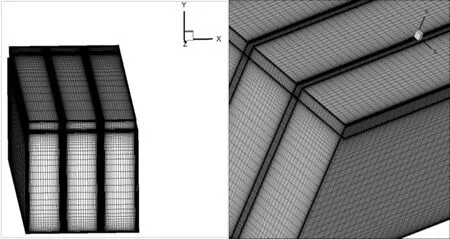
Figure 3: Meshing of the computational domain
Grid independence test was carried out to minimize the computational time. Three different nodes were considered 1239492, 1449378 and 1837520 for grid independence.The Nurand frobtained was 28.163, 28.201, 28.123 and 0.052189, 0.05169, 0.05176. The difference between 1449378 and 1837520 nodes for Nurand frwas found to be less than 1%. So, 1449378 grids were used for the simulation. However, the nodes were gradually increased to maintain the desired Y+ criteria at the wall.
2.1 Boundary conditions
The boundary conditions imposed on the computational domain has been given in Fig. 1.
These boundary conditions can be summarised as:
(i) At inlet section (in X direction)

(ii) At the top wall (Absorber plate)

(iii) Side and Bottom walls
No slip condition and
Adiabatic

2.2 Governing equations
The forced turbulent flow and heat transfer in the ribbed solar air heater duct are described by the sets of governing equations of continuity, momentum and energy conservation. For the three-dimensional, steady state, forced turbulent flow, incompressible fluid assuming no radiation heat transfer, the governing equations are as follows:
The governing equation used in the heat and fluid flow is as follows:
Continuity equation:

Where uiis the velocity components in the Cartesian coordinate system with its coordinates xi
Momentum equation:

Energy Equation:

Where μtis the eddy viscosity and I, j, k=1, 2 and 3.
The RNG k-ε model was used to model the turbulence. The transport equations for turbulent kinetic energy ‘k’ and its rate of dissipation ‘ε’ used in the RNG k-ε model are as follows:

The eddy viscosity in Eqs. (10) and (11) is computed as

The model constant values are:
Cmu=0.0845; C1epsilon=1.42; C2epsilon=1.68 and wall Prandtl No.=0.85
The turbulent prandtl number (Prt) value is taken as 0.85, Pr=0.71 for air. The physical properties of the working fluid air are ρ=1.225 kg/m3, μ=1.7895*10-5kg/ms and Cp=1006.43 J/kg K.
The average Nusselt number (Nur) for the ribbed solar air heater is calculated by,

The friction factor is estimated using the Shear wall stress. Also known as Darcy friction factor

For Numerical analysis, the Nusselt number for smooth duct (Nus) of a solar air heater is obtained using the Dittus-Boelter equation [McAdams (1942)],

Similarly, Friction factor for smooth duct (fs) of a solar air heater can be calculated using the Modified Blasius equation, given as.

2.3 Solution method
The three-dimensional model of the computational domain has been solved by RANS model. The continuity equation, energy equations and the Navier-stokes equations has been solved using ANSYS FLUENT. The computational domain has been resolved with RNG (Renormalization) k-ɛ turbulence model with enhanced wall treatment as wall function. The Y+<1 to resolve the turbulent sub layer efficiently. The discretization of the governing equation, SIMPLE (Semi implicit method) algorithm developed by Patankar[Patankar (1980)] for pressure and velocity coupling has been used. Second order upwind scheme is used for the solving all the transport equations. The convergence criteria of 10-5,10-8and 10-4have been set for the continuity, velocity and energy equations. The default values of the thermo physical properties of air given in the FLUENT are used for the simulation with periodic boundary condition for one Pitch length (P) in the direction of flow. Also, the symmetric wall is provided in the Z direction. The operating parameters for the CFD analysis are enlisted in the Tab. 2, shown below.
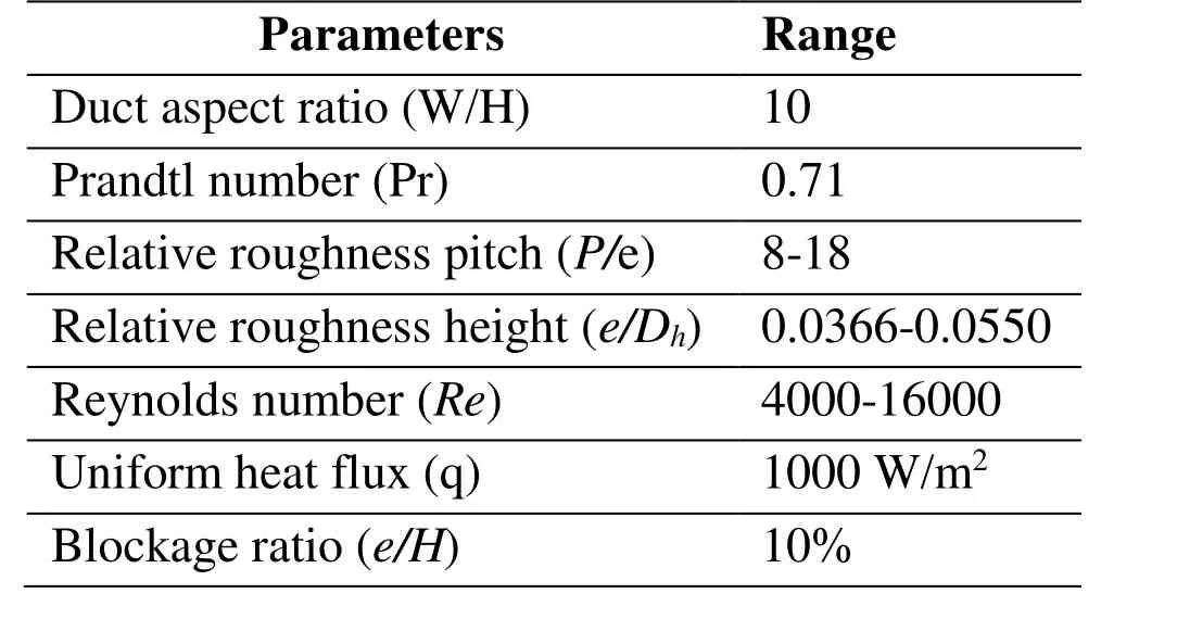
Table 2: Range of parameters
3 Results and discussion
The three-dimensional numerical simulation of the solar air heater has been investigated for the average heat transfer and fluid flow characteristics. The effect of the geometrical and flow parameters associated with the ribs has been discussed in this section.
3.1 Heat transfer and fluid flow characteristics
The heat transfer characteristics are presented in the form of average Nusselt number (Nur)of the ribbed duct for the different geometrical and flow conditions. The Nurvalue for each simulation has been evaluated using Eq. (1). Fig. 4 shows the effect of P/e on the average Nurfor different values of Reynolds number. The presence of ribs enhances the Nurin comparison to the smooth duct (Nu0). Turbulence is created due to presence of the ribs, which causes the heat transfer enhancement. The velocity increases with the increase in Re which in turn increases the heat transfer. As the Re increases the ribs starts protruding from the laminar sub layer of the turbulent zone. So, the laminar sub layer thickness starts decreasing causing an increase in the heat transfer. These ribs also prevent the formation of the boundary layer and increase the turbulent intensity.
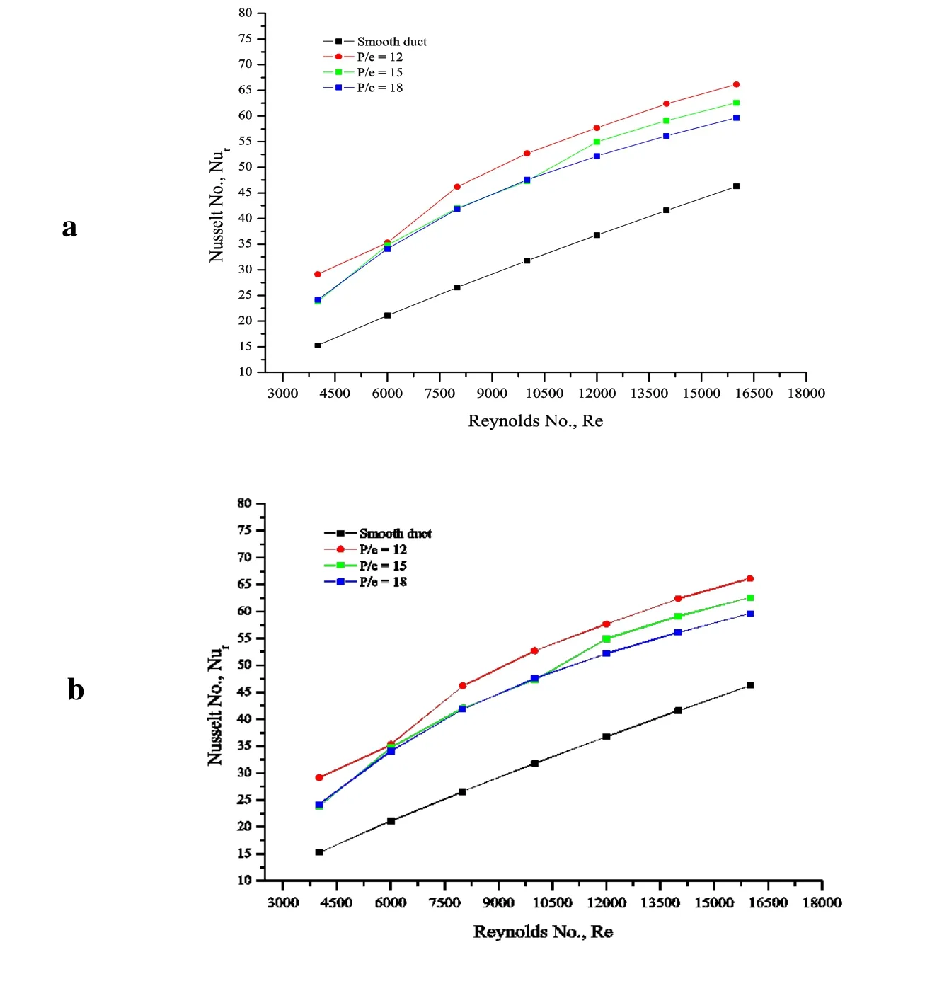
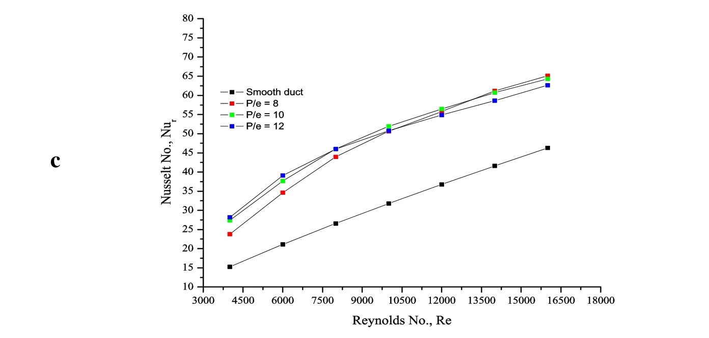
Figure 4: Effect of P/e on average Nur (a) e/Dh=0.0366, (b) e/Dh=0.0456 (c) e/Dh=0.055
Fig. 5 shows the effect of P/e on the enhancement of average Nurfor the different e/Dhvalues. The presence of thin transverse continuous and the truncated ribs show significant enhancement of the Nurfor all the Re values over the smooth duct. The reattachment and recirculation of the separated flow due to presence of ribs and mixing of the primary and secondary flows contribute in the increased heat transfer from the surface. Another way of interpretation to understand the effect of P/e on Nur. These effects have been investigated for the constant relative roughness height. It can be inferred from Fig. 5 that for most of the cases the average Nurdecreases as the P/e increases. The increases in P/e value can reduce the chances of reattachment due to the formation of new boundary layer.This leads to reduction in the heat transfer from the ribbed surface. Also, the turbulent intensity gets reduces due to increase in P/e, further reducing the average Nurvalues. As the e/Dhvalue increases (0.0458, 0.055), we can observe an increase in the Nurat lowest Re. This may cause local Nurenhancement at certain location. However, this effect diminishes as Re increases causing further decrease of Nurwith increase in P/e. As the P/e values are increasing, the chances of reattachment of the separated flow from the tip of the rib increase particularly at higher e/Dhand lower Re. This reattachment of flow and vortex shedding phenomenon can increase the heat transfer locally, thereby increasing the Nur. The higher e/Dhvalues entrap more volume.
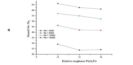
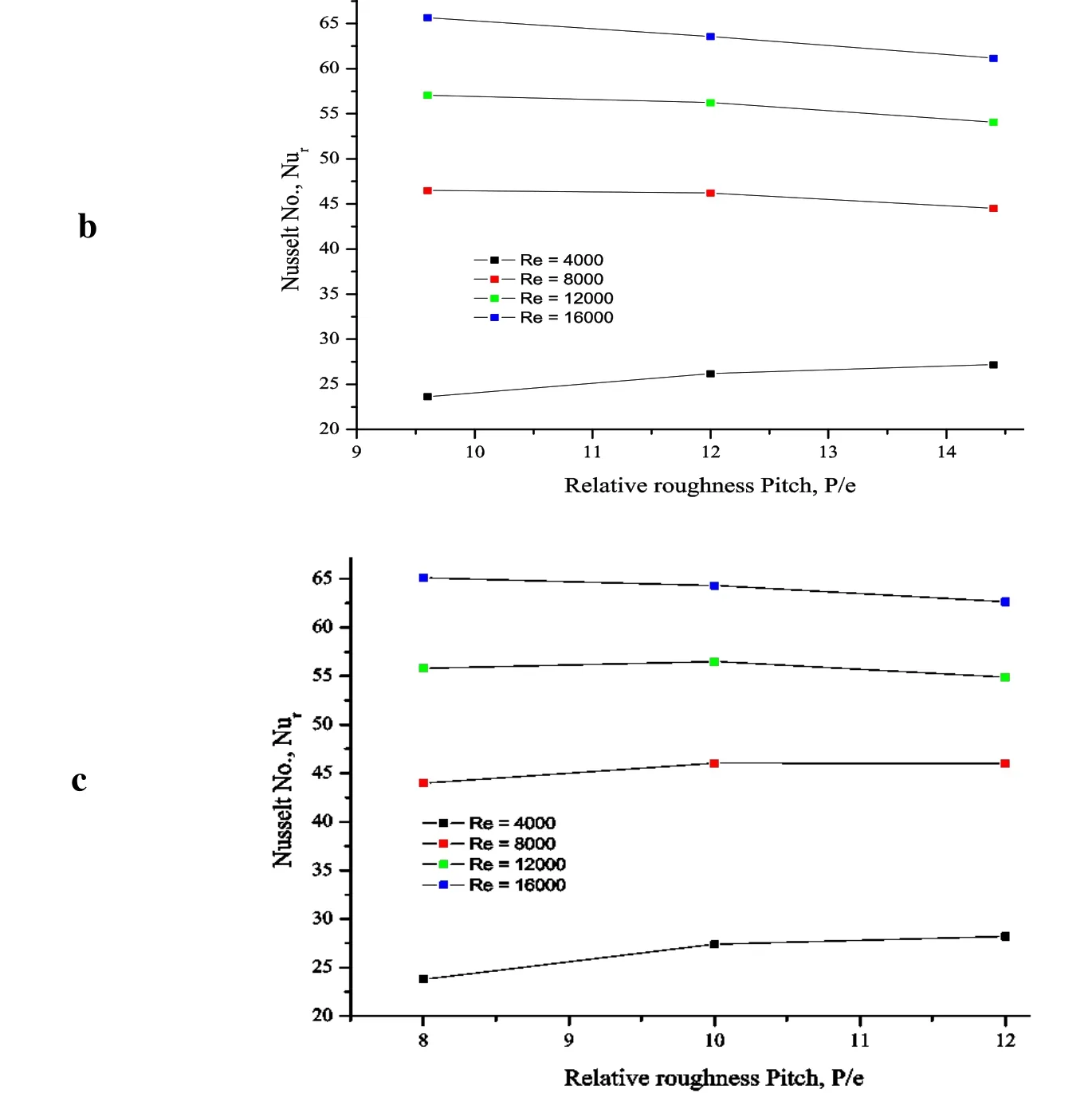
Figure 5: Effect of Re on P/e at (a) e/Dh=0.0336 (b) e/Dh=0.0458 (c) e/Dh=0.0550
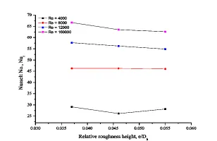
Figure 6: Effect of Re on e/Dh at P/e=12
The effect of Reynolds number on relative roughness height (e/Dh) for the average Nusselt number can be seen in Fig. 6. in of air between the ribs causing better mixing of flows thereby increasing the Nur. The heat transfer effects are investigated for a constant value of P/e. The decrease of Nurwith an increase in e/Dhcan be observed for all values of P/e. As the rib height (e) increases for a given P/e, the chances of reattachment of the free shear layer after separating at the leading edge of the rib diminish, which reduces the heat transfer effects. The maximum heat transfer can be observed at a particular e/Dhvalue for the range of parameters considered. For the present investigation, the optimum value of e/Dhis 0.0366. In the similar manner, the effect of average Nurvalues has been investigated at constant P/e and the range e/Dhvalues for different Re as shown in Fig. 7.The average Nurvalues increases with an increase in the Re. This is due to vigorous mixing of primary and secondary flows, reattachment and vortex shedding in between the ribs. In addition to these factors, the turbulence intensity increases with the increase in Re further contributes in heat transfer enhancement. The details of normalized Nusselt number (Nur/Nu0) for the range of parameters considered in the present configuration of thin transverse continuous and truncated ribs is enlisted in Tab. 3.

Figure 7: Nur vs. Re at P/e=12 and different e/Dh
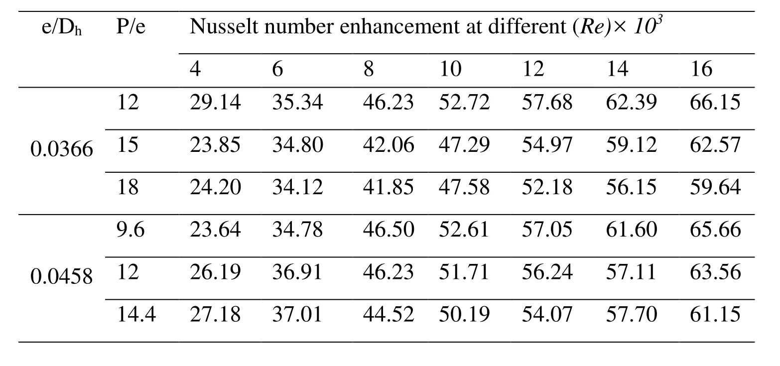
Table 3: Nusselt number enhancement for different rib configuration

8 23.80 34.62 43.97 50.65 55.81 61.17 65.12 0.05510 27.38 37.66 46.05 51.95 56.48 60.72 64.33 12 28.19 39.11 46.00 50.78 54.88 58.62 62.66
The previous work found the maximum increase in the Nusselt number ratio at P/e value of≥10. Verma et al. [Verma and Prasad (1999)] has also recommended the value of P/e of 12 for better reattachment points giving higher heat transfer. Here, in the present investigations also, the maximum heat transfer is obtained at P/e of 12. The comparative results from the previous work are given in Tab. 4.
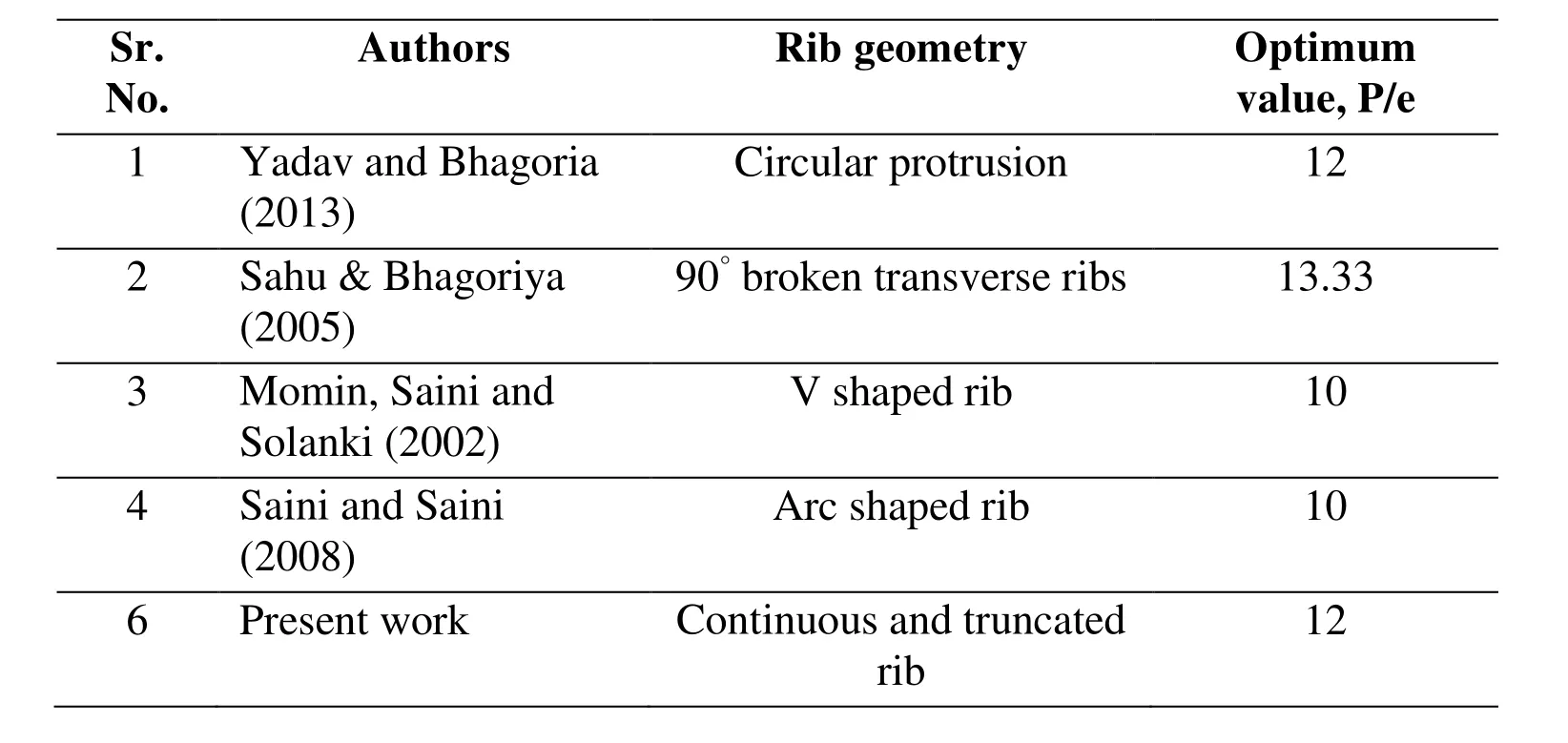
Table 4: Optimum P/e values
The above discussion shows a significant enhancement of the heat transfer with the employment of thin transverse continuous and truncated rib on the absorber plate of the solar air heater. The temperature contours, turbulent intensity, turbulent kinetic energy,velocity fields and vortex formation images obtained for such investigations are also helpful in understanding the thermal enhancement. They reflect the qualitative measurement of such properties to understand the various flow structures associated with such type of rib arrangement on the absorber plate. Figs. 8-12 deal with different qualitative measurement of heat transfer and flow structure measurements. The temperature contours at different Re (4000, 10000 and 16000) can be seen in Fig. 8 for constant P/e and e/Dhof 8 and 0.0366 respectively.
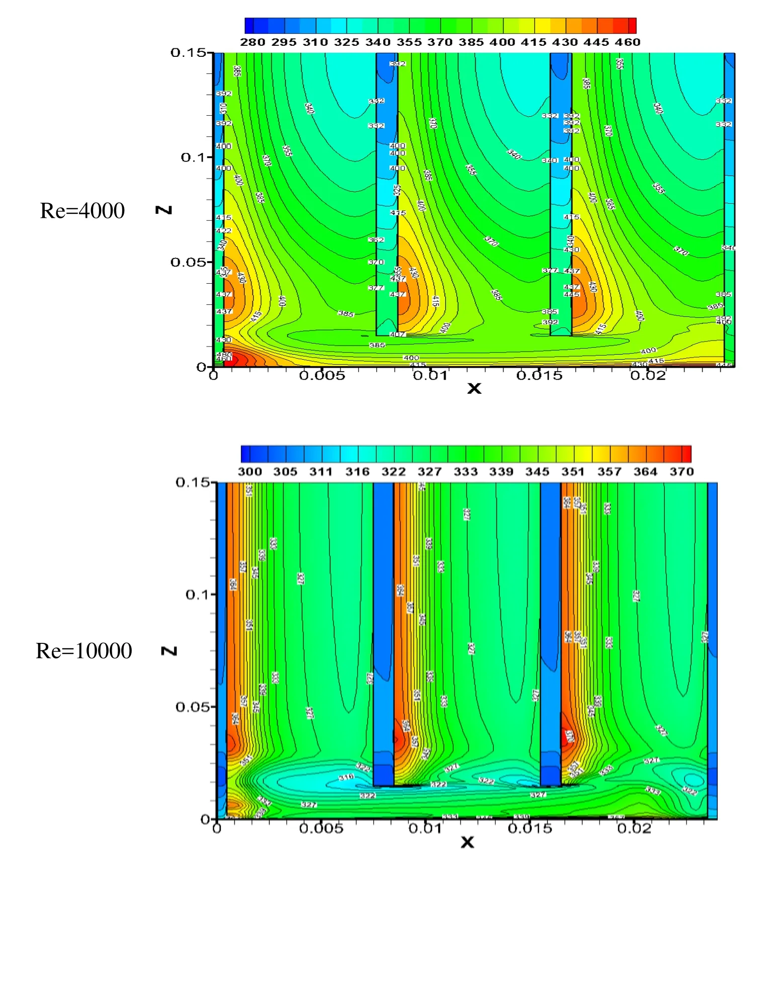

Figure 8: Temperature contours for different Re and P/e=8, e/Dh=0.0366
The decrease in the average temperature of the absorber plate is evident as an increase in Reynolds number. As it increases, the convective heat transfers increases so the average temperature over the ribbed surface decreases. The temperature contours can be observed at the backside of rib in the upstream direction due to low air movement. These high temperature zones reduce the convective heat transfer to the flowing air, thus decreasing the overall heat transfer from the ribbed surface. Such idle or non-active zones are also visible to the corner of sidewalls, and its area reduces with the increase in Reynolds number. Fig. 9 shows the temperature contours of the ribbed surface at different relative roughness pitch, constant Reynolds number and relative roughness height of 10000 and 0.0458, respectively. As relative roughness pitch increases, the average temperature of the fluid over the ribbed surface decreases, showing decrement in the heat transfer from the flowing air over it. The results are in accordance to the previous investigators of this area where they have shown the optimum heat transfer at P/e of 12. The other flow characteristics as turbulent kinetic energy and velocity magnitude also give important information on the flow and are shown in Figs. 10-11. The variation of the turbulent kinetic energy contours as a function of Reynolds number is shown in Fig. 10. Turbulent kinetic energy shows the intensity of turbulence in the flow. It measures the mean kinetic energy on the unit mass basis. It is strongly related to the shear layer. It is extracted from the mean flow to larger eddies and dissipate through smaller ones. The turbulent kinetic energy increases with the increase in Reynolds number. The k-ε model uses,for estimating the turbulence viscosity. The higher value of k will lead to higher heat transfer. The turbulence intensities are reduced near the wall, and high turbulence intensity is found between the ribs, near the front of the rib top. The increase in the turbulence intensity can be observed in the Fig. 10 with increase in Reynolds number.The increase in reattachment points over the absorber plate also causes to increase the average heat transfer (Nur). The effect of the velocity magnitude can be observed in Fig.11 at constant P/e of 9.6 and e/Dhof 0.0456 and different Re. The velocity magnitude increases as the Re increases. It shows the mean velocity of the velocities in X, Y and Z directions.
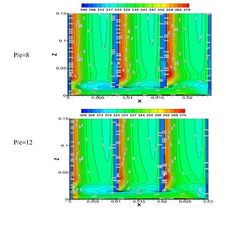
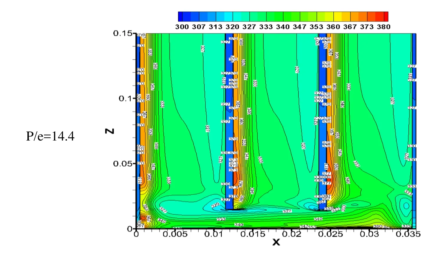
Figure 9: Temperature contours for different P/e
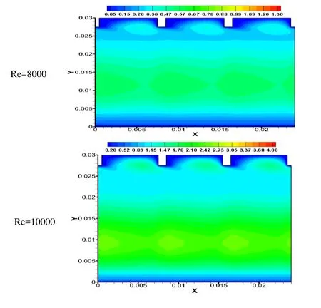

Figure 10: Turbulent kinetic energy at different Re and P/e=9.6, e/Dh=0.0456
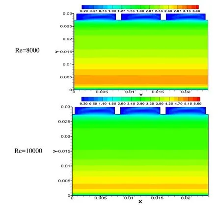
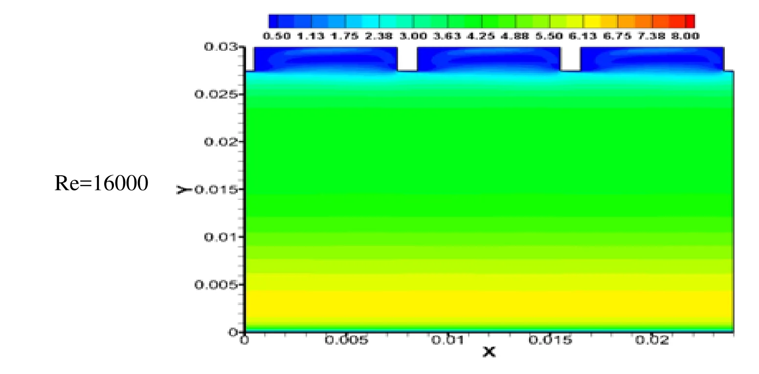
Figure 11: Velocity magnitude at various Re
Vortices formation is an inherent characteristic of the turbulent flows in ribbed ducts. The vortex size increases with the increase in e/Dh. We can see the larger sized vortex in the space between the ribs in the flow direction. The secondary vortex can also be seen in the Fig. 12 along the backside of the ribs in the upstream direction. The secondary flow along the rib promotes mixing of the flow near the walls, enhancing the heat transfer from the surface.
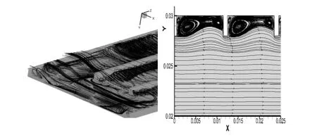
Figure 12: Vortices formation
4 Pressure drop characteristics
The numerical results of the flow friction characteristics in artificially roughened solar air heater with transverse continuous and truncated rib roughness on the absorber plate is presented in the form of an average friction factor (fr). The frfor each simulation has been evaluated using Eq. (3).
4.1 Effect of Reynolds number
The variation of the friction factor with Reynolds number for different values of relative roughness pitch (P/e) and relative roughness height (e/Dh) can be seen in Figs. 13 (a), (b)& (c). The frdecreases for an increase in Re because of the suppression of viscous sublayer for fully developed turbulent flow in the duct. The maximum value of the average fris found to be 0.0386 for the relative roughness pitch of 8 and for relative roughness height of 0.0550 at 4000 Re. The maximum enhancement of the average frhas been found to be 4.57 times that of smooth duct for the range of parameters investigated. The values of the friction factor for the ribbed duct are higher due to more of ribs for a unit pitch length. There is an increase in the friction factor value after Re of 6000, the shortly rise in the value is due the high wall shear stresses. Re of 8000 onwards the friction factor values decreases due to lowering of drag forces on the ribbed surface.
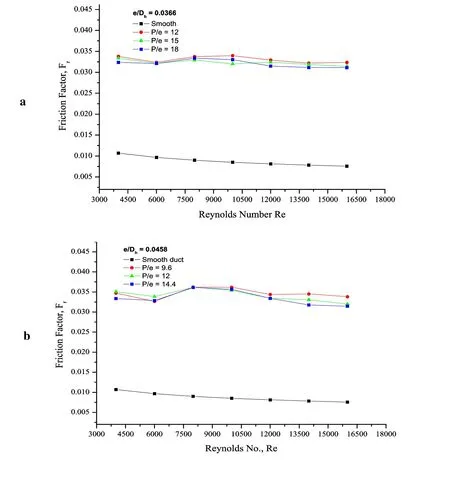
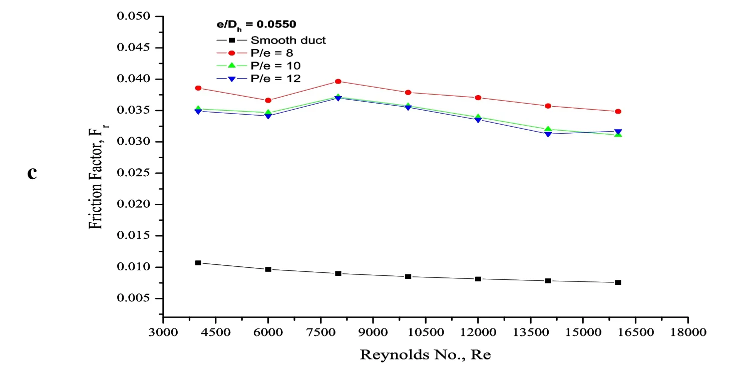
Figure 13: Fr vs. P/e for different Re and (a) e/Dh=0.0366 (b) e/Dh=0.00.0458 (c)e/Dh=0.055
4.2 Effect of relative roughness height
Effect of the e/Dhon the fris shown in Fig. 14. The frdecreases with the increase in Re for different values of e/Dh. As the e/Dhincreases, the frvalues go on increasing due to more resistance caused to the flow due to increase in blockage of the duct. As the Re increases, the frgoes on decreasing due to suppression of laminar sub-layer in fully developed turbulent flow in the solar air heater.
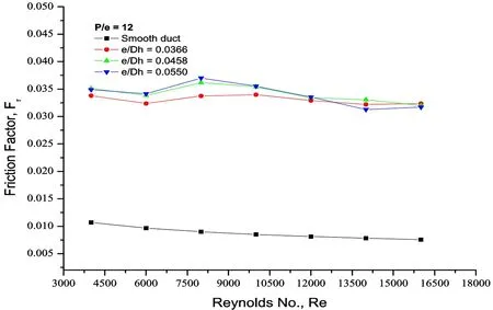
Figure 14: Fr vs. Re
The maximum fris found to be 0.0458 for the highest relative roughness height (e/Dh)and has been found maximum corresponding to relative roughness height of 0.042. Fig. 14 shows a plot of the fras a function of e/Dhfor different values of Re and for fixed value of e/Dhand P/e. The fr/f0which shows the increment of frover the smooth duct is given in the Tab. 5.
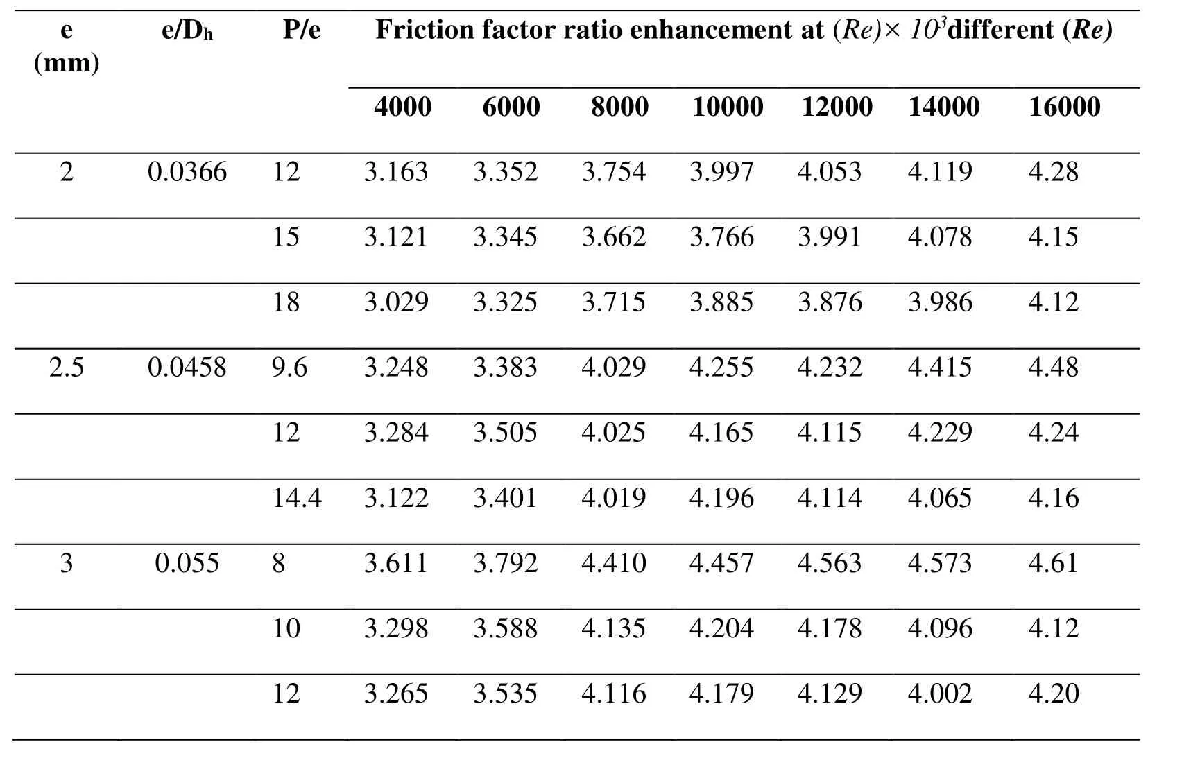
Table 5: Friction factor ratio (fr/f0) enhancement for different rib configuration
4.3 Effect of relative roughness pitch
Effect of the relative roughness pitch (P/e) on friction factor has been shown in Fig. 15.The fras a function of P/e for different values of Re (4000-16000) and for e/Dhof 0.0550 is shown in the figure. It is seen that the frvalues decrease with the increase in P/e for fixed value of e/Dhdue to the fewer number of ribs on the surface, causing lesser pressure drop. The drop in frat the higher Re onwards 8000 are more smooth and gradual. The maximum and minimum value of the froccurs at P/e of 8 and 12 with 0.0386 and 0.0317 respectively for the range of parameters investigate at e/Dh0.055.

Figure 15: Fr vs. P/e for different Re and e/Dh=0.055
5 Thermo-hydraulic parameters
The increase in relative roughness height increases the Nurand the fr. The rate of increase of fris higher than the Nur. It is, desirable to choose the roughness geometry such that the heat transfer is maximized while keeping the pumping losses at minimum. So the performance of the solar air heater is analyzed by considering both the heat transfer and friction factor enhancement. Fig. 17 shows the variation of the thermo-hydraulic performance parameter (THPP) with Re for all cases. This may be due to the missing of the re-attachment of free shear layer so rate of heat transfer enhancement is not proportionate to the increase in fr[Saini (1988)]. It may be concluded that as e increases,it starts protruding the laminar sub layer resulting in higher value of friction factor than the Nur.
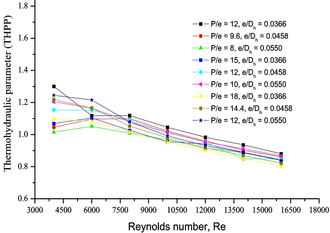
Figure 17: Thermo-hydraulic performance parameter vs. Reynolds No., Re
The present numerical investigation containing the rib combination gives the highest thermo-hydraulic performance parameter of 1.30 at relative roughness pitch of 12,relative roughness height of 0.0366 at 4000 Reynolds number. The maximum average Nusselt number enhancement of 1.91 over the smooth duct is obtained at the same geometrical and flow condition. It is found that the thermo hydraulic performance parameter values vary between 0.80 and 1.30 for the range of parameters investigated.
6 Conclusion
In this article a three-dimensional numerical simulation of a ribbed solar air heater having combination of transverse continuous and truncated ribs on the absorber plate of a solar air heater has been carried out. The numerical simulation predicts the heat transfer and flow friction characteristics. The effect of geometrical parameters P/e, e/Dhand flow parameters in the form of mass flow ratehas been studied for the range of parameters considered. The major conclusions of this work can be summarised as follows:
1. The CFD and experimental results are in good agreement.
2. The heat transfer and friction factor enhancement are an inherent characteristic of the ribbed solar air heaters.
3. The amount of enhancement of Nurand frdepends on the geometrical and flow conditions of the ribbed duct.
4. The maximum increase in the heat transfer (Nur) is 66.15 at Re of 16000, P/e of 12 and e/Dhof 0.0366.
5. The maximum friction factor increase over the smooth duct (fr/fo) of 4.57 is obtained at Re=4000, P/e of 8 e/Dhof 0.055.
6. The maximum enhancement ratio (Nur/Nus) obtained is 1.91 for the present case.
Reference
Alam, T.; Kim, M. H.(2016): Numerical study on thermal hydraulic performance improvement in solar air heater duct with semi ellipse shaped obstacles. Energy, vol. 112,pp. 588-598.
Ansari, M. R.; Geisari, R. A. (2013): Flow pattern changes in horizontal rectangular laterally ribbed ducts through alteration of rib thickness pitch. International Journal of Multiphase Flow, vol. 54, pp. 11-21.
Boukadoum, A. B.; Benzaoui, A.(2014): CFD based analysis of heat transfer enhancement in solar air heater provided with transverse rectangular ribs. Energy Procedia, vol. 50, pp. 761-772.
Chaube, A.; Sahoo P. K.; Solanki, S. C.(2006): Analysis of heat transfer augmentation and flow characteristics due to rib inclined continuous rib arrangement in a rectangular duct of solar air heater. Renewable Energy, vol. 31, pp 317-321.
Gupta, D.(1994): Investigations on fluid flow and heat transfer in solar air heaters with roughened absorbers. (Ph.D. Thesis). University of Roorkee, India.
Fedele, G.; Manca, O.; Nardini, S.; Ricci, D.; Masullo, G.(2008): Numerical investigation of air forced convection in channels with transverse ribs. Asme International Mechanical Engineering Congress & Exposition, pp. 939-947.
Gawande, V. B.; Dhoble A. S.; Zodpe D. B.; Chamoli S.(2016): A review of CFD methodology used in literature for predicting thermo-hydraulic performance of a roughened solar air heater. Renewable and Sustainable Energy Reviews, vol. 54, pp. 550-605.
Gawande, V. B.; Dhoble, A. S.; Zodpe, D. B.; Chamoli S.(2016): Experimental and CFD investigation of convection heat transfer in solar air heater with reverse L-shaped ribs. Solar Energy, vol. 131, pp. 275-295.
Handoyo, E. I.; Ichsani, D.; Prabowo; Sutardi (2016): Numerical studies on the effect of delta-shaped obstacles’ spacing on the heat transfer and pressure drop in vcorrugated channel of solar air heater. Solar Energy, vol. 131, pp. 47-60.
Hans, V. S.; Saini, R. P.; Saini, J. S.(2009): Performance of artificially roughened solar air heaters-a review. Renewable and Sustainable Energy Reviews, vol. 13, no. 8, pp.1854-1869.
Hans, V. S.; Saini, R. P.; Saini, J. S.(2010): Heat transfer and friction factor correlations for a solar air heater duct roughened artificially with multiple V-ribs, Solar Energy, vol. 84, pp. 898-911.
Jin, D.; Zhang, M.; Wang, P.; Xu, S.(2015): Numerical investigation of heat transfer and fluid flow in a solar air heater duct with multi V-shaped ribs on the absorber plate.Energy, vol. 89, pp. 178-190.
Karmare, S. V.; Tikekar, A. N.(2007): Heat transfer and friction factor correlation for artificially roughened duct with metal grit ribs. International Journal of Heat & Mass Transfer, vol. 50, pp. 4342-4351.
Karmare, S. V.; Tikekar, A. N.(2010): Analysis of fluid flow and heat transfer in a rib grit roughened surface solar air heater using CFD. Solar Energy, vol. 84, pp. 409-417.
Kumar, S.; Saini, R. P.(2009): CFD based performance analysis of a solar air heater duct provided with artificial roughness. Renewable Energy, vol. 34, pp. 1285-1291.
Kumar, A.(2014): Analysis of heat transfer and fluid flow in different shaped roughness elements on the absorber plate solar air heater duct. Energy Procedia, vol. 57, pp. 2102-2111.
Kumar, A.; Saini, R. P.; Saini, J.(2014): A review of thermo hydraulic performance of artificially roughened solar air heaters. Renew Sustain Energy Reviews, vol. 37, pp. 100-122.
McAdams, W. H.(1942): Heat Transmission. Mc Graw-Hill, New York.
Manjunath, M. S.; Vasudeva, K. K.; Sharma, Y. N.(2017): Numerical analysis of the influence of spherical turbulence generators on heat transfer enhancement of flat plate solar air heater. Energy, vol. 121, pp. 616-630.
Momin, A. M. E.; Saini, J. S.; Solanki, S. C.(2002): Heat transfer and friction in solar air heater duct with V-shaped rib roughness on absorber plate. International Journal of Heat and Mass Transfer, vol. 45, pp. 3383-3396.
Patankar, S. V.(1980): Numerical Heat Transfer and Fluid Flow. Hemisphere, Washington DC.
Prasad, B. N.; Saini, J. S.(1988): Effect of artificial roughness on heat transfer and friction factor in a solar air heater. Solar Energy, vol. 41, no. 6, pp. 555-560.
Saini, S. K.; Saini, R. P.(2008). Development of correlations for Nusselt number and friction factor for solar air heaterwith roughened duct having arc-shaped wire as artificial roughness. Solar Energy, vol. 82, pp. 1118-1130.
Sharma, S. K.; Kalamkar, V. R.(2015): Thermo-hydraulic performance analysis of solar air heaters having artificial roughness-a review. Renewable and Sustainable Energy Reviews, vol. 41, pp. 413-435.
Sharma, S. K.; Kalamkar, V. R.(2017): Experimental and numerical investigation of forced convective heat transfer in solar air heater with thin ribs. Solar Energy, vol. 147,pp. 277-291.
Singh, S.; Chander, S.; Saini, J. S.(2011): Heat transfer and friction factor correlations of solar air heater ducts artificially roughened with discrete V-down ribs. Energy, vol. 36,pp. 5053-5064.
Singh, S.; Singh, B.; Hans, V. S.; Gill, R. S.(2015): CFD (computational fluid dynamics)investigation on Nusselt number and friction factor of solar air heater duct roughened with non-uniform cross-section transverse rib. Energy, vol. 84, no. 1, pp. 509-517.
Thakur, D. S.; Khan, M. K.; Pathak, M. (2017): Performance evaluation of solar air heater with novel hyperbolic rib geometry. Renewable Energy, vol. 105, pp. 786-797.
Varun; Saini, S. K.; Singal, S. K.(2008): Investigation of thermal performance of solar air heater having roughness elements as a combination of inclined and transverse ribs on absorber plate. Renewable Energy, vol. 33, pp. 1398-1405.
Webb, R. L.; Eckert, E. R. G.(1972): Application of rough surface to heat exchanger design. International Journal of Heat & Mass Transfer, vol. 15, no. 9, pp. 1647-1658.
Xiao, H.; Chen, W.; Yan, B.(2015): Numerical simulation of heat transfer and friction in non-uniform wall roughness lattice with different roughness element shapes. Annals of Nuclear Energy, vol. 85, pp. 732-739.
Yadav, A. S.; Bhagoria, J. L.(2013): Heat transfer and fluid flow analysis of solar air heater: a review of CFD approach. Renewable and Sustainable Energy Reviews, vol. 23 pp. 60-79.
Yadav, A. S.; Bhagoria, J. L.(2013): Numerical investigation of flow through an artificially roughened solar air heater. International Journal of Ambient Energy, vol. 36, 87-100.
Yadav, A. S.; Bhagoria, J. L.(2013): Modelling and simulation of turbulent flows through a solar air heater having square-sectioned transverse rib roughness on the absorber plate. The Scientific World Journal. pp. 1-13.
Yadav, A. S.; Bhagoria, J. L.(2013): A CFD (Computational fluid dynamics) based heat transfer and fluid flow analysis of a solar air heater provided with circular transverse wire rib roughness on the absorber plate. Energy, vol. 55, pp. 1127-1142.
Yadav, A. S.; Bhagoria, J. L.(2014): A numerical investigation of square sectioned transverse rib roughened solar air heater. International Journal of Thermal Sciences, vol.79, pp. 111-131.
Yadav, A. S.; Bhagoria, J. L.(2014): A CFD based thermo-hydraulic performance analysis of an artificially roughened solar air heater having equilateral triangular sectioned rib roughness on the absorber plate. International Journal of Heat and Mass Transfer, vol. 70, pp. 1016-1039.
 Computer Modeling In Engineering&Sciences2018年3期
- Computer Modeling In Engineering&Sciences的其它文章
- Fast Solving the Cauchy Problems of Poisson Equation in an Arbitrary Three-Dimensional Domain
- A Multi-Layered Model for Heat Conduction Analysis of Thermoelectric Material Strip
- Stability Analysis of Network Controlled Temperature Control System with Additive Delays
- AdaBoosting Neural Network for Short-Term Wind Speed Forecasting Based on Seasonal Characteristics Analysis and Lag Space Estimation
- Bifurcation-Based Stability Analysis of Electrostatically Actuated Micromirror as a Two Degrees of Freedom System
