Bifurcation-Based Stability Analysis of Electrostatically Actuated Micromirror as a Two Degrees of Freedom System
Kuntao Ye, Yan Luo and Yingtao Jiang
1 Introduction
Electrostatically actuated torsional micromirror is widely utilized in various engineering or research fields due to its advantages of low energy consumption, simple structure and high scanning frequency [Koay and Rahim (2016)]. Like any other devices driven by electrostatic force, a torsional micromirror system’s top plate can be attracted to and physically get in touch with its bottom plate. This so-called pull-in phenomenon,whenever it occurs, is an indicator that the torsional micromirror system is at an unstable state.
The pull-in phenomenon in electrostatically driven systems is well researched for the development of micro-electro-mechanical systems (MEMS) technology. An early study of pull-in concerned only the static equilibrium [Zhang, Chau, Quan et al. (2001)]. Very quickly, it was realized that the pull-in of any electrostatically actuated MEMS device is related to bifurcation seen in a nonlinear system, exemplified in a study to characterize the pull-in instability of a MEMS device using the bifurcation diagram obtained from a simple model [Pelesko (2002)].
In general, study of the pull-in of a torsional micromirror has been carried out by either solving the static equilibrium equation and dynamic differential equation directly [Zhang,Chau, Quan et al. (2001); Zhao, Chen, Huang et al. (2005)], or applying phase space analysis. Through the latter approach, the bifurcation phenomenon of micromirror system can be identified right in the state/phase space by examining the state change of the system, and those state changes are found to be directly tied to the stability or instability of the system. Following the phase space analysis, Li et al. [Li, Xi and Hua (2011)] were able to mathematically reveal that the DMD system exhibits both the saddle node and the codimension bifurcations. Taghizadeh et al. [Taghizadeh and Mobki (2014)] analyzed an electrostatically driven double bottom plate torsional micromirror system in phase space using one-degree-of-freedom(1-DoF) dynamic model, and the system shows the saddle node and pitchfork bifurcations. Li et al. [Li, Duan, Ma et al. (2014)] proved that a sequence of Hopf bifurcation occurs at the equilibria in phase space analysis. Pratiher et al. [Pratiher (2014); Li and Zhang (2016)] studied the static and dynamic characteristics of electrostatically driven MEMS microbeam also in the phase space.
Although these studies have implicitly or explicitly recognized that subtle differences exist between the static pull-in and dynamic pull-in behaviors [Zhang, Yan, Peng et al.(2014)], no study yet is conducted to examine these differences through the phase space analysis, and it remains unexplored regarding how bifurcations of a MEMS micromirror system are linked to the dynamic pull-in.
Another drawback of all the bifurcation studies on MEMS micromirror system is attributed to the fact that they were all based on the 1-DoF model, which ignored the torsion-coupling effect. When this important effect is ushered in for more accurate analysis, a more complex two-degree-of-freedom (2-DoF) dynamics model needs to be developed and used.
To address the aforementioned problems in analyzing the pull-in phenomena of the electrostatically actuated MEMS torsional micromirror system with two voltage sources,the Newton-Euler method is applied to build a nonlinear 2-DoF dimensionless dynamic model, as detailed in Section 2. With the proposed 2-DoF model, both the static and dynamic characteristics of the micromirror can thus be studied through examining the static and the dynamic bifurcations in phase space, as reported in Sections 3 and 4. These results are compared with those obtained from the Hamiltonian method for undamped systems.
2 2-DoF Model for double bottom plate micromirror system
As shown in Fig. 1(a), the micromirror system is composed of two torsional cantilever beams, a micromirror surface, a top plate, two bottom plates, and two fixed anchors that sit on top of the silicon substrate. The width, length and thickness of the top plate are a, L,and tm, respectively. The thickness of the mirror is tAl. The width, length and thickness of the two cantilever beams are w, l, and tb, respectively. The size and position of the bottom plate are determined by a1and a2. The initial (rest) spacing between the top plate and the bottom plates is h.
As far as a micromirror system with a single bottom plate is concerned, a torsion micromirror model based on small angle approximation [Wetsel and Strozewski (1993)]could be used. If the bending-torsion coupling effect, resulting from a driving voltage applied to the plates, needs to considered, a vertical displacement has to be added into the model, along with the angular displacement, as the case in Huang’s work [Huang and Liu(2004)]. In the same token, for the double-bottom-plate torsional micromirror system driven by two voltages, V1and V2, the bending-torsion coupling effect cannot be ignored.Consequently, rotation of the micromirror will be reflected in the angle of rotation θ and the vertical displacement y, as illustrated in Fig. 1(b).
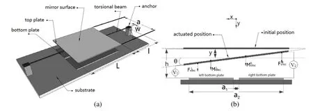
Figure 1: Schematic views of the torsional micromirror: (a) 3D view, and (b) crosssectional view
Since the lengths and widths of the top and bottom plates are much greater than the distance between the top and the bottom plates, the edge effect can be safely neglected[Huang and Liu (2004); Zhang, Meng and Chen (2007)]. The electrostatic forces between the top plate with unit length and the two respective bottom plates, hereinafter referred as the left bottom and the right bottom plates, are given below

where εris the relative dielectric constant (1 for air), and ε0is the dielectric constant of vacuum. If we integrate Eqs. (1) and (2) (see Eqs. (3) and (4)) and use small angle approximation (i.e. θ and sinθ are assumed to be equal when θ is small), the electrostatic force between a bottom plate and the top plate and the corresponding electrostatic torque can be expressed as Eq. (5) through Eq. (8).


The total electrostatic force and the total electrostatic torque of the top plate, at the angle of rotation θ and vertical displacement of y, are given in Eqs. (9) and (10).

In addition to electrostatic force, the micro-mirror system also is exerted on damping force Fdamp, elastic recovery force Felasand corresponding torques, as given in Eqs. (11)through Eq. (14) :

where Cyand Kyrepresent the damping factor and the stiffness of the vertical direction,respectively, and Cθand Kθrepresent the damping factor and stiffness of the torsional direction, respectively [Zhao, Chen, Huang et al. (2005)].
The micromirror system driven by an input voltage has a 2-DoF of coupling output: the torsional angle of θ and vertical displacement y. Following the Newton-Euler dynamics,the dynamics model of the micromirror system is constructed as Eq. (15):

Eq. (5) through Eq. (10) are substituted into Eq. (15), and then the variables are normalized by including the relationships defined in Eq. (16). The dimensionless twodegrees-of-freedom dynamic equation of the micromirror system is thereby obtained as given in Eq. (17).

where R0, R1are the equivalent damping coefficients, ω0is the natural angular frequency,and ω1is the natural frequency of the vertical bending movement. ω0and ω1can be calculated from the moment of inertia I, mass m, bending stiffness Kθ, and torsional rigidity Ky[Zhao, Chen, Huang et al. (2005)]. Note that p represents the ratio of the two driving voltages applied to the two bottom plates [Taghizadeh and Mobki (2014)].
As the system state variables are set to be x1=δ, x2=dδ/dτ, x3=φ, x4=dφ/dτ, the second order differential equations given in Eq. (17) can be transformed to the phase space equations which are the first order differential equations, as listed in Eq. (18).

As a dimensionless 2-DoF dynamics model, Eq. (18) can be used to compute the static pull-ins and bifurcations, dynamic pull-ins and bifurcations of the torsional micromirror in the phase space.
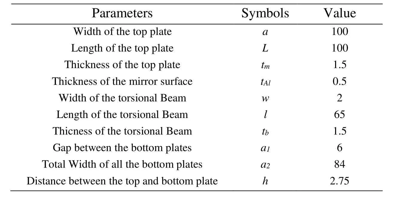
Table 1: Parameters of torsional micromirror (unit μm)
The coefficients in the analysis process are calculated from the parameters tabulated in Tab. 1, and values of the material properties are taken from the ones used in [Zhao, Chen,Huang et al. (2005)]. Note that if x1and x2in Eq. (18) take the value of zero, the system actually degenerates into a 1-DoF output system that does not consider the bendingtorsion coupling effect.
3 Static pull-in and bifurcation
As the driving voltage gradually reaches a critical value, beyond which the state of mechanical equilibrium is no longer maintained, the pull-in of the torsion micromirror will happen, along with a bifurcation phenomenon as predicted by the static analysis.This so-called static bifurcation and the static characteristics are studied through Hamiltonian method and numerical simulation in the phase space.
3.1 Hamiltonian analysis
When the 2-DoF system is in a static equilibrium state, not only does the elastic recovery moment balances the electrostatic moment, but the elastic recovery force and the electrostatic force in the vertical direction also need to balance each other. The static characteristics of the system thus can be analyzed using the Hamiltonian potential function that accounts for both balance of moments and balance of forces.
When damping R0=R1=0, the Hamiltonian [Azizi, Ghazavi, Khadem et al. (2013); Shang,Song and Wen (2016)] of the system described in Eq. (18) is given in Eq. (19).

The potential function is:

The equilibrium state of the system is computed by having [Elata and Bamberger (2006)]:

When the system is in equilibrium, it needs to satisfy the condition given in Eq. (22):

If the voltage ratio is known, the relationship curves between the x1and x3can be obtained by solving Eqs. (22a) and (22b) for different driving voltages V, and the intersection point of these two curves is actually the equilibrium point of the system.When the driving voltage is increased to the critical voltage, the two relationship curves only have one intersection point and thus, the system has only one equilibrium state solution. When the driving voltage is greater than the critical voltage, these two relationship curves do not intersect, and the static equilibrium condition governed by Eq.(22) cannot be satisfied. In a simple word, the system now enters the pull-in, and this critical voltage is thus referred as the pull-in voltage.
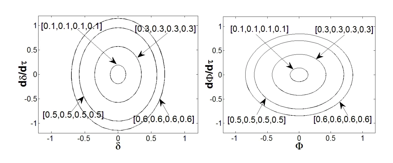
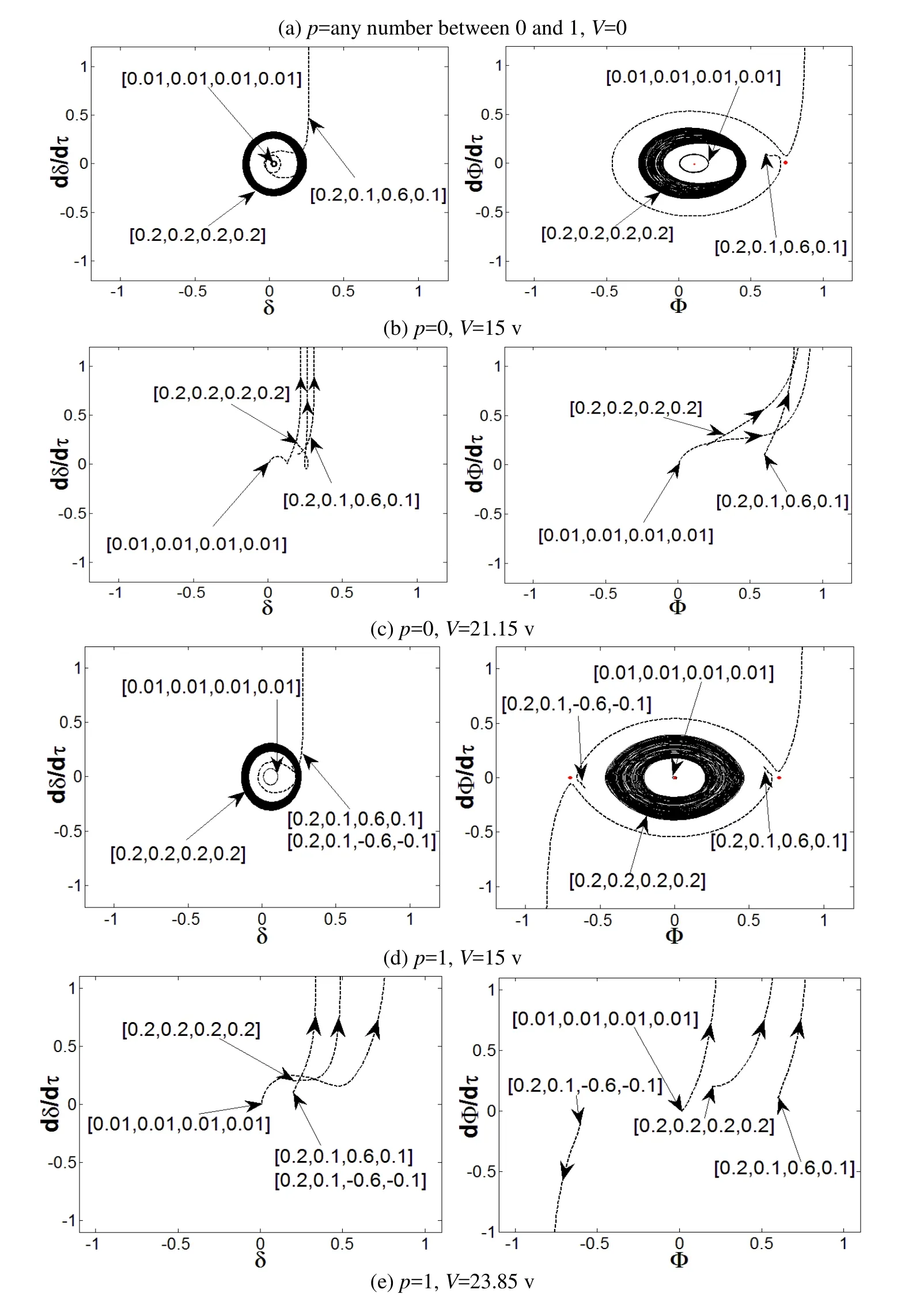
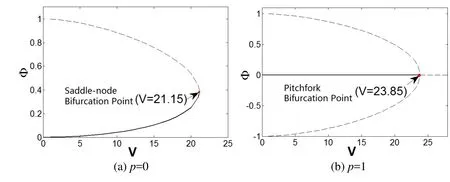
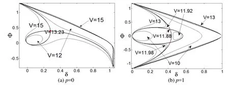
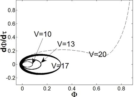
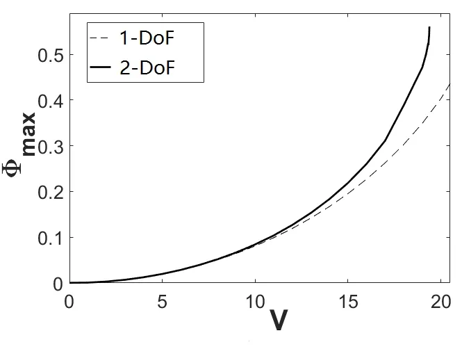
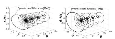
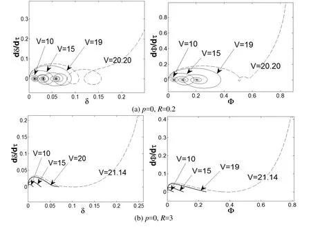
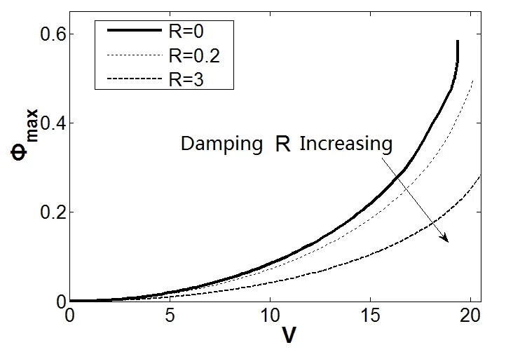
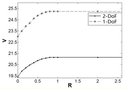
The x1vs. x3relationship curves obtained from solving Eqs. 22(a) and 22(b) are shown in Figs. 2(a) and 2(b), respectively, for the cases of p=0 and p=1, and critical voltage V=10 v. When p=0, V=21.15 v, there is a unique intersection point between curve 1 and curve 2,and the static pull-in occurs, as shown in Fig. 2(a). When p=1, V=23.85 v, there is a unique intersection point between curve 1 and curve 2, and the static pull-in occurs, as shown in Fig. 2(b). Similarly, when the voltage ratio falls in between, i.e. 0 Figure 2: The static pull-in of the 2-DoF micromirror system by the Hamiltonian method In Eq. (18), there are four state variables in the 2-DoF system, namely the two output degrees of freedom and their derivatives, which together constitute a four-dimensional(4D) phase space. In the dynamic phase space built for the system at different driving voltages, the respective projections of the phase diagram onto the (x2, x1) plane and (x4, x3)plane can be used to study both the dynamic behavior and the static characteristics of the system, rather than using the 4D trajectory that is impossible to visualize and hard to analyze. In a nutshell, the phase plane made of the vertical displacement (state variable x1)and x1’s derivative (state variable x2) and the phase plane made of the torsion angle (state variable x3) and x3’s derivative (state variable x4) can be interpreted as two windows to help observe the 4D phase trajectory. After making the damping coefficient in Eq. (18) equal to zero and setting the state variables [x1, x2, x3, x4] with different initial values, for different p and V values, the phase trajectories of the system’s state variables can be obtained using the fourth order Runge-Kutta method, and the projected trajectories for each given [x1, x2, x3, x4] are shown in Fig. 3. Note that the changes of the position of the fixed point and the projected trajectories shown in Fig. 3 can be explored to determine if the system is globally stable. It can be seen from Fig. 3(a), when the driving voltage is zero, there is exactly one stable center point in the system, as exhibited on the phase plane of x4=dφ/dτ vs. φ. Figure 3: The projected phase trajectories of the 2-DoF system without damping In the case of p=0, V≠0 and the driving voltage smaller than a critical value of 21.15 v,different from the line-shaped trajectories as predicted by the 1-DoF model, the actual trajectories, according to the proposed 2-DoF model, form a ring shape, as shown in Fig.3(b). The center point in this case is shifted to the right as the driving voltage increases,and there exists a saddle point in the system. When the critical voltage is reached as the case in Fig. 3(c), it is revealed from the phase diagram that the overall instability arises.That is, the saddle point overlaps with the center point and it actually gets disappeared,meaning that the saddle node bifurcation does occur and the critical voltage is indeed the static pull-in voltage. In the case of p=1, shown in Figs. 3(a), 3(d), and 3(e), the center remains at the origin,and the system has two saddle points that are symmetric with respect to that center point.Both points are dragged closer to the center point as the driving voltage increases. By the time when the driving voltage reaches the static pull-in voltage, the three equilibria finally merge into one, and thus, the pitchfork bifurcation occurs and the overall instability phenomenon can be seen from the projections of their phase diagrams. It can also be seen from Fig. 3 that the projected unstable trajectories of the vertical displacement and the angle of rotation appear at the same time. The static characteristics of the 2-DoF system can thus be studied by inspecting the number and positions of the main equilibrium points on the phase diagram of the torsional direction. Figure 4: The static characteristic curve of 2-DoF system The summarized static characteristics are shown in Fig. 4. It becomes quite clear that the static pull-in voltage is equal to the static bifurcation voltage, which is 21.15 v for p=0,and 23.85 v for p=1. These results are consistent with those obtained from the Hamiltonian method. When the voltage ratio falls into the range of 0 Dynamic behavior of a torsional micromirror reflects how the system responds to the driving voltage with a special waveform, like a step function. In this section, the pull-in and bifurcation phenomena of the micromirror system driven by the step voltage are analyzed based on 2-DoF model governed by Eq. (18) for two distinct scenarios: one with damping and one without. The dynamic pull-in condition of the undamped 2-DoF micromirror system can always be obtained through the Hamiltonian method given in Eq. (19). The energy constraints of the system denoted as H0can be set as given in Eq. (23) [Elata and Bamberger (2006)]. Since this is an undamped system, energy shall be conserved. That is, Let the state variables x2and x4in Eq. (24) assume the value of zero. That is, both the kinetic energy of the vertical direction and the kinetic energy of the angular direction are equal to zero, which brings up the surface equation of V (x1, x3) as expressed in Eq. (25). The contour on the surface of V (x1, x3) is projected onto the plane (x1, x3), as shown in Fig. 5. The cases of p=0 and p=1 are plotted in Figs. 5(a) and 5(b), respectively. Fig. 5(a) shows that the ideal dynamic bifurcation voltage, for the case of p=0, is 13.23 v.When p = 0 and V (x1, x3) is less than the ideal dynamic bifurcation voltage, the trajectory on the displacement plane (x1, x3) defined by Eq. (25) is separated into two closed regions,which correspond to the stable and unstable equilibrium situations, respectively. The two regions are drawn closer to each other as the driving voltage increases, and they overlap at the unstable equilibrium when the ideal dynamic bifurcation voltage is reached. When the voltage is further increased to surpass the ideal dynamic bifurcation voltage, the two regions actually merge into one single region, and there exists an open path that connects the stable and unstable regions. The contour of the case of p≠0 is similar to that of p=0, as shown in Fig. 5(b), where the ideal dynamic bifurcation voltage is 11.88 v for the case of p=1. The actual movement of the micromirror is different from that of the ideal situation, as shown in Fig. 5, because there exists a nonlinear coupling between state variables x3and x1. Such nonlinear coupling causes an unconstrained phase difference between the torsion movement and the vertical movement. As so, the kinetic energy of the vertical direction and the kinetic energy of the angular direction cannot be zero at the same time, which is different from the undamped situation discussed previously through Eq. (25). Even if the micromirror acquires the same amount of input energy, as shown in Fig. 5, its area enclosed by the actual moving trajectory is smaller than the area enclosed by the ideal trajectory. That is, the actual dynamic pull-in voltage should be greater than the ideal dynamic bifurcation voltage, as indicated in Fig. 5. Figure 5: Ideal dynamic bifurcation characteristics of the undamped 2-DoF system In order to find the actual dynamic pull-in voltage of the undamped 2-DoF micromirror system, one can increment the driving voltage at a step size of 0.01 v, beginning from 0 v and setting the initial state to be [0, 0, 0, 0], after which the trajectory projections for voltage are obtained. Some projected phase trajectories are shown in Fig. 6. As the driving voltage increases, radius of the circle formed by the projected phase trajectory increases as well, and an unstable trajectory appears when the voltage exceeds the pull-in voltage V (x1, x3)=20 v, as shown in Fig. 6. Figure 6: Projected dynamic phase trajectories of zero damping 2-DoF system The dynamic pull-in voltages obtained from the numerical simulation of the 2-DoF system with no damping at p=0 and p=1 are 19.39 v and 22.99 v, respectively, which are larger than their respective ideal dynamic bifurcation voltages of 13.23 v and 11.88 v. In Fig. 7, the dynamic characteristics of the system, for the case of p=0 and voltage swing of 0 v to 20 v, are plotted together in the same figure. One can see that when the driving voltage is larger than 10 v, the difference between the 2-DOF model and the 1-DOF model becomes quite noticeable. These results as plotted in Fig. 7 are in good agreement with those obtained from solving the deferential equations in time domain [Zhao, Chen,Huang et al. (2005)]. Similar observation can be also be made for the cases when p is not equal to zero. These differences clearly indicate that torsion-bending coupling effect should not be omitted from the stability analysis of torsional micromirror system. Figure 7: The comparison of dynamic characteristic curves between 2-DoF and 1-DoF system In addition to the driving voltage, the damping coefficients of the system can also impact the system pull-in. Figure 8: The dynamic Hopf bifurcation of the 2-DoF system with the damping factor R assuming V=0 and initial state of [0.1, 0.2, 0.2, 0.7]. As shown in Fig. 8, with both the driving voltage and the initial state are fixed, say V=0 and the initial state of [0.1, 0.2, 0.2, 0.7], when the damping coefficient sweeps over a wide range, say R0=R1=R=0.4, down to R0=R1=R=0, there is a drastic shape change of the projected trajectories, going from a spiral shape with a focus point, for the case of R=0.4, to a limit cycle, for the case of R=0. In the latter case, a Hopf bifurcation actually occurs. The analysis method of the actual dynamic pull-in voltage of damped 2-DoF system is similar to that of the undamped system. As the driving voltage sweeps a step size of 0.01v along with the initial state of [0, 0, 0, 0], the trajectory of 2-DoF is calculated and projected onto both the torsional direction and the vertical direction. A few phase trajectory projection curves for a few damping coefficients, R=0.2, 3, are shown in Fig. 9.When the equivalent damping coefficient R≠0 and the voltage is smaller than the critical voltage, the trajectory shows the corresponding focus point. But when the critical voltage is reached, there exists an unstable trajectory, which indicates the occurrence of pull-in. Figure 9: The projection of phase trajectories of 2-DoF system with different damping Applying different driving voltages to the 2-DoF system with R=0, 0.2, 3, the pull-in angle and the pull-in voltage for 2-DoF system with different damping coefficients are plotted in Fig. 10. One can see that dynamic pull-in voltage increases along with the increase of the damping coefficient. In another word, if the driving voltage remains fixed,the maximum deflection angle is smaller for higher damping coefficient, indicating that damping tends to make the system more stable. Fig. 11 plots the dynamic pull-in voltages across a range of damping coefficients, as obtained from the 2-DoF micromirror system and the 1-DoF. One can see that the dynamic pull-in voltage predicted by the 2-DoF model is considerably lower than that is predicted by the 1-DoF model for the same damping coefficient and p=0. Figure 10: Pull-in angle vs. pull-in voltage for 2-DoF system at damping R=0, 0.2, 3 Figure 11: The dynamic pull-in voltages vs. different the damping factors for 2-DoF and 1-DoF systems In this paper, two degrees of freedom dynamic model was constructed for an electrostatically driven torsional micromirror system with double bottom plates and two voltage sources. Based on the dimensionless phase space model equation thus constructed,the pull-in and bifurcation phenomena were analyzed using the Hamiltonian method and numerical method. The following conclusions are drawn: 1. Due to the torsion-bending coupling effect, when the driving voltage is smaller than a critical voltage but larger than zero, the 2-DoF system shows ring-shaped projected trajectories whereas the line-shaped trajectory is predicted by the 1-DoF system. In addition, saddle node bifurcation, pitchfork bifurcation and Hopf bifurcation can all be predicted by the 2-DoF model for MEMS torsional micromirror. The pull-in conditions can be readily identified by examining these bifurcation points. 2. Static bifurcation and static pull-in voltage are essentially the same, and they have higher value than the dynamic pull-in voltage. The static pull-in voltage is nearly the same as the dynamic voltage when the voltage ratio is close to 1. The dynamic pullin voltage, on the other hand, falls between the ideal dynamic bifurcation voltage and the static bifurcation voltage. The driving voltage applied to the bottom gate must be higher than the ideal dynamic bifurcation voltage for a dynamic pull-in to occur. In addition, dynamic pull-in voltage varies with the voltage ratio. 3. Even with the same initial state, the pull-in voltage of the damped system is always lower than that of the undamped system; the pull-in voltage increases with damping.When the same driving voltage is applied, maximum deflection angle drops as damping increases. At the damping coefficient R=0, the system shows a dynamic Hopf bifurcation. 4. Pull-in voltage predicted by the 2-DoF system is considerably lower than that by the 1-DoF, clearly indicating that for accurate stability analysis of a torsional micromirror, the torsion- bending coupling effect should not be ignored. Acknowledgement:This work is supported by the National Natural Science Foundation of China (Project 61368004), the Fund of National High-level Overseas Talent Returning([2011]481), and a scholarship from China Scholarship Council (No. 201703000001). Azizi, S.; Ghazavi, M.; Khadem, S. E.; Rezazadeh, G.; Cetinkaya, C.(2013):Application of piezoelectric actuation to regularize the chaotic response of an electrostatically actuated micro-beam. Nonlinear Dynamics, vol. 73, pp. 853-867. Elata, D.; Bamberger, H.(2006): On the dynamic pull-in of electrostatic actuators with multiple degrees of freedom and multiple voltage sources. Journal of Microelectromechanical Systems, vol. 15, no. 1, pp. 131-140. Huang, J.; Liu, A.(2004): An approach to the coupling effect between torsion and bending for electrostatic torsional micromirrors. Sensors & Actuators A Physical, vol.115, no. 1, pp. 159-167. Koay, L. K.; Rahim, N. A. A.(2016): Reviews: Torsional spring mechanism resonant scanner’s technology. Journal of Mechanical Science and Technology, vol. 30, no. 4, pp.1781-1798 Li, L.; Zhang, Q. C.(2016): Nonlinear dynamic analysis of electrically actuated viscoelastic bistable microbeam system. Nonlinear Dynamics, vol. 87, no. 1, pp. 587-604 Li, Q.; Xi, J.; Hua, C.(2011): Bifurcations of a micro-electromechanical nonlinear coupling system. Communications in Nonlinear Science & Numerical Simulation, vol. 16,no. 2, pp. 769-775. Li, Y.; Duan, W.; Ma, S.; Li, P.(2014): Bifurcation of a microelectro mechanical nonlinear coupling system with delay feedback. Journal of Applied Mathematics, vol.2014, pp. 1-6. Pelesko, J. A.(2002): Mathematical modeling of electrostatic MEMS with tailored dielectric properties. SIAM Journal on Applied Mathematics, vol. 62, no. 3, pp. 888-908. Pratiher, B.(2014): Stability and bifurcation analysis of an electrostatically controlled highly deformable microcantilever based resonator. Nonlinear Dynamics, vol. 78, no. 3,pp. 1781-1800. Shang, H.; Song, S.; Wen, Y.(2016): Controlling pull-in instability of a typical electrostatically actuated microsensor with time-delay position feedback. Journal of Vibration and Shock, vol. 35, no. 4, pp. 81-86. (in Chinese) Taghizadeh, M.; Mobki, H.(2014): Bifurcation analysis of torsional micromirror actuated by electrostatic forces. Archives of Mechanics, vol. 66, no. 2, pp. 95-111. Wetsel, G. C.; Strozewski, K. J.(1993): Dynamical model of microscale electromechanical spatial light modulator. Journal of Applied Physics, vol. 73, no. 11, pp. 7120-7124. Zhang, W. M.; Yan, H.; Peng, Z. K.; Meng, G.(2014): Electrostatic pull-in instability in MEMS/NEMS: a review. Sensors & Actuators A Physical, vol. 214, no. 4, pp. 187-218. Zhang, W.; Meng, G.; Chen, D.(2007): Stability, nonlinearity and reliability of electrostatically actuated MEMS devices. Sensors, vol. 7, pp. 760-796. Zhang, X. M.; Chau, F. S.; Quan, C.; Lam, Y. L.; Liu, A. Q.(2001): A study of the static characteristics of a torsional micromirror. Sensors & Actuators A Physical, vol. 90,pp. 73-81. Zhao, J. P.; Chen, H. L.; Huang, J. M.; Liu, A. Q.(2005): A study of dynamic characteristics and simulation of MEMS torsional micro mirrors. Sensors & Actuators A Physical, vol. 120, no. 1, pp. 199-210.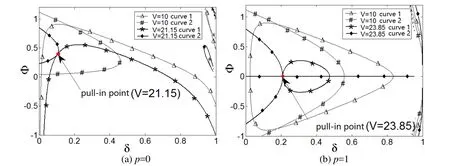
3.2 Numerical solution in phase space
4 Dynamic pull-in and bifurcation
4.1 System without damping


4.2 System with damping
5 Conclusion
 Computer Modeling In Engineering&Sciences2018年3期
