Motion Analysis of Trunk Using Simplified Human Model in Sagittal Plane
,
1.Division of Mechanical Engineering,Graduate School of Science and Technology,Sophia University,Tokyo,Japan;
2.Department of Engineering and Applied Sciences,Sophia University,Tokyo,Japan
0 Introduction
Small vehicles,called the personal mobility vehicles designed to transport a single occupant,have been actively developed recently.Such vehicles are ecological,user friendly,and can provide comfortable transportation over short to middle distances.However,the posture of a driver would be different from conventional vehicles one.Furthermore,driving posture,and even drivers themselves diversify in Japan′s aging society.In particular,characteristics of the elders as Japanese society becomes older[1].In addition,it is necessary for the driver′s physical characteristics to be considered during design and development,because the motion of the human would influence a light vehicle.One method for investigating the motion of a human riding a vehicle is through experiments.For example,experiments measuring vibration transfer from the seat to the occupant when driving[2],and vibration seat testing using vibration exciters has been performed in the past[3].However,experiments involving actual vehicles are expensive and there are safety concerns when human test subjects are used.Therefore,as a method for evaluating vehicle occupant motion,numerical simulations are suggested.We proposed an integrated system composed of a combination of generalized software and original code that creates a motion generation model capable of evaluating the motion resulting from a vehicle-to-human coupling[4-5].The advantage of this method is that body motion can be simulated and evaluated via numerical simulations using computer only.This reduces development costs,improves safety,and provides an environment that makes it easy to change human body parameters within the program.Thus,development of numerical simulation models for human motion is important,because such models make it possible to perform integrated development of personal mobility vehicles in the future.However,when a full-body model of human is simulated,multiple degrees of freedom are involved and it becomes difficult to grasp various body motion phenomena using the motion control model.As a result,the influences of body model movements(set via various parameters)are obscure,and control of the motion model becomes difficult.Therefore,the human body is modeled as a simplified trunk from the point of view of scalable multibody dynamics in order to gain knowledge on human body motion control.A simplified human-body dynamics model in the frontal plane that can identify characteristics of motion control based on actual human responses has previously been proposed[6].The parameters for this human motion control were identified based on the results of experiments and simulations.The motion characteristics of an individual human in the frontal plane were then considered based on the obtained parameters.Here,the parameters for the sagittal plane are identified from the results of experiments and simulations,and are then used to simulate human motion.
1 Human-Body Dynamics Model
1.1 Overview of motion control
The proposed human-body dynamics model consists of an internal and external model[7].The internal model consisting of inverse and forward models generates commands to control body motion,while the external model simulates actual body motion.This process is shown as a block diagram in Fig.1,while a conceptual diagram for the model is shown in Fig.2.First,in the internal model,the target position and representative position of body motion is set to generate body motion.Therefore,complex body motion is defined as the transfer of a representative point from its initial position to its target position.In addition,body motion is generated by physical forces which move the point closer to the target position.Each joint torque using the inverse model by the generated motion becomes a body motion command.However,it is not easy to express body motion using the torque calculated using the inverse model[8].Therefore,this torque is adjusted by using the forward model.Then,the body motion is generated by the adjusted torque in the human body model.

Fig.1 Block diagram of body motion control

Fig.2 Motion due to applied force
1.2 Human-body model
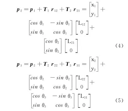
Fig.3shows an analytical human-body model.The model is placed in a coordinate system that is movable on a fixed spatial coordinate system.Vehicle motion and human motion are described in the same coordinate system.This model is a three-link rigid model consisting of a head,one spine,and one pelvis.It is formulated using multibody dynamics and analyzed using an augmented formulation.Li1are the distances from the bottom of each rigid body part to the center-of-gravity (COG),andLi2are the distances from the COG to the top of each rigid body(i=1,2,3).
The generalized coordinates are given by

wherexi,yiandθiare the coordinates of the COG and an angle.The virtual work is expressed as

where Mis the mass matrix.Mass and inertia moment of each body are estimated from weight and height[9].Qais a vector composed by external force and passive joint resistance.


whereNx,Nyare the contact forces between human body and seat,Nθthe moment by seat reaction force,andTθj(j=2,3)the non-linear passive resistance.piare the position vectors for the COG of the rigid bodies.Using rijwhich are position vectors in the fixed coordinate system,one gets

where Tiis the transformation matrix.

Fig.3 Analytical model
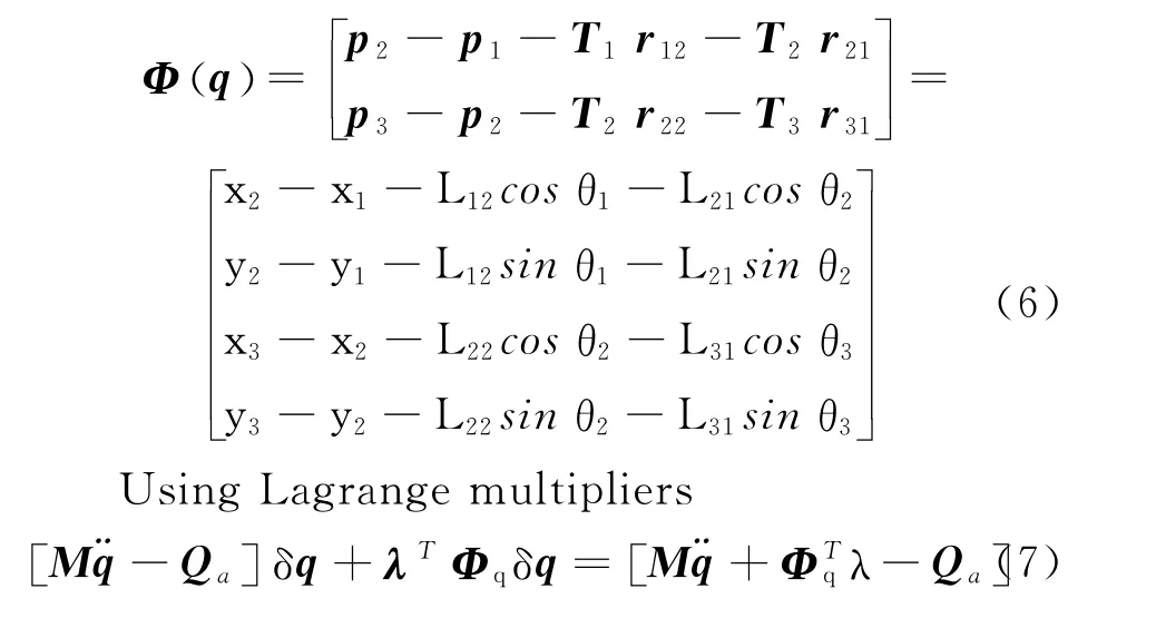
Then,the constraint on the system is


whereΦqis the Jacobian matrix.Differentiating Eq.(6)twice with respect to time

Using Eqs.(7,9),differential algebraic equations(DAE)can be obtained as

1.3 Contact force
Basically speaking,any contact between the body and seat is considered to be a surface contact.In addition,the skin tissue of the body and the seat exhibit nonlinear viscoelasticity.However,considering these characteristics would require expensive calculation costs and numerous properties.Therefore,to simplify contact force,contact points are set on the body.The definition of the contact force is shown in Fig.4,where the definition of the tangential contact force of seat surface is shown in Fig.4(a),and that of the normal direction contact force of the seat surface is shown in 4(b).To reproduce simplified human motion,elasticity and viscosity elements are assumed in the model.In addition,the tangential contact force is allowed to reaction force depending on relative displacement and velocity in contact position.
The reaction forces from the seat are

whereNx,Nyare the contact forces in the tangential and normal directions;ksx,ksythe elastic constants;csx,csythe viscosity constants,ethe exponent for elasticity,Rthe center of the seat,x0the median of the contact point,andy0the distance between the contact point and the upper surface of seat[8].As shown in Fig.4,two contact points are defined on each side of the model bottom.This allows the model to move while main-taining posture via two contact points.

Fig.4 Contact model
1.4 Torque generation via inverse model
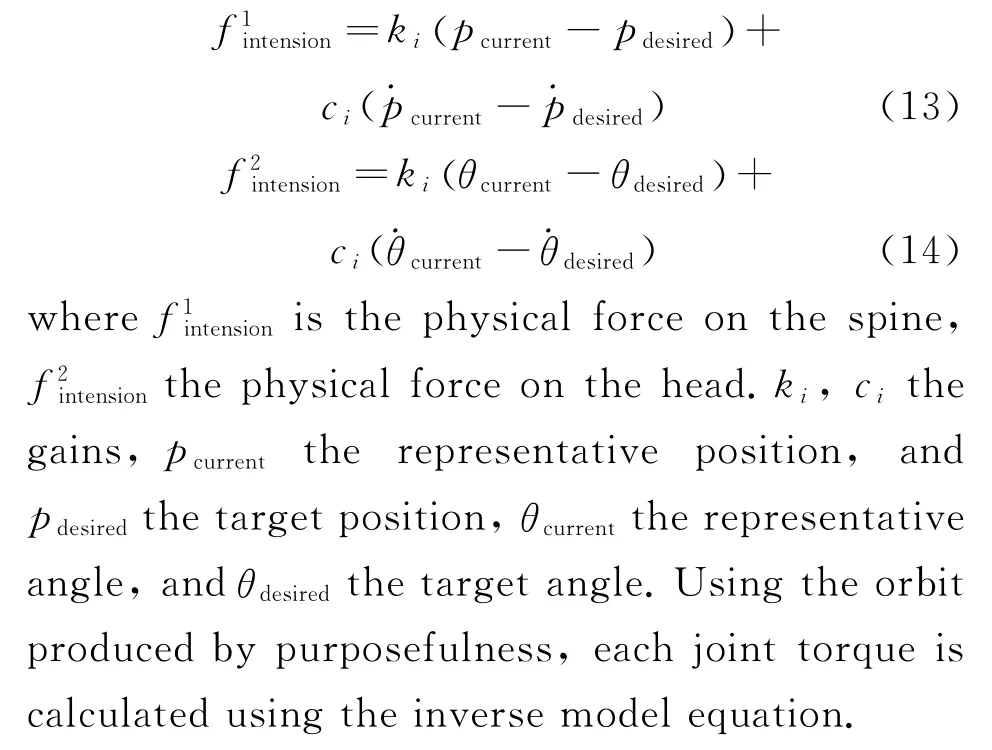
It is considered that body motion is generated by torque based on the planned trajectory of motion using the inverse model[10].First,in this human-body model,a trajectory is generated by a force that moves the representative point closer to the target position.It is difficult to imagine that a human being would be conscious of the torque of each joint.Accordingly,the purposefulness required to move a body point and angle to the target position and angle is considered to be a physical force and is defined as follows.In the case of the spine,the upper end of the spine is moved close to the target point.In case of head,the representative angle is moved close to the target angle.

1.5 Adjustment of joint torque using forward model
It might be expected that the generation of motion occurs according to trajectory by the inverse model.However,the human body does not always move according to the planned trajectory because of relative delays and other factors[11].Accordingly,to express the actual motion of a biological body,a forward model that enables anticipatory motion control is added.This forward model framed gradient system defines an equilibrium target position by adding the interactions of each joint torque,and a potential function is defined by the target position and representative position differences over a short period of time later.This potential function is called the performance index potential.In this model,the joint torque that moves the representative position to the target position in the shortest period of time is calculated because the time gain is conformed as the direction of steepest potential gradient in the gradient method.This enables the posture to be maintained.In addition,to follow the motion trajectory,the torque is adjusted using the following equation in such a way as to accord as much as possible value in joint torque value calculated by the inverse model.

whereτis the time constant,K3the learning coefficient,vthe state variable equivalent of the joint torque,Uforwardthe performance index potential,andnthe joint torque calculated by the inverse model.From Eq.(15),it can be seen that the velocity variation of the torque decreases asτincreases.This means that reaction speed variations can be expressed by the time constant.
2 Experiment on Acceleration of Vehicle
An overview of the experimental device is shown in Fig.5.The experimental device consists of a chassis,a folding chair,a rubber belt to add tension,a motion capture system,and twelve motion capture cameras(Optitrack Flex3:Optical type,Sample rate:100Hz).This experimental device measures the motion of a human body using a motion capture system when a horizontal acceleration is applied to the seat by a rubber belt.The belt is pulled by the winch.The vehicle is fixed in place and then released.An input acceleration is adjusted based on the length of the rubber belt.The seat used in the experiment is a folding chair fixed by bolts to a chassis.By attaching a marker to experimental subjects and shooting with a motion capture camera,data on body behavior was obtained.

Fig.5 Overview of experimental device
2.1 Experimental conditions
The experimental subjects were two adult males,as shown in Table 1.The influence on body behavior by the different accelerations was investigated in this experiment.Therefore,two acceleration conditions were simulated by changing the rubber belt length.Here,experiments were conducted at speeds of 1.2m/s2and 0.8m/s2.However,for the same rubber belt length,the acceleration will be different depending on the weight of the experimental subject.Hence,the reference mass was set as 75kg by using a weight and a constant acceleration was simulated.The experimental conditions are shown in Table 2.The experimental subject closed their eyes,relaxed,extended their spines to the target posture,and maintained their posture.

Table 1 Experimental subjects

Table 2 Experimental conditions
2.2 Method of parameter identification
The model has two features.One is that function derivation is difficult,because body motion is described by complex nonlinear equations.Another is that a strict optimal solution is not needed,because there is some individual tolerance level to differences in body motion.Therefore,in order to search for parameters,agenetic algorithm (GA),as an optimization technique,was used.The evaluation function used for optimization was set so that the fitness was maximized when the difference between the experimental and analytical results were minimized.
The evaluation function is

2.3 Results of identification
Numerical simulation of the human-body model is performed using the parameters obtained by the GA and compared with the experimental results.The control parameters for each experimental subject are shown in Tables 3,4.A comparison of the simulation results of the body part for different conditions and the experimental results are shown in Fig.6.As an example,the identification result of Trial 1with Condition 1(Subject A)is shown.From Fig.6,it can be seen that the simulation results for the spine and the head in Condition 1for Subject A coincide with the experimental results.Also,in both cases,the pelvis inclines forward due to the acceleration and then returns to the target posture.Similar results were obtained for other trials and also for Subject B.
From the above results,it was found that by using this human-body model,the characteristic body behavior and reaction to acceleration in the direction of travel of the vehicle can be matched.Moreover,in each analysis,the difference for each experimental condition can be reproduced,and the usefulness of this human-body model can be confirmed.

Table 3 Simulation parameters(Subject A)

Table 4 Simulation parameters(Subject B)

Fig.6 Time history of top of each part(Subject A)
3 Comparison Between Body Motion and Simulation Parameters
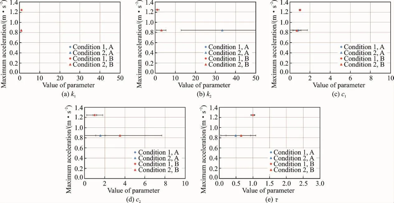
Subsequently,the relation between the identified control parameters and human body behavior is described.The relationships between vehicle acceleration and control parameters for Subjects A and B are shown in Fig.7.The error bars in the Fig.7represent the standard deviation for each condition,and this distribution obtained by dividing the parameter obtained under each condition by the average value for Condition 1.
From Tables 3,4,it can be seen thatk1andc1are larger thank2andc2in all trials.The torque required to maintain the position of the trunk is larger than that required to maintain the position of the head.This result is understandable considering the mass ratio of the head and trunk.Thus,maintaining the posture of the spine is prioritized when a human is subject to vertical acceleration.This tendency is similar in the case of horizontal acceleration[6].The time constant varies in Condition 2.This does not correspond to the case of horizontal acceleration.This is because visual feedback influences the motion of a human body.
It can be seen that the standard deviation also changes with acceleration.From Fig.7,the standard deviation ofc1for Subject A increases with
4 Conclusions

Fig.7 Relationships between maximum acceleration and individual parameters
The motion control of the human head and decreasing acceleration.This tendency is also obtained for Subject B.This relationship between acceleration and the standard deviation is also shown ink2andc2.As the acceleration decreases,the standard deviation ofk2for Subject A increases,but the standard deviation ofc2for Subject A decreases.On the other hand,there is a difference in the tendency of the standard deviation ofc2for Subject B.These differences are due to the change in the path of posture maintenance described above.These results suggest that many paths for maintaining posture during acceleration are available.
As described above,in each individual,there are parameters that do not change greatly even if conditions change,and parameters that greatly change depending on conditions.Especially under low acceleration conditions,it was shown that the standard deviation of head motion was large,and it turned out that diverse human path strategy existed.Using this model,it is shown that the possibility to investigate the characteristics of individual movement.In the future,more detailed analysis is planned by increasing the number of subjects and conditions.
trunk is investigated,and a simplified human model is proposed,which can identify the characteristics of motion control based on actual human responses.Using the human-body dynamics model,we considered the relationships between the input conditions and each parameter of the model.We designed a simplified identification experiment to focus on maintaining the posture of the human body during acceleration and considered human motion.We identified the parameters of the human motion model based on the experimental results.The numerical simulation results using the identified parameter values concurs with the experimental results,and human body behavior can be simulated using the model.Moreover,the relation between the identified control parameters and human body behavior was shown.In each individual,there are parameters that do not change significantly even if conditions vary,and parameters that greatly change depending on conditions.The results suggested that many paths for maintaining posture during acceleration were available.Using the proposed numerical model provides a possibility to investigate the control characteris-tics of individual movement.In the future,more detailed analysis is planned by increasing the number of subjects and conditions.Moreover,we consider other method of purposefulness.
[1] MOTOKI S,TAKASHI H,NOBUTAKA U,et al.Study on driving characteristics of older drivers and its relevance factor[J].Transactions of the Society of Mechanical Engineers Series C,2005,71(709):124-131.
[2] YI Q,MICHAEL J G.Transmission of roll,pitch and yaw vibration to the backrest of a seat supported on a non-rigid car floor[J].Journal of Sound Vibration,2005,288(4/5):1197-1222.
[3] GEN T,TAKUYA Y,KOUHEI S.Dynamics and modelling of human body exposed to multidirectional excitation.Dynamic Characteristics of Human Body Determined by Triaxial Vibration Test[J].Transactions of the Society of Mechanical Engineers Series C,1998,64(617):266-272.(in Japanese)
[4] SHOICHIRO T,RYUTARO U,KAZUNORI H.Development of postural assessment system based on biomechanics simulation system integration[J].Journal of Automotive Engineering,2012,43(6):1353-1357.
[5] SHOICHIRO T,AKIHIRO T,TATSUO U,et al.Development of a simplified human body dynamics model for motion control on a vehicle[J].Bulletin of JSME Mechanical Engineering Journal,2017,4(1):16-00455.
[6] TATSUO U,SHOICHIRO T,FUMIYA T,et al.Estimation of human motion using a simplified human-body dynamics model[J].Bulletin of JSME Mechanical Engineering Journal,2017,4(5):16-00704.
[7] KOUJI I.Physical intellect system theory[M].[S.l.]:Kyoritsu-Syuppan,2005.
[8] SEPTIMIU E S.On the emulation of stiff walls and static friction with a magnetically levitated input-output device[J].Transactions of the ASME,Journal of Dynamic Systems Measurement and Control,1997,119(1):127-132.
[9] ZATSIORSKY V,SELUYANOV V.The mass and inertia characteristics of the main segments of the human body [M].[S.l.]:Biomechanics VIII-B,1983:1152-1159.
[10]TIE W,GORAN S D.Learning the dynamics of reaching movements results in the modification of arm impedance and long-latency perturbation responses[J].Biological Cybernetics,2001,85:437-448.
[11]NAOKI T,MANABU G,KOJI I.Inaccuracy of internal models in force fields and complementary use of impedance control[J].Transactions of the Society of Instrument and Control Engineers,2008,44(11):896-904.
 Transactions of Nanjing University of Aeronautics and Astronautics2018年1期
- Transactions of Nanjing University of Aeronautics and Astronautics的其它文章
- Parametric Study of Low Frequency Broadband Rectilinear-to-Rotary Vibrational Energy Harvesting
- Countermeasure Against Regenerative and Forced Chatter of Flexible Workpieces in Milling Processs Using Bi-directional Excitation
- Experiment on a Semi-Active In-Car Crib with Joint Application of Regular and Inverted Pendulum Mechanisms Using Scale Model
- Variational Mode Decomposition for Rotating Machinery Condition Monitoring Using Vibration Signals
- Rotational Motions Excited by Vertical Harmonic Motions
- Improved Methods for In-situ Measurement Railway Noise Barrier Insertion Loss
