Multi-camera calibration method based on minimizing the difference of reprojection error vectors
HUO Ju,LI Yunhui,and YANG Ming,*
1.School of Electrical Engineering,Harbin Institute of Technology,Harbin 150001,China;
2.Control and Simulation Center,Harbin Institute of Technology,Harbin 150080,China
Abstract:In order to achieve a high precision in three-dimensional(3D)multi-camera measurement system,an efficient multi-camera calibration method is proposed.A stitching method of large scale calibration targets is deduced,and a fundamental of multi-camera calibration based on the large scale calibration target is provided.To avoid the shortcomings of the method,the vector differences of reprojection error with the presence of the constraint condition of the constant rigid body transformation is modelled,and minimized by the Levenberg-Marquardt(LM)method.Results of the simulation and observation data calibration experiment show that the accuracy of the system calibrated by the proposed method reaches 2 mm when measuring distance section of 20 000 mm and scale section of 7 000 mm×7 000 mm.Consequently,the proposed method of multi-camera calibration performs better than the fundamental in stability.This technique offers a more uniform error distribution for measuring large scale space.
Keywords:vision measurement,multi-camera calibration, field stitching,vector error.
1.Introduction
With the rapid development of industrial manufacturing technology[1-5],the demand for a wide range of visual measurement technology is also growing[6,7].Raising the camera’s field-of-view(FOV)will lead to a great challenge to economic applicability[8,9].Therefore,an alternative method is the multiple camera’s FOV splicing,which can obtain a large FOV[10,11].For high precision calibration of multiple cameras,the presence problem of large size and high precision calibration target manufacturing is difficult to solve, and the parameters of camera, such as intrinsic parameters,external parameters, field angle,object distance and calibration point layout are hard to keep consistent[12,13].Therefore,each camera parameter calibrated by the traditional calibration method is a set of local optimal parameters,which are relative to the range of the FOV of itself[14-17].When using local optimum camera calibration results for three-dimensional(3D)measurement,a same measurement task(such as a gauging rod length test)will be inconsistent measurement results.
In order to solve the problem of multi-camera calibration,Kitahara et al.directly measured the 3D coordinates of calibration points on the calibration target with the aid of laser track and other 3D measuring instruments.Then according to the features that all coordinates value is within a same world coordinate system,multiple camera of global calibration is achieved.This method is easy to operate and has fewer steps,but a high-precision large-scale calibration target is still necessary.Therefore,its global calibration accuracy varies with the increasing measurement range and becomes worse[18,19].Zhang et al.found that the points of the same laser beam on the same line achieve the global camera calibration through the constraint condition by the laser medium.The method does not require expensive 3D measurement equipment,but needs multiple rotations in the laser beam under camera’s FOV. The operation of the method is complicated and the global calibration accuracy is relevant with the precision of laser projector spot extract[20,21].Kumar et al.proposed a calibration method combined with mirror and plane targets.Firstly,the intrinsic and external parameter of the mirrored camera was calibrated using the standard calibration method,and then the external parameter of real cameras was estimated using the constant constraint relationship between the real camera and the mirrored camera,and finally the calibration result of multi-camera with non-overlapping FOV was achieved.The method is flexible and easy to operate,and the constraint relationship between the cameras is a linear equation.No additional nonlinear equation needs to be solved,but the result of the camera calibration is easy to be affected by the mirror machining accuracy and the positional relationship between the mirror and the camera[22,23].Frank Pagel et al.proposed a calibration algorithm of non-overlapping multi-camera based on a mobile platform.It first calibrated the intrinsic parameter of the camera,and then set the calibration template,and finally stepped the calculated extrinsic parameter to achieve a global multiple camera calibration task on the car.The template configuration of this method is very simple and with strong flexibility.However,the accuracy of the calibration results was affected by template motion platform vibration,deformation and other factors[24,25].In summary,for the problem of multi-camera calibration,although there are many methods proposed and used,the global calibration method still satisfies not only simple calibration operation,but also high calibration accuracy.
Therefore,this paper presents a method for multicamera calibration based on minimizing the difference of the reprojection error vector of the corresponding calibration points in the FOV.First of all,a number of calibration features points are symmetrically arranged in the FOV of the camera,and then the 3D coordinates of all calibration points are measured by the 3D measuring instrument,and with the multi-camera calibration method based on large scale calibration targets, the initial parameters of each camera are carried out.Finally,the sum of the vector differences of reprojection error is used to establish the objective function,and the parameters of camera calibration are solved by the optimization algorithm.
2.Basic theory
2.1 Mathematic model of camera
The perspective projection model is a widely used camera imaging model in computer vision[26,27],as shown in Fig.1,a camera is modeled by the usual pinhole,the relationship between a 3D point P(xw,yw,zw)and its image projection P(u,v)is given by

where s is a nonzero scale factor,fx=f/dx,fy=f/dy,dx,dy,cx,cyare the intrinsic parameters of the camera,and f is the camera focal length,and dxis the center to center distance between adjacent sensor elements in the X(scan line)line,and dyis the center to center distance between adjacent charge-coupled device(CCD)sensors in the Y direction,and(cx,cy)is the principal point.R and t,called the extrinsic parameters,are the rotation matrix and the translation vector from world coordinate frame to camera coordinate frame,respectively.Note that the skew of two images is not considered in this article.
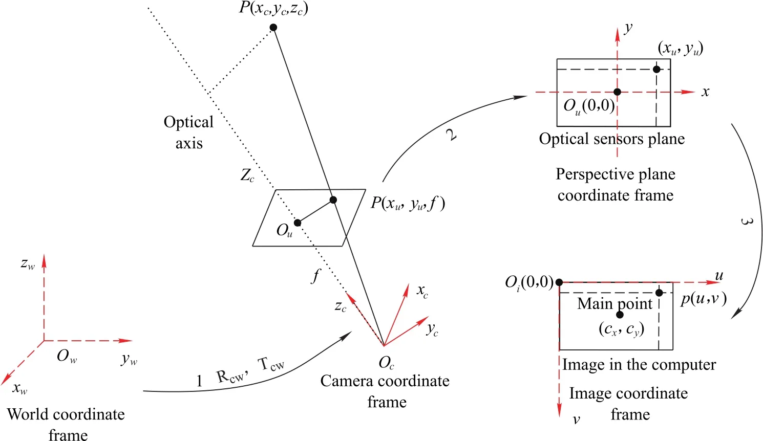
Fig.1 The mathematic model of camera
Due to processing,installation and other reasons,the camera lens is often distorted,space projection does not strictly comply with the perspective projection imaging model.Camera lens distortion can be divided into radial distortion,tangential distortion,centrifugal distortion and thin edge distortion.Radial distortion is usually considered as a major influence on camera imaging.Assume the ideal coordinate is pu(xu,yu)and the actual coordinate is pd(xd,yd),in the image plane of the imaging point of the spatial point P,both have the following relationship:

2.2 Stitching principle of large scale targets
As shown in Fig.2,assume the coordinate of feature point P1is Xw1in the calibration target 1,and Xw2of feature point in target 2 coordinate frame,then the coordinate of this point in the coordinate frame of 3D measurement equipment can be expressed as follows:


Obviously Xt1=Xt2,the coordinate system relationship of two calibration targets is solved by simultaneous equations(3)and(4),it can be expressed as follows:


We can stitch two calibration targets into a whole using(6),as shown in Fig.2,the circle cooperation targets are arranged in the same plane to compose a calibration target.
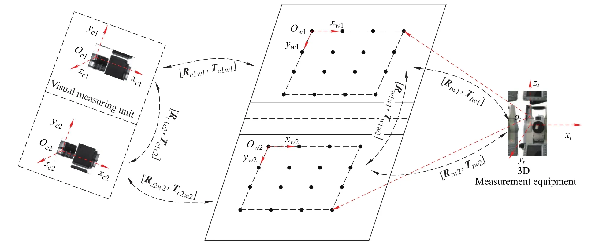
Fig.2 Calibration process of vision measuring unit composed of two cameras
2.3 Multi-camera calibration principle based on large-scale targets
Considering a single camera calibration,(7)can be acquired under the conditions of radial consistency constraint:
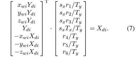
If the world and image coordinates of calibration target feature point are substituted into(7),the values of sxr1/Ty,sxr2/Ty,sxr3/Ty,sxTx1/Ty,r4/Ty,r5/Ty,r6/Tycan be solved by the least square method,and the sx,r1,...,r9,Tx,Tycan be calculated combined with orthogonality of rotation matrix R.
Set the distortion parameters of two cameras k=0,the principal point(u0,v0)is the center coordinate of the computer screen,and the world coordinate of the calibration target feature point is substituted into

where

the initial values of f,Tzare acquired by solving(8).
The cameras parameters Ac1,Rc1w1,Tc1w1,Ac2,Rc2w2,Tc2w2can be obtained by utilizing the above calibration method,combined with calibration point in cameras FOV.
The first calibration target coordinate frame is defined as a world frame,and because the transform relationships R12and T12of calibration targets are constants,it can be calibrated using 3D measurement equipment,so the relationships Rc2w1and Tw1c2between the second camera coordinate frame and the world coordinate frame can be calculated by R12,T12,Rc2w2and Tw2c2.

Because the intrinsic parameter remains unchanged,through the above steps,the large FOV vision measuring unit combined with two cameras could be calibrated.
3.Optimization method for multi-camera calibration
3.1 Problems and solutions of multi-camera calibration principle based on large-scale targets
Through analysis of the previous section of the basic principles of multi-camera calibration,it can be found that there are still three aspects of the problems as follows:
(i)The problem of reprojection error jump change
According to the large size calibration target stitching principle(6),it shows that the stitching accuracy is directly related to R12and T21.The coplanar calibration is

However,R12and T21is related to the accuracy of the 3D measuring device.Due to the accuracy limitation of the 3D measuring device

Therefore,if the stitching target coplanar calibrates the multi-camera,the object side of the reprojection error mean is not equal.When the camera for the moving target parameter measurement is switched,the object-side reverse projection error will change abruptly,so it is necessary to take this factor into account when calibrating the camera.
(ii)The problem of different cameras on the same calibration point reprojection error vector is not equal
For coplanar calibration targets,the formulae of the three coordinates are as follows:

According to the expression of the reprojection error, it is a two-dimensional vector on the target plane, and the one for the same calibration point obtained coordinates varies with different cameras in the direction of XwandYw.As shown in Fig.3,in the corresponding FOV,the situations that the sizes and directions of the reprojection error of the same point use two cameras are greatly different.Therefore,in order to minimize the difference of the reprojection error vector of corresponding calibration point,it is necessary to consider this factor in multi-camera calibration.
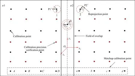
Fig.3 Schematic diagram of camera calibration
(iii)The influence of illumination variation and vibration factor to the camera calibration
When the splicing’s large-size target is used to calibrate the visual measurement unit,the multi-frame image is usua
lly acquired for the least square solution of the parameters to improve the calibration accuracy.
In order to solve the above problems,based on the above analysis of the problem,consider the use of the following three constraints:
(i)The positional relationship between two cameras in the visual measuring unit remains constant,that is,in the n times calibration,the relationship between the results of each calibration should satisfy that the transformation relationship is constant;
(ii)The projection error of projection point in the FOV of each camera is the smallest and=0;
(iii)The difference of the projection error vectors of the calibration points in the corresponding areas of the cameras is the smallest.
According to the above three constraints,the calibration process can be divided into two steps.One is to use the first two constraints to solve the high precision calibration parameters of the two camera parameters,and the third is to optimize the camera parameters to obtain variations of the smaller calibration results between each other.
3.2 Multi-camera high precision calibration under the condition of multi-constraint
According to the first constraint,the relationships between Rc1c2and Tc1c2of two cameras are constants.Utilizing Rc1c2,Tc1c2,Rw1c1and Tw1c1,the calibration parameters Rc2w1,Tw1c2of the camera 2 relative to the world coordinate frame can be calculated as follows.

Therefore,there are fixed constraint

where m and n are arbitrary calibration image pairs of the two cameras in many times calibration,[m-n]represents the extrinsic calibration parameters difference of the mth and the nth images pairs,and normalization maintains number stability.
According to the second constraint,the reprojection error of the calibration target feature point in the target coordinate frame can be calculated as follows:

wherePiis there construction point,h=1,2represent different cameras,Phiis the 3D coordinate of the real point,considering minimizing the reprojection error of the calibration point of two cameras,let the cost function be
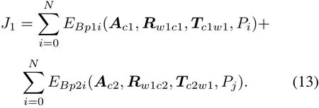
The object function could be expressed as
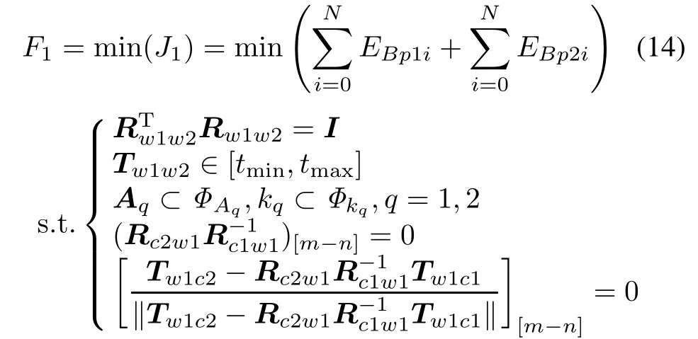
where the border of extrinsic T is expressed with tminand tmax,by the distortion parameters of two cameras are expressed and ΦAqand Φkq.
It is to say,after optimized parameters of each camera,we can achieve initial values of sx,r1,...,r9,Tx,Ty,f,Tzand k.
3.3 Multi-camera calibration optimization based on minimizing the vector differences of reprojection error
As shown in Fig.3,using high-precision calibration of two cameras as an example,in the cameras FOV we set the calibration points symmetrical,the purpose of multi-camera calibration based on minimizing the vectors difference of reprojection error is to reduce the difference of the magnitude and direction of reprojection error of the corresponding calibration point of two cameras.
In Fig.3,let the world coordinate of the calibration point in the left camera be P1i=(x1i,y1i,z1i)T.The reconstruction point of the world coordinate is.And the right camera is=.The reconstruction coordinate is=,among them i=1,...,n,n is the number of calibration points.The reprojection error vectors of the left and right cameras to the calibration points can be expressed as

In order to measure the difference of the camera calibration on the left and right sides,we define

It is a vector describing the reprojection error of the corresponding calibration point of two cameras.The magnitude and direction of the difference vector can be used to characterize the difference of the corresponding calibration points of multiple cameras.
According to the distribution characteristics of the calibration point,we can express vector errors of the cameras in the form of matrix as follows:
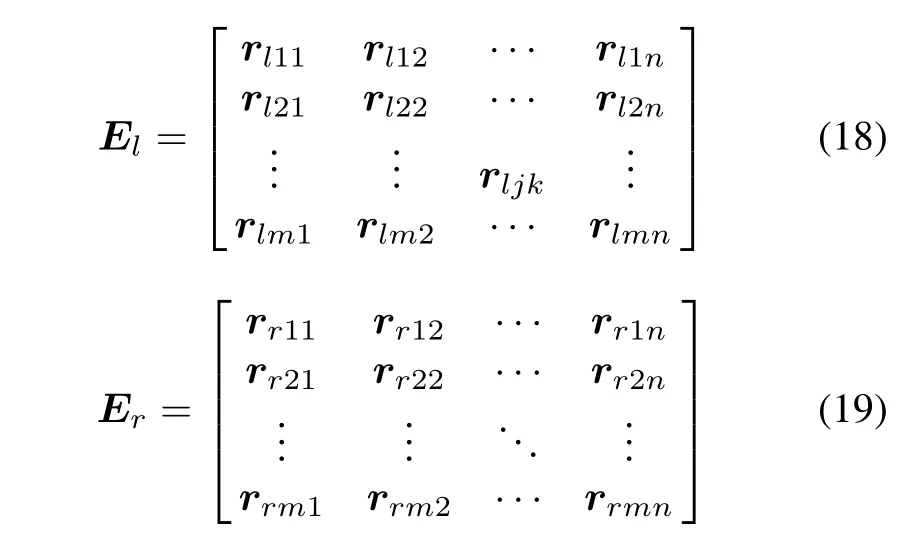
where rjkis the reprojection error vector of each calibration point.j and k are the calibration point rows and columns of unilateral camera’s FOV.m and n are the calibration point number of rows and columns in unilateral camera’s FOV,respectively.
The difference vector of all corresponding calibration points on the camera’s FOV can be expressed as

To solve the calibration parameters,the objective function can be optimized to minimize the norm of vector matrix∇E.Based on the analysis,is regarded as the objective function for optimization.
Proposition1 The direction angle betweenand∇r is positively related to the size.
Proof As shown in Fig.4,r1and r2are the reverse projection error vectors of the two cameras for the same calibration point.∇r and θ are the difference and angle between the two error vectors,respectively.The goal of multi-camera calibration optimization is to minimize the sum ofand θ.
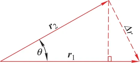
Fig.4 Definition of calibration point error vector

And since the derivative of θ for the objective function

f is an increase function of θ.
Because

Obtain the minimum value if and only if θ=0 and get the maximum value when θ=180◦.
Therefore,it can be defined as

which is the difference matrix between two cameras,and the matrix can be used to represent the calibration difference between the two cameras.When the two cameras are calibrated at the same time,the measurement error will be smaller under the condition of minimized difference matrix norms.
According to the definition of the difference matrix and the norm theory of the matrix,if we would like to have a smaller calibration difference of two cameras,we can get a set of parameters fr,kr1,Rr,Trfor the right camera,to make the difference matrix U minimized.We can optimize the following objective function:

After the left and right cameras have been calibrated by using the method in Section 1,assume the calibration results are the initial parameters,and the optimum parameters of the right camera are solved by Levenbery-Marquardt(LM),and make the Forbenius norm of the matrix the smallest,so the optimal parameters fr,kr1,Rr,Trof the right camera are obtained.
4.Experiments and results
In the calibration experiment,a certain number of calibration points are uniform set in the measurement field,and the 3D coordinates of the calibration point are measured by the 3D measurement equipment.Firstly,the cameras are calibrated by the traditional calibration method,and then using the multi-calibration algorithm for a number of high-precision camera calibrations,the specific steps are shown in Fig.5.
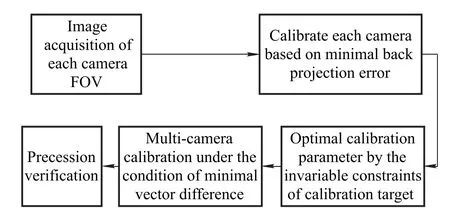
Fig.5 Multi-camera global calibration
The multi-camera calibration algorithm presented in this article is verified by synthetic test and real data test.
4.1 Synthetic data experiment
The calibration accuracy of camera parameters is affected by many factors.In order to realize the process of the multi-camera calibration algorithm presented in this paper,the calibration points are evenly distributed in the FOV of the camera,and the ideal image coordinates are produced using(1),and the Gauss white noise(snr∈[8,10],amplitude changes between 0-1 pixel)of different levels is added to the ideal coordinates,and then using the two multi-camera calibration algorithm in Section 2,as shown in Fig.6,the norm size of the difference matrix is statistical,in which the abscissa represents the level of noise,ordinate represents the calibration difference of cameras.Table1is is the camera parameter setting. The synthetic analysis software is Matlab 8.1.0.604.
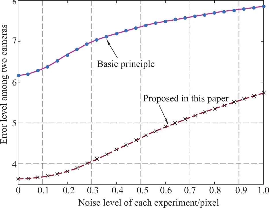
Fig.6 Curve of calibration difference matrix norm with the changes of noise level
It can be seen from Fig.6 that the difference of two cameras using the method proposed in this paper is better than the basic,obviously,and the norm of the difference matrix increases with increasing of the distortion noise of the image coordinate extracted,it indicates that:
(i)The calibration difference of two cameras of the method illustrated in this paper increases with increasing of noise.
(ii)For the proposed method,the noise level has a larger affect compared with the basic principle.
(iii)The visual measuring unit has a higher accuracy of 3D measurement by using the method proposed in this paper.

Table 1 Simulation parameter settings
4.2 Observation data experiment 1
The camera used in the experiment isIOI Flare 4M140MCX,the lens is 35 mm fixed focus,the 3D measurement equipment is Sokkia NET05AX,the target planeness is 2mm and the size is(L)14000mm×(H)7000mm.The global calibration experiment uses the basic method and that proposed in this paper based on large-scale calibration targets.
As shown in Fig.7,a certain number of circular calibration feature points follow symmetrical distribution,and the 3D coordinates of the calibration tags are measured by the total station to produce the large scale calibration target.For the experiment,the calibration point reprojection error is shown in Fig.8,and the error vector distribution is shown in Fig.9.
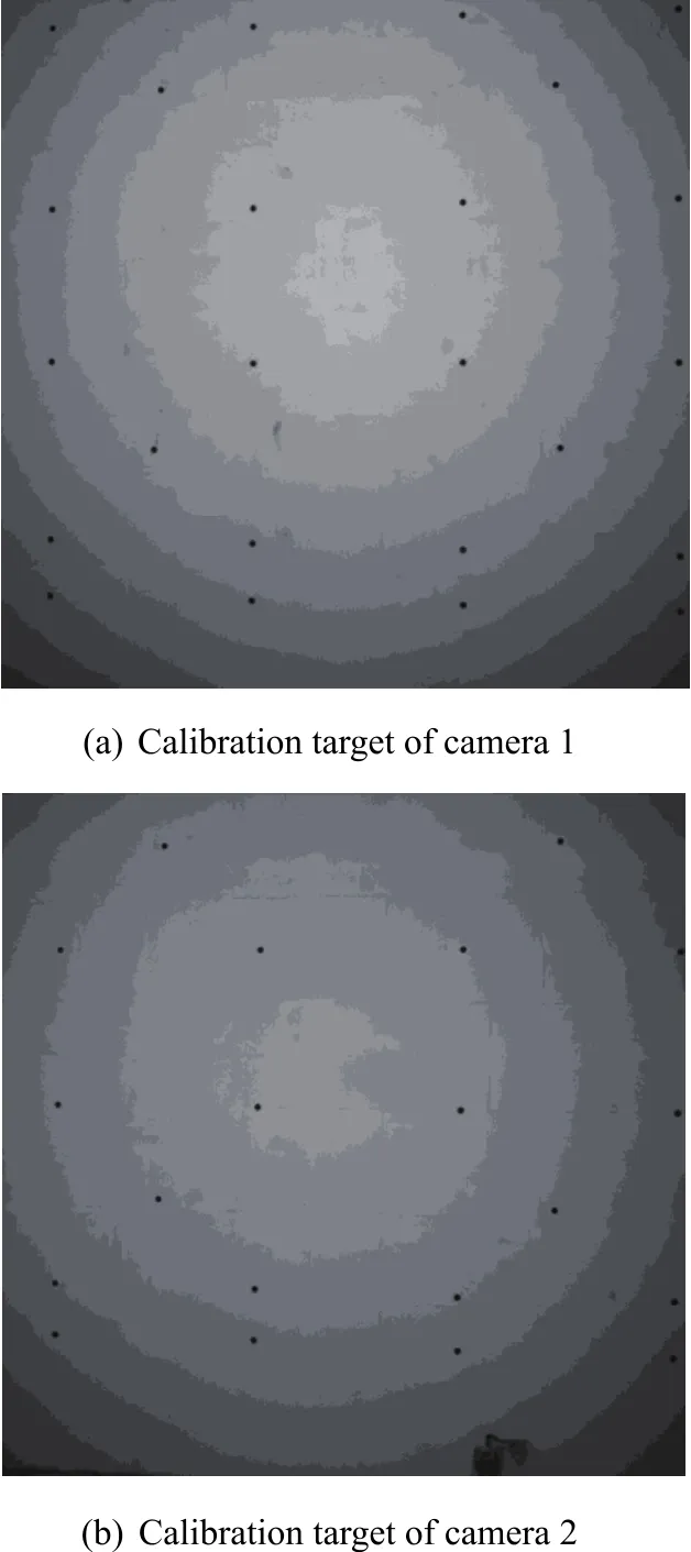
Fig.7 Large-scale calibration target of the camera
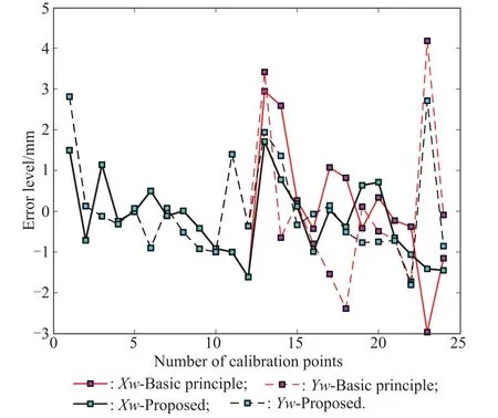
Fig.8 Reprojection error level of calibration points
As shown in Fig.8,after optimization using the constrains 1 and 2,we have follows:
(i)For the basic principle and that proposed in this paper,the maximum reprojction errors of calibration points are less than 5 mm and 3 mm,respectively;
(ii)According to Fig.8,the algorithm proposed in this paper makes the left and right cameras more consistent in the measurement of the spatial points,and the right camera reprojection error of calibration points is reduced by about 42%.
As shown in Fig.9,we have follows:
(i)Comparing with the basic principle,the differences of the reprojection error vector are more uniform and the maximum value is going down;
(ii)The error is larger than the basic principle in the origin of coordinates,and on the other hand it is an advantage of the proposed principle,because there is no situation that the reprojection error vector has sharp change.
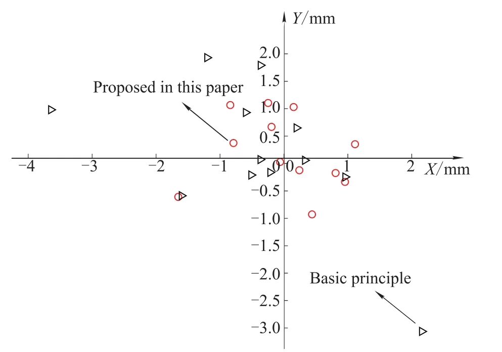
Fig.9 Calibration points difference of reprojection error vector distribution
4.3 Observation data experiment 2
In order to verify the proposed calibration method,an attitude angle measurement experiment is proceeded.The experiment result is shown in Fig.10.
From Fig.10,we have follows:
(i)The experimental results verify the feasibility and effectiveness of the proposed optimization algorithm to solve the problem that the measurement error changes dramatically due to the switching of the measurement camera.The two images in Fig.10 are the attitude solution results obtained by the basic calibration algorithm.
(ii)The following two images are the measurement results obtained by the calibration optimization algorithm proposed in this paper.From Fig.10,it can be seen that the jump problem of attitude measurement error has been solved by the method proposed in this paper,and the measurement accuracy is improved.
(iii)On the other hand,the distribution of attitude errors is slightly different,this is because the calibration parameters obtained by the calibration method proposed in this paper have been optimized compared with the basic calibration algorithm.
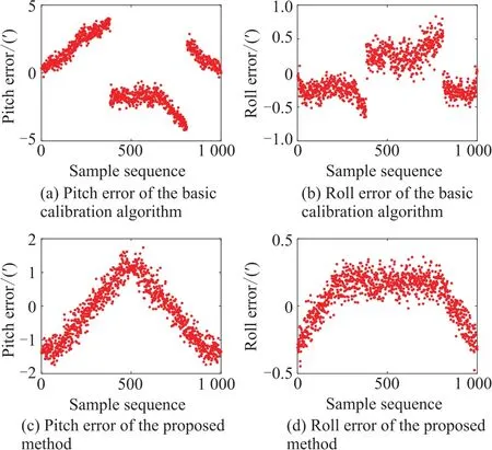
Fig.10 Altitude measurement error of two calibration methods
5.Conclusions
Based on the constraint conditions that the rigid body transformation relationship between multiple cameras is constant and the vector differences of reprojection error are minimized,a method of field calibration of visual measuring unit composed of multi-camera is proposed,which realizes the rapid calibration of multi-camera.To sum up,the following conclusions are drawn:
(i)The multi-camera calibration method proposed in this paper is superior to the multi-camera calibration method based on large-scale targets.
(ii)The global error vector distribution of the new method is more uniform than the basic method.
(iii)The multi-camera calibration method based on minimizing the vector differences of reprojection error has the characteristic of fewer steps and easy to operate on-site.
It should be noted that the method proposed in this paper needs to select a high performance camera as the reference camera,and a better flatness calibration target is needed.In the practical application,the method compared with the traditional multi-camera calibration method uses a more nonlinear optimization algorithm and the calculation speed is slow.Therefore,how to improve the algorithm’s operation speed is the future work.
