
Analysis of the cylinder block tilting inertia moment and its effect on the performance of high-speed electro-hydrostatic actuator pumps of aircraft
2018-02-02 08:10:24JunhuiZHANGQunCHAOBingXU
CHINESE JOURNAL OF AERONAUTICS 2018年1期
Junhui ZHANG,Qun CHAO,Bing XU
State Key Laboratory of Fluid Power and Mechatronic Systems,Zhejiang University,Hangzhou 310027,China
1.Introduction
The future development of general aircraft systems is directed towards more electric aircraft(MEA),in which traditional central hydraulic systems are replaced with local electrically powered actuation systems.1Successful application of the power-by-wire(PBW)technology to MEA makes EHAs easily realizable.Local electrically powered actuation systems have some potential advantages,such as weight reduction,power saving,and improved maintainability,over conventional central hydraulic systems.2–5As shown in Fig.1,a typical EHA system mainly consists of a variable-speed servo motor,afixed displacement and bi-directional axial piston pump,a symmetrical linear actuator,an accumulator,and some related valves,etc.In an EHA system,the symmetrical linear actuator of the primaryflight control surface is motivated using hydraulicfluid,the velocity and direction of which are controlled by thefluid flow from a servo motor driven hydraulic pump called EHA pump.The accumulator is mainly to maintain the pressure in the system,to cool the hydraulicfluid,and to compensate anyfluid loss over the lifetime of the actuator.
Fig.2 shows the general configuration of an axial piston pump,a type of EHA pump.The cylinder block is held tightly against the valve plate by means of a compressed cylinder block spring,while the valve plate is held in afixed position.There are several piston/slipper assemblies nested within the cylinder block at equal intervals about the centerline of the cylinder block.The slippers remain in a reasonable proximity with the swash plate utilizing a spherical cup and a holddown device called retainer.The shaft is coupled with the cylinder block using a spline mechanism and is supported by two bearings at both shaft ends.When the shaft is driven by a servo motor,the cylinder block rotates about the axis of the shaft and thus all the piston/slipper assemblies reciprocate within the cylinder bores because of the hold-down mechanism and the inclined swash plate.During rotation,thin oilfilms form between the cylinder block and the valve plate,between the pistons and the cylinder block,and between the slippers and the swash plate.These thin oilfilms serve as combined hydrostatic and hydrodynamic bearings respectively.However,a leakageflow occurs across the sliding interfaces due to the existence of these thin oilfilms.Unreasonable gaps between the sliding parts tend to increase the leakageflow as well as the potential for undesirable wear.
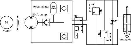
Fig.1 Schematic of an electro-hydraulic actuation system.
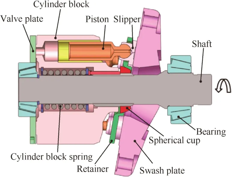
Fig.2 General configuration of an axial piston pump.
An EHA pump usually operates at a high speed of more than 10,000 r/min since a higher speed means a smaller displacement for a given volumetricflow of the actuator.Therefore,morecompactEHA pumpscanberealizedby increasing the pump speed,which is of importance for improving the power density of the EHA system.Messier-Bugatti and Parker claimed that they have produced very high-speed EHA pumps whose rotational speeds can even reach more than 15,000 r/min.For the aim of higher power density,the continuing development of EHA systems makes a further demand upon EHA pumps for greater rotational speeds.However,high-speed operating conditions will bring several practical problems imposed on EHA pumps.
Thefirst problem regards pressure pulsation.6,7The pressure within the cylinder block of an axial piston pump easily exhibits undershooting or overshooting when the pump is operating at a high speed.It is found that the undershooting orovershooting pressureincreasesalmostlinearly with increased rotational speed.
The second problem associated with a high speed is the cavitation.8–11An axial piston pump with a high speed is likely to be in accompany with obvious cavitation.On one hand,the pump speed should be limited below the critical speed that exactly causes cavitation.On the other hand,a higher suction tank pressure is needed for which a booster pump may be used.
The third problem of a high speed may be concerned with power losses.12–17Power losses arising from high speeds mainly involve friction losses due to metal-to-metal contact,and viscous friction and churning losses due to rotating elements interacting with thefluid filled in the pump case.Some special surface treatments of metals such as duplex TiN coatings14and novel structures such as Power BoostTM18have proven to beeffectivein reducing powerlossesthrough experimental studies.
The last problem caused by a high speed is the tilt of rotating parts in an axial piston pump.In the past decades,some theoretical and experimental research has been devoted to the slipper tilt.19–25It was found that the slipper tends to tilt away from the swash plate when a pump reaches a high speed.Although some academic attentions have been given to the cylinder block tilt,most studies were occupied with the traditional cylinder block tilt resulting from the pressure difference between the discharge and intake sides.26–30In reality,another type of cylinder block tilt due to the cylinder block tilting inertia moment produced by the inertia forces of piston/slipper assemblies cannot be ignored when a pump operates at a high speed.Ivantysynova et al.29,31,32included the inertia forces of piston/slipper assemblies in elastohydrodynamic(EHD)and thermoelastohydrodynamic(TEHD)models,but all these models were not applied to high-speed conditions and no detailed results about the influence of the cylinder block tilting inertia moment on the pump performance were presented.Manring10,33pointed out the inherent phenomenon of cylinder block tilt and derived the cylinder block tilting criteria;however,the expression for the cylinder block tilting inertia moment was not given explicitly in his study.
The goal of this study was to investigate the cylinder block tilt in a high-speed EHA pump from the point of view of dynamics.In the present work,an expression for the cylinder block tilting inertia moment was developed that included the translational inertia and centrifugal forces of a piston/slipper assembly.Moreover,high-speed tests on an EHA pump prototype were carried out to examine the effect of the cylinder block tilting inertia moment on the EHA pump performance.
2.Mathematical model
In order to better understand the reason for producing the cylinder block tilting inertia moment,the relevant forces acting on a single piston/slipper assembly,as shown in Fig.3,must be accurately defined.Point c in Fig.3 represents the centroid of the piston/slipper assembly.It should be emphasized that just the cylinder block tilting inertia moment will be discussed in this paper,so the relevant forces resulting in the tilting inertia moment only involve the translational inertia force Faand the centrifugal force Frof the piston/slipper assembly.
In this case,theXYZsystem isfixed in an inertial frame and thexyzsystem attached to the cylinder block rotates relative to theXYZsystem.Suppose that ρ and L are the position vectors of the centroid of the piston/slipper assembly and the center of the piston-slipper ball joint,respectively,relative to the origin in theXYZsystem.Then the absolute acceleration of the centroid of the piston/slipper assembly can be expressed in a vector form as34

where ω is the absolute angular speed of the cylinder block whose magnitude ω is assumed to be constant,subscriptnrepresents thenth piston/slipper assembly,and subscript r denotes that the scalar quantity or the vector quantity is described relative to thexyzsystem.
Before evaluating each term of Eq.(1),we note that35
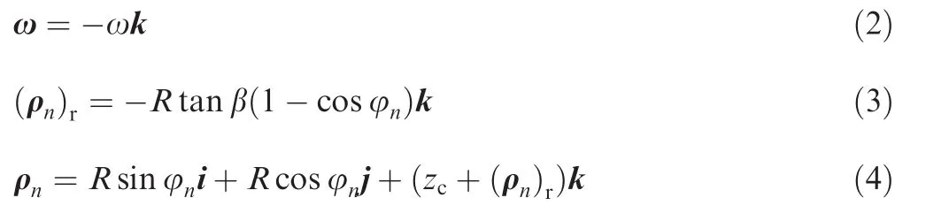
in which i,j,and k are the unit vectors in theX-direction,Y-direction,andZ-direction,respectively,Ris the pitch circle radius of piston bores,β is the swash plate angle,zcis the initial position of the centroid of thefirst piston/slipper assembly,and φnis the angular position of thenth piston.
If φ1=0 when the bottom dead center(BDC)is chosen as the position for the derivation of kinematic parameters,then

where α is the angular interval between two contiguous pistons about thez-axis.
From Eqs.(1)to(5),we obtain thefinal absolute acceleration of the centroid of thenth piston/slipper assembly as

in which thefirst term on the right side represents the centrifugal acceleration caused by the rotating motion along with the cylinder block about the negativeZ-direction,and the second term represents the translational acceleration due to the reciprocating motion relative to the cylinder block.
According to d’Alembert’s principle,the centrifugal acceleration will generate a radial centrifugal force Fr,and the translational acceleration will generate an axial inertia force Fa.If we treat the piston and slipper as a whole analytical object,then we may assume for convenience that the centrifugal force is transferred to the cylinder block and the axial inertia force is transferred to the swash plate.The reaction force FNfrom the swash plate results in a remaining lateral force FNythat produces the effect of cylinder block tilt,along with the centrifugal force Fr.Thus,taking moment about the origin,we obtain the cylinder block tilting inertia moment as follows:
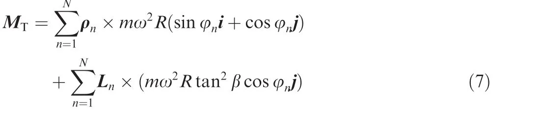
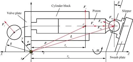
Fig.3 Forces acting on a single piston/slipper assembly.
wheremis the individual piston/slipper assembly mass,Nis the total number of pistons,and Lnis the moment arm of thenth lateral force,which can be obtained by

wherez0is the distance from the shaft reaction to theXYplane as shown in Fig.3.Substituting Eqs.(4)and(8)into Eq.(7),the cylinder block tilting inertia moment is given by
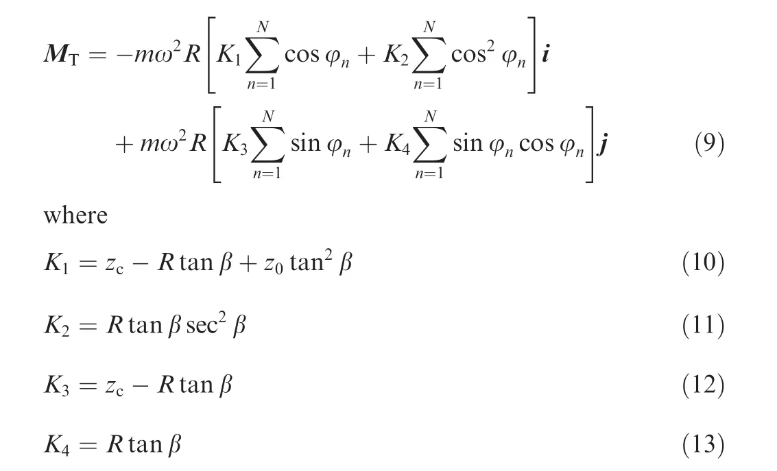
Considering that all pistons are nested in a circular array within the cylinder block at equal angular intervals about theZ-axis,then the following simplifications can be obtained due to mathematical symmetry:
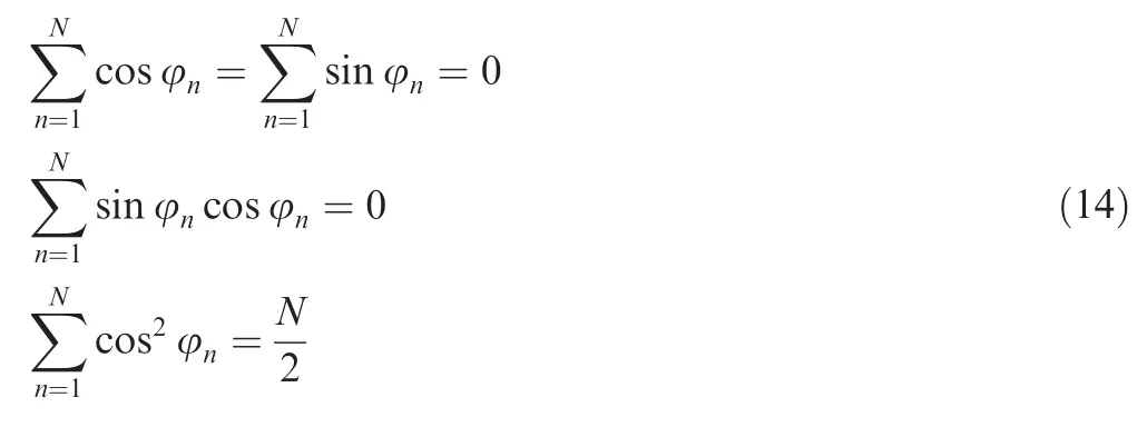
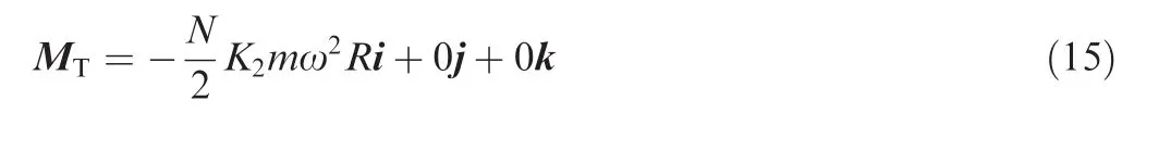
Finally,the cylinder block tilting inertia moment due to the centrifugal and translational accelerations presented in Eq.(9)can be reduced to a simplified form as follows:
3.Analysis and discussion
It can be seen from Eq.(15)that the centrifugal and axial inertia forces of the piston/slipper assembly only produce a tilting inertia moment in the negativeX-direction,which results in the cylinder block tilting towards the bottom dead center(BDC),as shown in Fig.4 where the gap between the cylinder block and the valve plate has been magnified for illustration purpose.In reality,the oilfilm thickness between the cylinder block and the valve plate is usually on the order of magnitude of microns between 0 and 100 μm based upon measured and simulated results.26–29
It has to be pointed out that the tilting inertia moment MTis exactly perpendicular to the moment acting on the cylinder block by the pressure distribution along the discharge and intake sides,Mmean.This hydraulic moment is the traditional moment that determines the cylinder block balance about theY-axis.Therefore,this tilting inertia moment MTcannot be counteracted byMmeandirectly,and a potential metal-tometal contact and an increased leakageflow are likely to occur across the cylinder block/valve plate interface.
Although direct measurement of the oilfilm thickness between the cylinder block and the valve plate at a high pump speed was not carried out in this paper,previous experimental investigations into the cylinder block/valve plate pair have been performed at low pump speeds.26–28,36In the literature36,three micro position transducers GS1,GS2,and GS3 were mounted between the cylinder block and the valve plate at certain angular intervals,as shown in Fig.5.Transducers GS1 and GS2 are located in the vicinity of the top dead center(TDC),and transducer GS3 is close to the BDC.
Fig.6 gives the actual oilfilm thicknesses respectively through three displacement transducers.It is found that the oilfilm thickness between the cylinder block and the valve plate is significantly dependent on the pump speed.The oilfilm thicknesses measured through GS1 and GS2 increase with an increased pump speed,while the oilfilm thickness measured through GS3 decreases with an increased pump speed.This may be explained by the fact that the tilting effect of the cylinder block due to the tilting inertia moment(see Eq.(15))strengthens with an increased pump speed,resulting in the cylinder block tilting towards the BDC.
The tilting effect of the cylinder block may not trigger catastrophic machine failures at a low pump speed.On one hand,the occurrences of a hydrodynamic effect and a thermal wedge effect between the cylinder block and the valve plate will prevent the cylinder block from serious tilt.On the other hand,a low pump speed means a small tilting inertia moment acting on the cylinder block and thus will not bring a significant difference for the cylinder block balance.However,this tilting effect can no longer be neglected once the EHA pump reaches a high speed(e.g.,more than 10000 r/min).Fig.7 shows the dependence of the tilting inertia moment on the pump speed for different discharge pressures of 2,5,10,and 20 MPa.
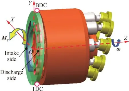
Fig.4 Cylinder block tilting towards the BDC.
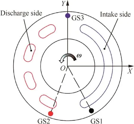
Fig.5 Transducer positions located between the cylinder block and the valve plate for oilfilm thickness measurement.
It has to be noted that the tilting inertia moment value has been normalized by the above mentioned hydraulic momentMmeanas follows:37

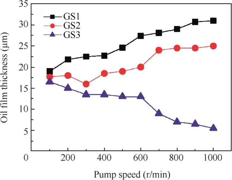
Fig.6 Actual oilfilm thickness between the cylinder block and the valve plate for a discharge pressure of 1.6 MPa.36
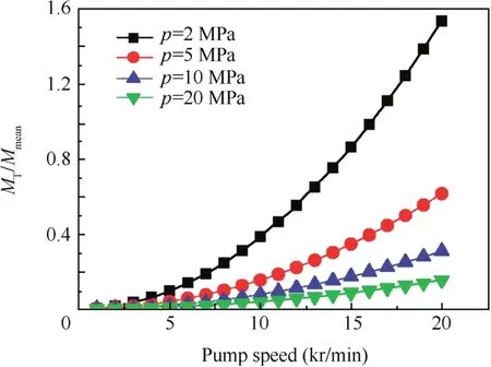
Fig.7 Normalized tilting inertia moment of the cylinder block.
wherepis the discharge pressure,R1andR2are the inside and outside radii of the inner sealing land on the cylinder block,respectively,R3andR4are the inside and outside radii of the outer sealing land on the cylinder block,respectively,and α1is the angular span of the cylinder block kidney,as depicted in Fig.8.
Fig.7 indicates that the tilting inertia moment increases dramatically with the pump speed since it is proportional to the square of the pump speed as presented in Eq.(15).The tilting effect of the cylinder block due to the centrifugal and axial inertia forces of the piston/slipper assembly may be negligible at low speeds in engineering practice.However,it cannot be ignored especially when the EHA pump operates at a high speed and a low discharge pressure.For example,the tilting inertia moment can be about 1.5 times of the hydraulic moment produced by the pressure distribution between the cylinder block and the valve plate when the EHA pump speed reaches 20000 r/min.This considerable additional tilting inertia moment may lead to metal-to-matal contact and wedgeshaped oilfilm across the cylinder block/valve plate interface.
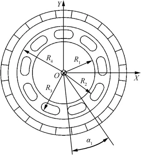
Fig.8 A schematic configuration of the cylinder block bottom face.
4.Experiments
In order to estimate the EHA pump performance at a high rotational speed,a high-speed test rig that could provide a drive speed up to16000 r/min was set up,as shown in Fig.9.
It is important to underline that the performance tests were conducted at variable rotational speeds from 1000 r/min to 9000 r/min for constant pressures of 2,5,10,and 20 MPa,respectively.The swash plate was held in afixed position at a certain inclined angle with respect to the cylinder block during the tests.The EHA pump prototype had a theoretical volumetric displacement of 3 mL/r.The inlet oil temperature was maintained at(20± 1)°C with the aim to eliminate the impact of the inlet oil temperature on the pump performance as much as possible.
As mentioned previously,a high rotational speed tends to trigger the cylinder block tilting away from the valve plate,resulting in subsequent increased leakage and potential wear between the cylinder block and the valve plate.It seems that the leakageflow from the cylinder block/valve plate should be measured directly to investigate the effect of the cylinder block tilting inertia moment on the EHA pump prototype performance.However,it was extremely difficult for us to measure the leakageflow from the cylinder block/valve plate interface separately from other leakage sources such as the piston/cylinder block interface and the slipper/swash plate interface.Therefore we measured the pump case drain leakageflow instead of the leakageflow from the cylinder block/valve plate interface.Inaddition,wepaidourattentiontothewearpatternofthesliding surface between the cylinder block and the valve plate attempting to predict the occurrence of cylinder block tilting.
The trend of the pump case drain leakageflowQLof the investigated EHA pump prototype at different pump speeds for discharge pressures of 2,5,10,and 20 MPa is shown in Fig.10(a).Fig.10(a)highlights that the pump case drain leakageflow increases with an increased pump speed,which is consistent with the tendency of the cylinder block tilting inertia moment shown in Fig.7.Furthermore,it can be seen from Fig.10 that the pump case drain leakageflow at a speed higher than 5000 r/min increases more sharply than that lower than 5000 r/min,which may be partly explained by the fact that the tilting effect of the cylinder block is quite significant when the EHA pump operates at a high rotational speed.It can be observed from Eq.(15)that the cylinder block tilting inertia moment is a function of the pump speed.However,the pump case drain leakageflow is the comprehensive results of the pump pressure and speed.In order to estimate the dependence of the tilting effect of the cylinder block on the pump speed,the relative pump case drain leakageflow is compared between these four different discharge pressures.The relative pump case drain leakage is defined as the ratio of the leakage flow at a certain pump speed to that at 1000 r/min,QL1000.Fig.10(b)demonstrates that the pump case drain leakageflow at a low pressure is more dependent on the pump speed than that at a high pressure.
Considering that only comparing the measured pump case drain leakage flow at a variety of pump speeds is not sufficient enough to reveal the characteristics of the cylinder block tilting behavior,more detailed investigation should be further provided.After accomplishing the general performance tests on the EHA pump prototype,the EHA pump was dismantled for the purpose of insight into the sliding surface between the cylinder block and the valve plate,as shown in Fig.11.It can be observed that the non-sealing land of the cylinder block suffered more severe wear than the sealing land,which implies that the cylinder block was likely to tilt away from the valve plate and consequently a metal-to-metal contact between the cylinder block and the valve plate took place.
By the way,it can be seen from the right-hand side of Fig.11 that an obvious wear difference of the valve plate sliding surface appears between the intake and discharge sides,which is attributed to the unbalanced hydraulic moment between the discharge and intake sides.However,this kind of wear is not the focus of this paper as there is sufficient literature concerned with it.26–30At this point,much more attention will be given to the specified wear of the valve plate sliding surface in the vicinities of the TDC and the BDC.
The sliding surface profiles of the cylinder block and the valve plate were detected by a trilinear coordinates measuring instrument and a surface roughness measuring instrument,respectively,asshowninFig.12.Inordertocomparethesliding surfaceprofilesofthecylinderblockbeforeandafterhigh-speed tests,the relative heights(relative to a certain non-sliding plane)of nine points located on the cylinder block sliding surface were measured,asshowninFig.13.Theseninemeasuredpointswere dividedintothree groups(i.e.,A,B,andC),andeachgrouphad threepoints.(i.e.,Ai,Bi,andCi,i=1,2,3).Thesepointsofeach group were arranged in the same radial direction since the wear difference of the sliding surface along the radial direction could reflect the wear pattern of the sliding surface.
Fig.14 shows the measured heights of all the points shown in Fig.13 before and after high-speed tests.It remains to be noted that the horizontal coordinate represents the ID numbers of the points that are located in the same radial direction,and the vertical coordinate represents the relative height of the cylinder block sliding surface before and after tests.A smaller relative height means an occurrence of more serious wear at the corresponding location.
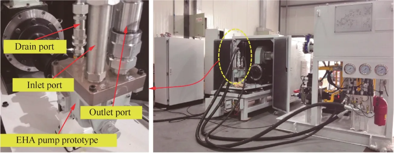
Fig.9 Test rig for performance tests on the high-speed EHA pump prototype.
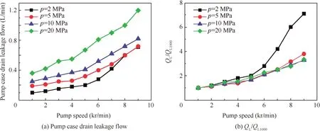
Fig.10 Pump case drain leakageflow vs pump speed for different discharge pressures of 2 MPa,5 MPa,10 MPa,and 20 MPa.
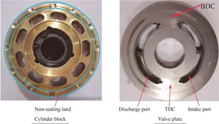
Fig.11 Photograph of the sliding surface between the cylinder block and the valve plate after being dismantled.
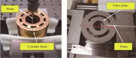
Fig.12 Sliding surface profile measurements of the cylinder block and the valve plate.
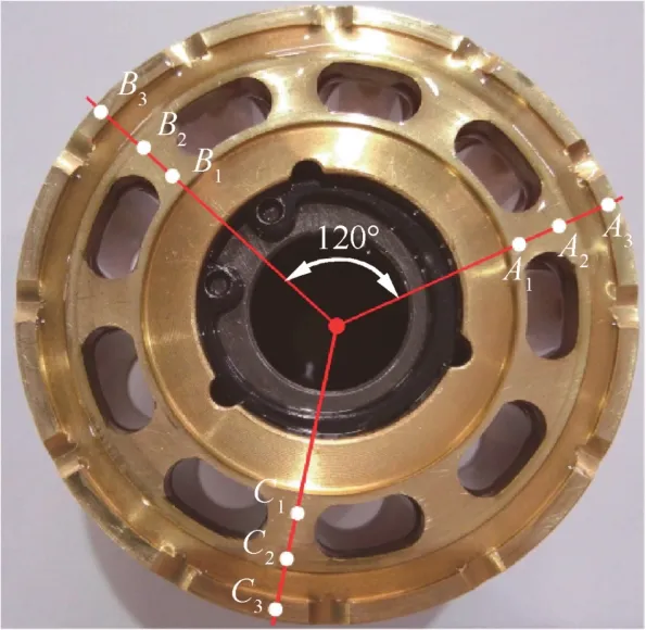
Fig.13 Measured points located on the cylinder block sliding surface.
It can be concluded that wear of the cylinder block sliding surface took place during the pump operation by comparing Fig.14(a)and(b).In addition,the various relative height reductions from point 1 to point 3 in each group in Fig.14(b)indicate that more serious wear occured near the outside region of the cylinder block sliding surface than near the inside region.In other words,the sliding surface of the cylinder block that was subject to both the tilting inertia moment and the unbalanced hydraulic moment changed from a flat configuration to a convex configuration during rotation.
This finding confirms the existence of a cylinder block tilt when the cylinder block rotates on the sliding surface of the stationary valve plate.However,the cylinder block tilt cannot be simply attributed to the tilting inertia moment described in this paper without further investigation.As previously mentioned,the unbalanced hydraulic moment between the discharge and intake sides can also result in a cylinder block tilt and consequently lead to wear of the sliding surface between the cylinder block and the valve plate.Therefore,the sliding surface profile of the stationary valve plate needs to be measured,in combination with the measurement of the cylinder block sliding surface profile.
As shown in Fig.12,the probe of the surface roughness measuring instrument moved along the TDC/BDC axis that was in the same direction as the arrow.The real sliding surface profiles at the TDC and BDC vicinities are demonstrated in Fig.15 from which it can be observed that the surface roughness value in the vicinity of the BDC is smaller than that in the vicinity of the TDC.This observation agrees with the previous analysis in this research,which predicts that the tilting inertia moment attempts to make the cylinder block tilt towards the BDC,as shown in Fig.4,and thus the sliding surface region close to the BDC has more opportunity to get a metal-tometal contact than that close to the TDC.Furthermore,the above observation partly explains the fact that the pump case drain leakageflow increases dramatically with the pump speed because a wedge-shaped oilfilm forms across the cylinder block/valve plate interface due to the cylinder block tilt.
Additionally,comparing the wear condition between the cylinder block and the valve plate,wefind that the cylinder block suffered more serious wear than the valve plate.This is because the material of the cylinder block is soft brass while that of the valve plate is nitrided steel.
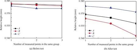
Fig.14 Relative heights of measured points before and after high-speed tests.
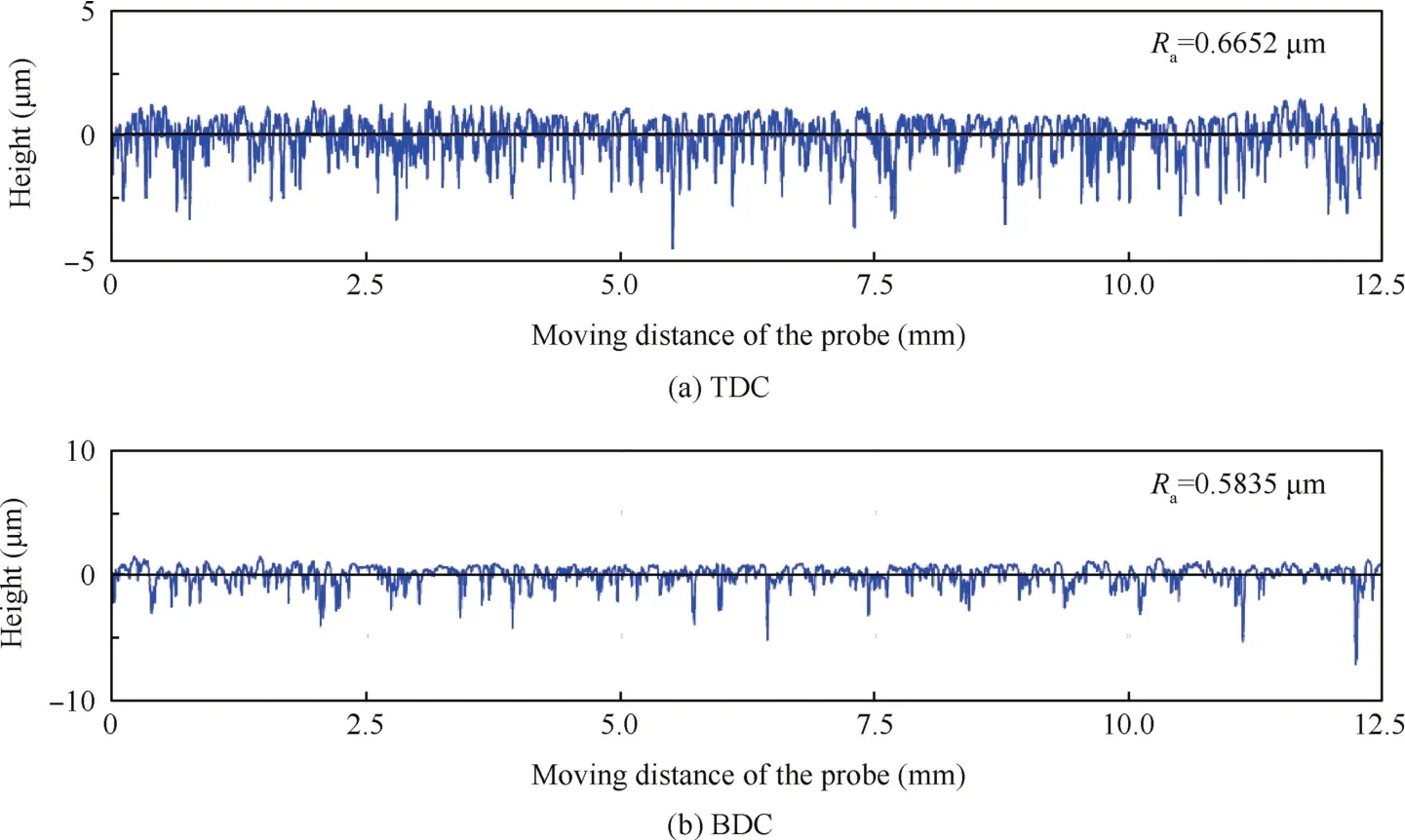
Fig.15 Surface roughness measurements in the TDC and BDC vicinities.
5.Conclusions
The tilting inertia moment exerted on the cylinder block by piston/slipper assemblies has been derived in this paper in order to examine the effect of the tilting inertia moment on the cylinder block tilt.Based on analytical and experimental results,the following conclusions may be drawn:
1.The tilting inertia moment acting on the cylinder block by the inertia forces of a piston/slipper assembly can be attributed to the centrifugal and translational accelerations of the piston/slipper assembly.
2.The tilting inertia moment produced by a piston/slipper assembly has a significant effect on the cylinder block tilt.This tilting effect attempts to make the cylinder block tilt towards the BDC,which can give rise to the occurrence of metal-to-metal contact between the cylinder block and the valve plate in the vicinity of the BDC.
3.The cylinder block tilt due to the tilting inertia moment also causes an obvious increase in the pump case drain leakageflow because the cylinder block tilting behavior contributes to a wedge-shaped oilfilm across the cylinder block/valve plate interface.
4.The cylinder block tilt within an EHA pump is an inherent phenomenon which cannot be ignored especially at high speeds.In an EHA pump design,the tilting inertia moment should be taken into account when performing the force balance analysis of the cylinder block.
5.The tilting inertia moment acting on the cylinder block could be reduced to some extent by introducing some novel structures or parameter optimization for an EHA pump design.For example,according to Eq.(15),light pistons could be adopted instead of common ones to decrease the tilting inertia moment.
Acknowledgements
The authors would like to thank the National Basic Research Program of China(No.2014CB046403)and the National Natural Science Foundation of China(No.U1509204)for theirfinancial supports.
1.Andersson J,Krus P,Nilsson K.Optimization as a support for selection and design of aircraft actuation systems.Optimization1998;98:39843.
2.Crowder R,Maxwell C.Simulation of a prototype electrically powered integrated actuator for civil aircraft.Proc Inst Mech Eng G-J Aerosp Eng1997;211(6):381–94.
3.Navarro R.Performance of an electro-hydrostatic actuator on the F-18 systems research aircraft.Washington,D.C.:NASA;1997.Report No.:NASA/TM-97-206224.
4.Dominique VDB.The A380flight control electrohydro-static actuators,achievements and lessons learnt.25th International Congress of the Aeronautical Sciences;2006 Sep 3–8;Hamburg,Germany.2006.p.1–8.
5.Chakraborty I,Mavris DN,Emeneth M,Schneegans A.A methodology for vehicle and mission level comparison of more electric aircraft subsystem solution:application to theflight control actuation system.Proc Inst Mech Eng G-J Aerosp Eng2014;229(6),0954410014544303.
6.Edge KA,Darling J.The pumping dynamics of swash plate piston pumps.JDynSystMeasControl-TransASME1989;111(2):307–12.
7.Carsten FB,Lu¨XJ,Stanislav S.Pressure compensator(PC)pressure overshoot analysis and experimental research of an open circuit pump.2015 International Conference on Fluid Power and Mechatronics(FPM);2015 Aug 5-7;Harbin,China.2015.p.910–13.
8.Harris RM,Edge KA,Tilley DG.The suction dynamics of positive displacement axial piston pumps.J Dyn Syst Meas Control-Trans ASME1994;116(2):281–7.
9.Yamaguchi A,Takabe T.Cavitation in an axial piston pump.Bull JSME1983;26(211):72–8.
10.Manring ND,Mehta VS,Nelson BE,Graf KJ,Kuehn JL.Scaling the speed limitations for axial-piston swash-plate type hydrostatic machines.J Dyn Syst Meas Control-Trans ASME2014;136(3):031004.
11.Kumar S,Bergada JM.The effect of piston grooves performance in an axial piston pumps via CFD analysis.Int J Mech Sci2013;66:168–79.
12.Olsson H.Power losses in an axial piston pump used in industrial hydrostatic transmissions.Proceedings of the 8th Scandinavian International Conference on Fluid Power;2003 May 7–9;Tampere,Finland.2003.p.491–505.
13.Hong YS,Doh YH.Analysis on the friction losses of a bent-axis type hydraulic piston pump.KSME Int J2004;18(9):1668–79.
14.Lee SY,Kim SD,Hong YS.Application of the duplex TiN coatings to improve the tribological properties of electro hydrostatic actuator pump parts.Surf Coat Technol2005;193(1):266–71.
15.Rahmfeld R,Marsch S,Go¨llner W,Lang T,Dopichay T,Untch J.Efficiency potential of dry case operation for bent-axis motors.Proceedings of the 8th International Fluid Power Conference(IFK);2012 Mar 26–28;Dresden,Germany.2012.p.73–86.
16.Theissen H,Gels S,Murrenhoff H.Reducing energy losses in hydraulic pumps.Proceedings of the 8th International Conference on Fluid Power Transmission and Control;2013 Apr 9–11;Hangzhou,China.2013.p.77–81.
17.Xu B,Zhang JH,Li Y,Chao Q.Modeling and analysis of the churning losses characteristics of swash plate axial piston pump.2015 International Conference on Fluid Power and Mechatronics(FPM);2015 Aug 5–7;Harbin,China.2015.p.22–6.
18.Parker Hannifin.Added power for your saw motor– a simple way to boost performance.2005.Available from:www.parker.com/euro_mcd.
19.Hooke CJ,Kakoullis YP.The effects of centrifugal load and ball friction on the lubrication of slippers in axial piston pumps.6th International Fluid Power Symposium;1981 Apr 8–10;Cambridge,England.1981.p.179–91.
20.Hooke CJ,Li KY.The lubrication of slippers in axial piston pumps and motors—the effect of tilting couples.Proc Inst Mech Eng C-J Mec1989;203(5):343–50.
21.Koc E,Hooke CJ.Considerations in the design of partially hydrostatic slipper bearings.Tribol Int1997;30(11):815–23.
22.Harris RM,Edge KA,Tilley DG.Predicting the behavior of slipper pads in swashplate-type axial piston pumps.J Dyn Syst Meas Control-Trans ASME1996;118(1):41–7.
23.Manring ND.Slipper tipping within an axial-piston swash-plate type hydrostatic pump.ASME International Mechanical Engineering Congress and Exposition;1998 Nov 15–20;Anaheim,California,USA.1998.p.169–75.
24.Manring ND.Predicting the required slipper hold-down force within an axial-piston swash-plate type hydrostatic pump.ASME International Mechanical Engineering Congress and Exposition;2001 Nov 11–16;New York,USA.2001.p.2513–22.
25.Borghi M,Specchia E,Zardin B,Corradini E.The critical speed of slipper bearings in axial piston swash plate type pumps and motors.2009 ASME Dynamic Systems and Control Conference;2009 Oct 12–14;Hollywood,California,USA.2009.p.267–74.
26.Kim JK,Jung JY.Measurement offluid film thickness on the valve plate in oil hydraulic axial piston pumps(I)-bearing pad effects.KSME Int J2003;17(2):246–53.
27.Kim JK,Kim HE,Lee YB,Jung JY,Oh SH.Measurement offluid film thickness on the valve plate in oil hydraulic axial piston pumps(Part II:Spherical design effects).J Mech Sci Technol2005;19(2):655–63.
28.Deeken M.Simulation of the tribological contacts in an axial piston machine.2004 ASME International Mechanical Engineering Congress and Exposition;2004 Nov 13–20;Anaheim,California,USA.2004.p.71–5.
29.Wieczorek U,Ivantysynova M.Computer aided optimization of bearing and sealing gaps in hydrostatic machines—the simulation tool CASPAR.Int J Fluid Power2002;3(1):7–20.
30.Bergada JM,Davies DL,Kumar S,Watton J.The effect of oil pressure and temperature on barrelfilm thickness and barrel dynamics of an axial piston pump.Meccanica2012;47(3):639–54.
31.Ivantysynova M,Lasaar R.An investigation into micro-and macrogeometric design of piston/cylinder assembly of swash plate machines.Int J Fluid Power2004;5(1):23–36.
32.Chacon R,Ivantysynova M.An investigation of the impact of micro surface on the cylinderblock/valve plate interface performance.8th FPNI Ph.D Symposium on Fluid Power;2014 June 11–13;Lappeenranta,Finland.2014.p.V001T02A006 –V001T02A006.
33.Manring ND.Tipping the cylinder block of an axial-piston swashplate type hydrostatic machine.J Dyn Syst Meas Control-Trans ASME2000;122(1):216–21.
34.Greenwood DT.Principlesofdynamics.Englewood Cliffs(NJ):Prentice-Hall;1988.
35.Ivantysyn J,Ivantysynova M.Hydrostatic pumps and motors.New Dehli:Akademia Books International;2001.
36.Zhao YX.The research of valve plate failure for swashplate piston pump.Chinese Hydraul Pneum.2010;5:64–8[Chinese].
37.Zhai PX.The design of swash-plate axial piston pump.Beijing:Coal Industry Press;1978[Chinese].
 CHINESE JOURNAL OF AERONAUTICS2018年1期
- CHINESE JOURNAL OF AERONAUTICS的其它文章
- Guide for Authors
- An aviation oxygen supply system based on a mechanical ventilation model
- Influence of TiB2particles on machinability and machining parameter optimization of TiB2/Al MMCs
- An investigation on adaptively machining the leading and tailing edges of an SPF/DB titanium hollow blade using free-form deformation
- A direct position determination method with combined TDOA and FDOA based on particlefilter
- Rapid and robust initialization for monocular visual inertial navigation within multi-state Kalmanfilter