
Research on a toolpath generation method of NC milling based on space-filling curve①
2017-12-19 00:39:41SuiXiulin隋秀凛ChenXiaoqiGeJianghuaJiaoYan
High Technology Letters 2017年4期
Sui Xiulin (隋秀凛), Chen Xiaoqi, Ge Jianghua, JiaoYan
(Department of Mechanical and Power Engineering, Harbin University of Science and Technology, Harbin 150080, P.R.China)
Research on a toolpath generation method of NC milling based on space-filling curve①
Sui Xiulin (隋秀凛)②, Chen Xiaoqi, Ge Jianghua, JiaoYan
(Department of Mechanical and Power Engineering, Harbin University of Science and Technology, Harbin 150080, P.R.China)
Tool path generated by space-filling curve always turns frequently causing trembling to machine, reducing toollife and affecting workpiece quality. Length and generation time of tool paths are both relatively long. In order to solve these problems, a toolpath generation method of NC milling based on space-filling curve is proposed. First, T-spline surface is regarded as the modeling surface, the grid, which is based on the limited scallop-height, can be got in the parameter space, and the influence value of grid node is determined. Second, a box is defined and planned, and the tool paths are got preliminarily,which is based on minimal spanning tree; Finally, based on an improved chamfering algorithm, the whole tool paths are got. A simulation system is developed for computer simulation, and an experiment is carried out to verify the method. The results of simulation and experiment show that the method is effective and feasible, and length and time of the tool paths are reduced.
space-filling curve, toolpath generation method, NC milling, T-spline surface, minimal spanning tree
0 Introduction
With rapid development of technology in the field of machinery, aviation and other fields, performance and appearance of the products are becoming more beautiful and better, and the surface which needs to process becomes more and more complex. The methods of the NC machine and machine center are row cutting, contour-parallel and space-filling curve (SFC)[1,2]. In complex surface, SFC is better than other methods. Scholars have studied the application of SFC in the tool path planning in different degrees, but there are still a lot of problems needing to be solved. For example, the mapping that the tool paths map from the parameter space to the machining surface, how to refine and segment the complex surface with the mesh consisting of regular rectangles, the tool paths always turn frequently, and they always cause trembling to machine, reducing the life of tool, affecting the quality of workpiece[3,4]. T-spline surface is a good modeling surface with water-tightness. When a model is established, T-spline surface is just a single-curved one, and there is no need to refine and segment the complex surface[5,6].
T-spline surface has a parameter space and a Euclidean space, which has an unified expression. In these two spaces, the mapping is one-to-one, the topology structure of data and the structure of the grid are the same. Owing to the permission that T-node can be used for modeling, there are many irregular rectangles, which can be used to establish the model better[7,8]. So T-spline surface is regarded as the modeling surface in this paper. The grid, which is based on the limited scallop-height, can be got in the parameter space, and the influence value of grid node is determined. Then a Box is defined and planned, and the tool paths which are based on minimal spanning tree (MST) are got preliminarily. At last, based on the improved chamfering algorithm, the whole tool paths are got.
1 Planning of grid
1.1 SFC and T-spline surface
1.1.1 Principle of SFC
SFC is a method of reducing dimension. SFC maps data in high-dimensional space to data in linear space, and classical linear index structure can store data in high-dimensional space. SFC includes Hilbert curve, Z curve and Gray curve.
As shown in Fig.1(a), the basic Hilbert curve is a gird curve that consists of 4 grids, which center points (R0、R1、R2、R3) are connected together. If the order of the basic Hilbert curve is 1, in order to obtain the order of i Hilbert curve, each grid of the basic Hilbert curve should be filled by the (i-1) order Hilbert curve, based on the rotation operation.
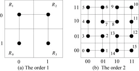
Fig.1 Hilbert curves of order 1 and 2
Rotation operation: In R0, the (i-1) order curve should rotate 180° according to the vertical axis and then rotate 90° according to plane clockwise. In R1and R2, the (i-1) order curve keeps it as it is. In R3, the (i-1) order curve should rotate 180° according to the vertical axis and then rotate 90° according to counterclockwise. The order 2 Hilbert curve is shown in Fig.1(b).
1.1.2 Principle of T-spline surface
If a T-spline surface is composed of n control points, S(u, v) is defined as
(1)
where, Bi(u, v) is the mixture function of B-spline basis functions; Piis control point, and Wiis the weight.
If Bi(u, v) is mixed with Wi, the Ri(u, v) is defined as
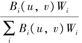
(2)
Substituting Eq. (2) into Eq. (1), the formula of T-spline surface can be defined as
(3)
According to Eq. (3), the coordinate of the points on the T-spline surface in Euclidean space can be regarded as a linear combination of the control points. Because of the mapping between the parameter space and the Euclidean space, the points are also corresponding.
In this paper, based on the principle of SFC, tool paths are planned in the parameter space, and then the paths are mapped into the Euclidean space to guide the processing.A five axis machining center shown in Fig.2(a) can be used to machine, and ball-end cutter shown in Fig.2(b) can be used to mill.
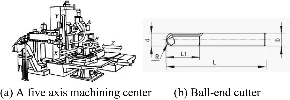
Fig.2 Five axis machining center and ball-end cutter
1.2 Generation of grid in parameter space
ξ is the scallop-height value in cutting parameters, L is the lateral step,R is the radius of curvature of the point, and r is the tool radius. Based on the different situation, L has different size as
(4)
(5)
(6)
Generation of grid is defined as follows. For example, in the v direction, parameter line v0is treated as the initial boundary, and arbitrary k sampling points are chosen. According to Eq. (4), Eq. (5) and Eq. (6), L1, L2, L3,…,Lkare the lateral step size of these sampling points. Based on the minimum algorithm, the minimum lateral step is set like this: Lmin=Min{L1, L2, L3,…, Lk}. And then set the bias distance l as follows: l=Lmin, and v1the next parameter line of v0. Taking the boundary of the workpiece as the end boundary, the parameter sequence lines of the v direction are finally obtained.
According to the same principle, the parameter sequence lines of the u direction can be generated. Intersecting the parameter sequence lines of the v direction and the u direction, the grid is set as the grid in parameter space of T-spline surface. The intersections are grid nodes, and these grid nodes correspond to the grid points in the Euclidean space.
2 Planning of tool path
2.1 Influence value of grid nodes
Influence value of a grid node is defined as follows: the coordinate of grid node p, in parameter space, is (u, v), and the corresponding grid point in the Euclidean space is p′(x, y, z). Substitute p(u, v) into Eq. (2), and get the rational influence value Er:
Er=R(u, v)
(7)
Influence value Ezwith p′(x, y, z) in z direction is defined as
Ez=δ(z-zo)
(8)
where, δ is the influence parameter of the z direction, which is a man-made setting, and the size of it is 0≤δ≤1. zois the difference between the machine coordinate system and the workpiece coordinate system.
Substituting Eq. (7) and Eq. (8) into Eq. (9), Epis the influence value of p.
Ep=Erωr+Ezωz
(9)
where, ωris the weight of Er, ωzis the weight of Ez.
In this paper, Erand Ezare regarded as the same significance, and ωz=ωr=1. Eq. (9) is redefined as follows:
Ep=Er+Ez
(10)
Especially, if Ez=0, the influence value Ep=0. And the place at p′ is non machining area.
2.2 Planning of box
2.2.1 Composition and division of box
If the adjacent four grid nodes can form a rectangle, the influence value of each of them is not zero. The four grid nodes are connected to form a box, and the connection lines of the grid node are called the edges of the box.
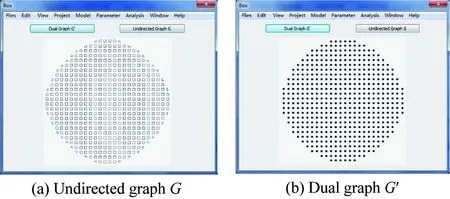
When establishing a model, the T-spline surface is a single-curved one, which will cover the irregular boundary and the hole on the workpiece. If the grid nodes fall into the hole or irregular boundary, they will affect the composition of box. Fig.3(a) is the undirected graph G of box, Fig.3(b) is the dual graph G′ of box, and the gray part is the shape of the workpiece in the parameter space. As Fig.3(a) shows, the situations, which like A, B, C and D,may not be able to generate a box. For these illegal boxes, some rules are defined in this paper as follows:
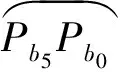
Situation A: The reason for this situation is that there is an odd column or row in the grid, and the boundary section is not included in the grid. To solve this problem, the rules which are shown in Fig.4(a) should be followed. Pa1and Pa2are the gird notes on odd column or row. Pa3and Pa4are the notes selected on the boundary, and Pa1Pa2must be perpendicular to Pa1Pa3and Pa2Pa4. The influence value of Pa3and Pa4must be calculated. If Pa2and Pa4satisfy the condition of box, Pa1, Pa2, Pa2and Pa4can generate a new box.
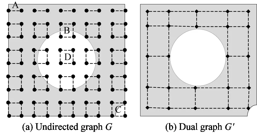
Fig.3 Generation of box
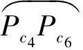
Situation D: The reason for this situation is that the four grids notes are full in a hole on the surface. To solve this problem, the rules shown in Fig.4(d) should be followed. When planning the tool path, this box will be abandoned.
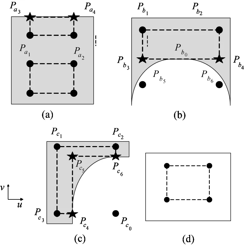
Fig.4 The rules for illegal box
2.2.2 Generation cost and connection cost of box
2.2.2.1 Generation cost of box
The grid notes of box A are {pa1, pa2, pa3, pa4}, and the influence values are Epa1, Epa2, Epa3and Epa4. Generation cost of box A can be defined as
Gencost(A)=Epa1ωa1+Epa2ωa2+Epa3ωa3+Epa4ωa4
(11)
where, ωa1is the weight of pa1, ωa2is the weight of pa2, ωa3is the weight of pa3and ωa4is the weight of pa4.
According to the same value that these four grid notes have, they are treated as having the same significant and ωa1=ωa2=ωa3=ωa4=1. The generation cost of box A can be redefined as
Gencost(A)=Epa1+Epa2+Epa3+Epa4
(12)
2.2.2.2 Connection cost of box
It is very important to ascertain the connection cost of box, which can influence the generation of tool path. There are many factors that can influence the connection of Box, such as the generation cost of box, length cost, cutter-orientation in different boxes, and other factors. The connection cost of box is defined as follows:
(13)
where, ωAis the weight of Gencost(A), ωBis the weight of Gencost(B), LABis the cost of length and its weight is ωL, VABis the cost of tool attitude and its weight is ωV, C is other factors and its weight is ωc.
Because of the uncertainty of C, ωcshould be set like this: ωc=0. Gencost(A), Gencost(B), LABand VABare regarded as the main factors, and they have the same significant: ωA=ωB=ωL=ωV=1. Eq. (13) is redefined as follows:
Bricost(A,B)=Gencost(A)+Gencost(B)+LAB+VAB
(14)
For example, boxes A and B in Fig.5(a). If they are connected together like box A″, which is shown in Fig.5(b), the LABand VABcan be calculated as
(15)
where, e and f are the real lines between box A and B, m and g are the virtual line when A connects with B. VAand VBare cutter-orientations in box A and B.

Fig.5 Connection of box
2.3 Generation of tool path
2.3.1 Preliminary planning of tool path
T-spline surface is a single-curved surface, and its parameter space is also a single-curved surface. If all grid notes can be connected rationally, a unidirectional, unconnected and complex curve will be got, which is considered as the tool path in the parameter space. Based on the connection cost of box, all the costs between each two of boxes can be got, and then a weighted connected graph will be obtained.
BoxBis the matrix of boxes, BoxB={boxij} and 1≤i≤n,1≤j≤m. If there is no box, it is defined like this: boxij=0. BriCis the assemblage of the cost between each two of boxes, BriC={briij} and 1≤i≤n,1≤j≤m. If one of the two boxes is like this: boxij=0, the connection cost is 0. Fig.6(a) is the dual graph G′ of boxes, Fig.6(b) is the undirected graph G of boxes. The triangle area is a non-working area. Considering the principle of MST[10,11], an improved MST is promoted as follows, and a preliminary tool path will be got:

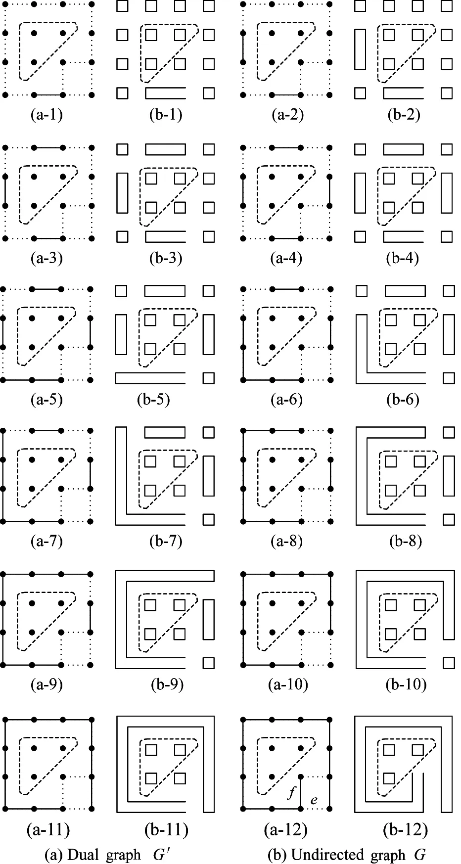
Fig.6 The generation of tool path
2.3.2 Optimization of tool path
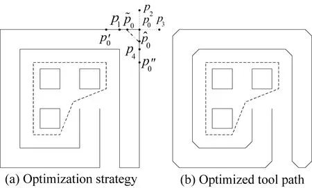
The tool path that is got in 2.3.1 also has a lot of corners, and these corners are right angles. When processing, too many corners will make the tool turn frequently, machine tremble, the life of the tool reduce and the quality of workpiece is affected[12]. In order to solve these problems, an improved chamfering algorithm is proposed. The method is:
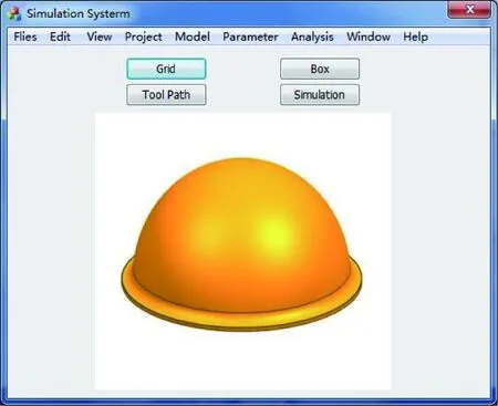
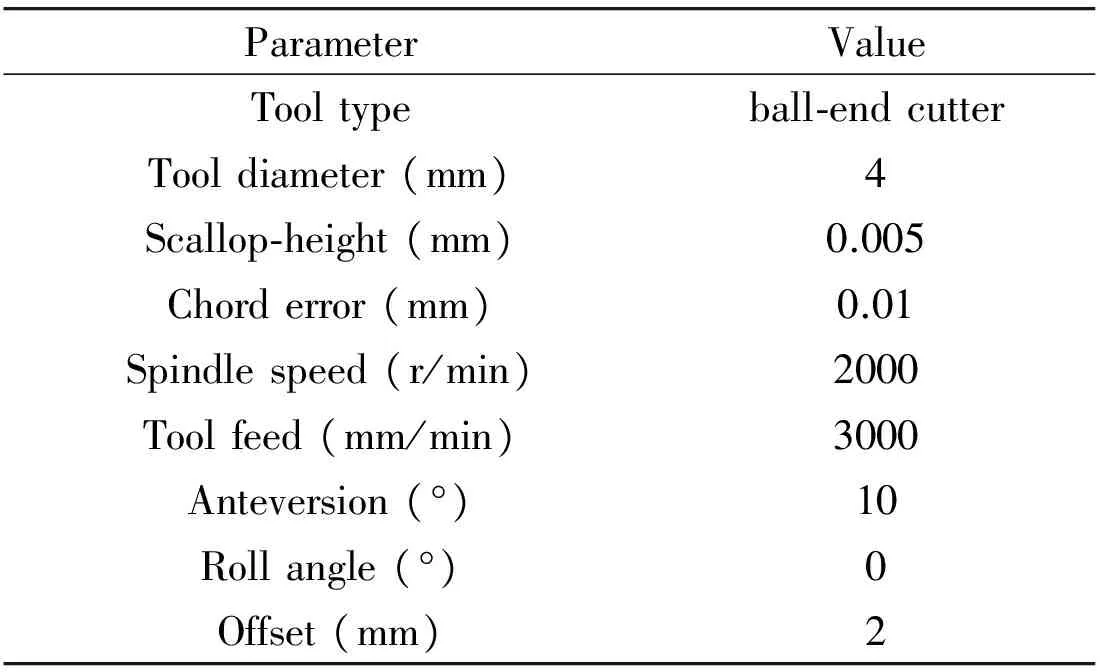
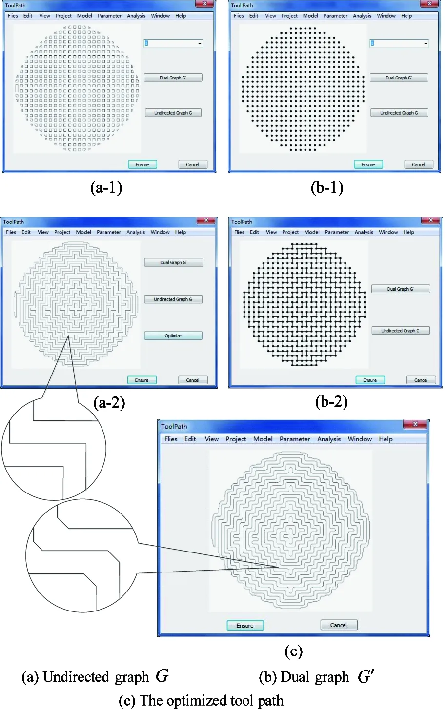
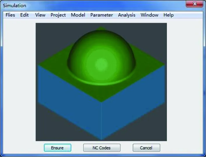
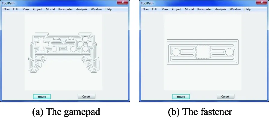
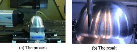
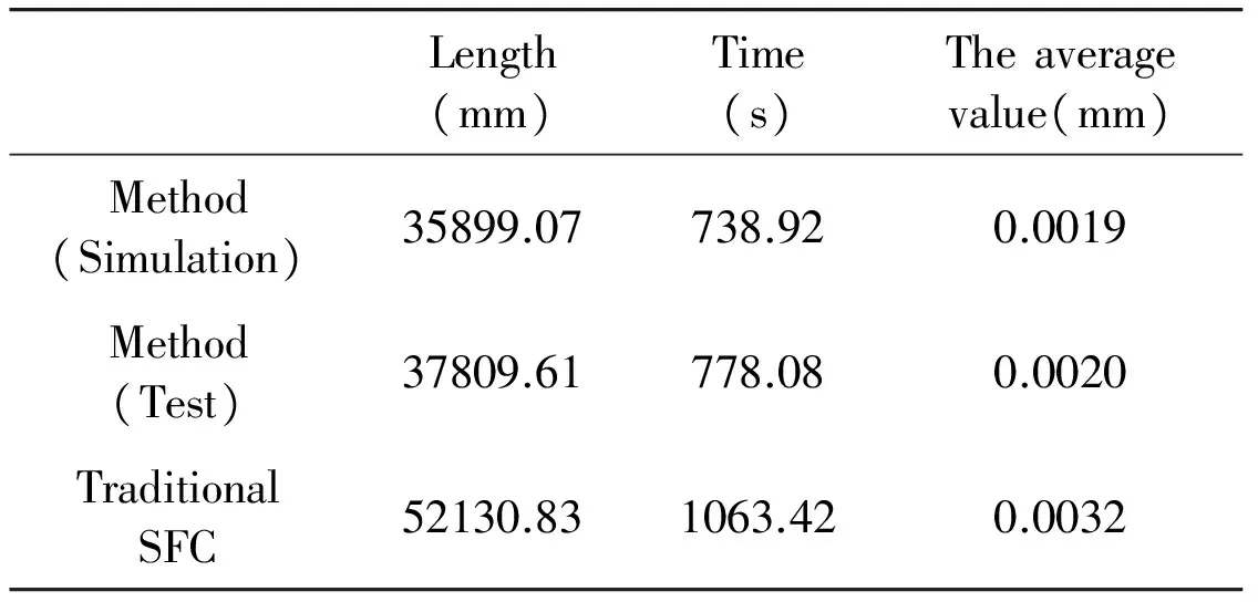
Step 1: The minimum offset distances of u direction and v direction are luand lv. Arbitrary distance d is defined like this: 0 Step 2: As it is shown in Fig.7(a), p0is an arbitrary grid note. Based on d, there are four offset points: p1, p2, p3and p4. According to the coordinates, it is determined whether the four points exist on the tool path. Step 3: Based on the regulation of tool path, there are two of them on the path at most. If there is one offset point on the path, p0will be the start point or termination point. If there are two offset points on the path and they have the same abscissa, such as p1and p3, or they have the same ordinate, such as p2and p4. It means that the path at p0is straight. If they have different abscissas and ordinates, such as p1and p4, meaning that there is a corner at p0. (16) Fig.7 The optimization of tool path At last, mapping the optimized tool path from the parameter space to the Euclidean space, the whole tool path for processing can be obtained. Microsoft Visual Studio 2015 is regarded as a development platform, and Open GL is treated as a graphics engine. A simulation system of NC milling based on space-filling curve is developed to verify the method, which is proposed in this paper. The helmet is regard as the workpiece.After logging in, Files in the menu can help us to import workpiece. And the main operating interface is developed shown in Fig.8. Fig.8 The main operating interface where, after importing the workpiece, it will be shown in the lower part of the surface.Parameter in the menu can help us to set the cutting parameters. When clicking the button: Grid, the grid of workpiece can be checked. When clicking the button: Box, the boxes of workpiece can be shown in the white part. When clicking the button: Tool Path, each step of the tool path of workpiece can be checked. When clicking the button: Simulation, the result of simulation will be shown and the NC codes can be got. After importing the helmet, the cutting parameters are shown in Table 1. Table 1 The cutting parameters where, the anteversion and the roll angle of tool are relative to normal vector. The grid of helmet is generated primarily. Based on the grid and the information of helmet, the boxes are generated shown in Fig.9. Fig.9 The boxes of helmet Based on all of boxes, the tool path is got as these are shown in Fig.10. Fig.10 The tool paths of helmet where, Fig.10(a-1) is the first tool path of helmet, Fig.10(b-1) is the dual graph of the first tool path. Fig.10(a-2) is the whole tool path of helmet, Fig.10(b-2) is the dual graph of the whole tool path. Fig.10(c) is the optimized tool path, which is got by using the improved chamfering algorithm. The tool paths in the annotation of Fig.10(a-2) have many right-angle corners, which are replaced by improved corners, shown in the annotation of Fig.10(c). With the whole tool path having been obtained,the simulation of helmet is shown in Fig.11. At the same time, according to the result of simulation, this system can realize the method that is proposed in this paper. Fig.11 The simulation of helmet By using this simulation system, the tool paths of the gamepad and the fastener are generated, and the results are shown in Fig.12. Fig.12 The tool paths of the gamepad and the fastener where, the areas that consist of the dotted lines are holes. The actual machining experiment is carried out on the VMC850 vertical machining center, and the process of experiment is shown in Fig.13. Fig.13 The actual machining where, as it is shown in Fig.13(a), a laser displacement sensor is used to record the length and the scallop-height of the tool path. A timer also is used to record the time of the tool path. The scallop-heights of 200 random sampling points are gauged, and the average value of these scallop-heights is calculated. The results of experiment and calculation are shown in Table 2. Table 2 The results Table 2 shows that the values of simulation and test with the method, which is proposed in this paper, are similar, and the deviations of these values between simulation and test are less than 10%, which means that this method is feasible and effective.The average value of scallop-height in this method is less than the average value of scallop-height in traditional SFC. And the average value is also less than the scallop-height that was set in the cutting parameters, which means that the method can satisfy the requirement of actual machining. At the same time, compared with the traditional SFC, the length is shorter and the time is less. The tool paths generated by space-filling curve always turn frequently, the length and the generation time of the tool paths are both relatively long. In order to solve these problems, a toolpath generation method of NC milling based on space-filling curve is proposed. First, T-spline surface is regarded as the modeling surface, the grid, which is based on the limited scallop-height, can be got in the parameter space, and the influence value of grid node is determined. Second, the box is defined and planned, and the tool paths which are based on minimal spanning tree are got preliminarily. Finally, based on the improved chamfering algorithm, the whole tool paths are got. A simulation system is developed for computer simulation, and an experiment is carried out to verify the method. The results show that the method can satisfy the requirement of actual machining, and the length and the time of the tool paths are reduced. [ 1] Zhao S T. Research on Tool Path Planning Algorithm for Free-form Surface Machining:[Ph.D dissertation]. Nanjing: Department of Electrical and Mechanical, Nanjing University of Aeronautics and Astronautics, 2011.3-14(In Chinese) [ 2] Liu W. Research on Key Technologies of Point Cloud Numerical Control Tool Path Generation:[Ph.D dissertation]. Nanjing: Department of Electrical and Mechanical, Nanjing University of Aeronautics and Astronautics, 2013.5-17(In Chinese) [ 3] Wen X L, Zhao Y B, Wang D X, et al. Accurate evaluation of free-form surface profile error based on quasi particle swarm optimization algorithm and surface subdivision. Chinese Journal of Mechanical Engineering, 2013, 26(2):406-413 [ 4] Li W J. Research on Algorithms of Tool Path Generation ofComplex Surface Machining Based on the HilbertCurve in Fractal Theory: [Ph.D dissertation]. Nanjing: Department of Electrical and Mechanical, Nanjing University of Aeronautics and Astronautics, 2012. 4-11 (In Chinese) [ 5] Wang A Z, Zhao G. The analysis of T-spline fairness. Computer-Aided Design and Applications, 2013, 10(5):817-825 [ 6] Li X. T-splines and Splines over T-mesh: [Ph.D dissertation]. Hefei: Department of Mathematics, University of Science and Technology of China, 2008. 19-33(In Chinese) [ 7] Li Juli. The Research on method of Automobile Body Point Cloud Surface Reconstruction Technology Based on T splines: [Ph.D dissertation]. Jinan: Department of Mechanical, Shandong University of Technology, 2014. 31-57 (In Chinese) [ 8] Ha S H, Choi K K, Cho S. Numerical method for shape optimization using T-spline based isogeometric method. Structural and Multidisciplinary Optimization, 2010, 42(3):417-428 [ 9] Jia X Y. Intelligent Optimization of T-spline Knot Vector for Surface Fitting:[Ph.D dissertation]. Jinan: Department of Computing, University of Jinan, 2015. 34-54(In Chinese) [10] Wang H Y. Minimal spanning tree algorithm& its application. Inner Mongolia Science technology & Economy, 2011,6:72-73(In Chinese) [11] Buscema M, Sacco P L. MST fitness index and implicit data narratives: a comparative test on alternative unsupervised algorithms.Physica A: Statistical Mechanics and its Applications, 2016, 461: 726-746. 10.1016/j.physa.2016.05.055 [12] Li D X, Jiao J P. Research on tool path generation algorithm and improvement based on Hilbert space-filling curves. China Mechanical Engineering. 2011,22(22):2739-2743(In Chinese) 10.3772/j.issn.1006-6748.2017.04.011 ①Supported by the National Natural Science Foundation of China (No. 51575143). ②To whom correspondence should be addressed. E-mail: xiulinsui@163.com on Oct. 26, 2016 her Ph.D degree in Harbin Engineering University in 2011. She also received her M.S. degree from Harbin University of Science and Technology in 2004 and her B.S. degree from Jilin University of Technology (now is Jilin University) in 1985. She also was a visiting scholar of Technische Universiteit Delft between 2009 and 2010. Her research interests include computer integrated manufacturing technology, virtual manufacturing technology and numerical control technoogy.
3 Experiment
3.1 Computer simulation
3.2 Actual machining
4 Conclusions
 High Technology Letters2017年4期
- High Technology Letters的其它文章
- A novel conditional diagnosability algorithm under the PMC model①
- Novel differential evolution algorithm with spatial evolution rules①
- Temperature field analysis of two rotating and squeezing steel-rubber rollers①
- First order sensitivity analysis of magnetorheological fluid damper based on the output damping force①
- Studies on China graphene research based on the analysis of National Science and Technology Reports①
- Operation of the main steam inlet and outlet interface pipe of a nuclear power station①