
A coupling VWM/CFD/CSD method for rotor airload prediction
2017-11-21 12:53:46ShiYongjieXuYiXuGuohuWeiPeng
CHINESE JOURNAL OF AERONAUTICS 2017年1期
Shi Yongjie,Xu Yi,Xu Guohu,Wei Peng
aNational Laboratory of Science and Technology on Rotorcraft Aerodynamics,Nanjing University of Aeronautics and Astronautics,Nanjing 210016,China
bPre-noncommissioned Officers Training Base,Army Aviation Institute,Beijing 101116,China
A coupling VWM/CFD/CSD method for rotor airload prediction
Shi Yongjiea,*,Xu Yia,Xu Guohuaa,Wei Pengb
aNational Laboratory of Science and Technology on Rotorcraft Aerodynamics,Nanjing University of Aeronautics and Astronautics,Nanjing 210016,China
bPre-noncommissioned Officers Training Base,Army Aviation Institute,Beijing 101116,China
Airload;CFD/CSD coupling;Navier-Stokes equations;Rotor;Viscous wake model
A coupling fluid-structure method with a combination of viscous wake model(VWM),computational fluid dynamics(CFD)and comprehensive structural dynamics(CSD)modules is developed in this paper for rotor unsteady airload prediction.The hybrid VWM/CFD solver is employed to model the nonlinear aerodynamic phenomena and complicated rotor wake dynamics;the moderate deflection beam theory is implemented to predict the blade structural deformation;the loose coupling strategy based on the ‘delt method’is used to couple the fluid and structure solvers.Several cases of Helishape 7A rotor are performed first to investigate the effect of elastic deformation on airloads.Then,two challenging forward flight conditions of UH-60A helicopter rotor are investigated,and the simulated results of wake geometry,chordwise pressure distribution and sectional normal force show excellent agreement with available test data;a comparison with traditional CFD/CSD method is also presented to illustrate the efficiency of the developed method.
1.Introduction
The flow around a helicopter rotor is highly complex and characterized by flow phenomena that include shock waves on the advancing blade,dynamic stall and separated flow at the retreating side,and the mutual interaction of the blades with the returning trailed rotor wake.Additionally,the rotor blade experiences large aeroelastic deflections which make the flow morecomplex.Therefore,modeling thecoupled fluidstructure remains the most challenging task,and is needed to accurately predict the rotor aerodynamic loads.
The traditional comprehensive structural dynamics(CSD)analyses are mostly based on the empirical wake-induced velocity models and lifting line theory.These methods are limited in predicting the complex aerodynamic effects of a rotor with an advanced platform.The modern,Eulerian-based,computational fluid dynamics(CFD)method which models the whole rotor system using a multi-block strategy has the capability to capture the rotor wake structure and all aerodynamic phenomena entirely from first principles.1,2In the past few decades,several notable coupled CFD/CSD methodologies aredeveloped and significant achievements have been achieved in blade airload prediction.3–9
The wake structure is crucial for the rotor performance and blade airload predictions.The numerical dissipation inherent in CFD difference schemes causes the rotor wake to diffuse dramatically.The grid refinement algorithm and high-order schemes are employed to improve the prediction accuracy.Unfortunately,the requirements of computational resourcesand timemay becomecomputationally prohibitive.10Another way to capture the rotor wake is the hybrid CFD approach where the near-body flow-field is solved using the CFD,and the off-body wake is modeled by the external wake model.Recently,some hybrid CFD solvers have been developed,and the results indicate that this method can significantly reduce the computational costs while retaining the similar prediction accuracy.11–15However,limitations still exist regarding the singularity-based vortex module used for wake modeling.Because of the inviscid flow assumption,the wake solutions have to rely on empirical formulations to account for the roll-up rule,initial vortex core size,and vortex decay factor.
The viscous wake model(VWM)which models the complicated rotor wake stretching and viscous diffusion by solving incompressible Navier-Stokes equationsis a promising approach to overcome the shortcomings involved in the singularity-based vortex model.The detailed derivation of VWM and its applications to rotor flow-field simulations are presented in several researches.16–18In the work by Shi et al.19,a hybrid Eulerian-Lagrangian methodology with a combination of CFD and VWM is developed,and the numerical results show a good prediction of the wake evolution and blade airload in the vortex dominated flight condition by comparing with conventional CFD method.Based on these works,an eff icient and accurate fluid-structure analysis,which conquers the numerical problem existing in traditional CFD/CSD method,is proposed for rotor airload and structural load predictions in this paper.The hybrid VWM/CFD approach is employed to capture the complex aerodynamic phenomena,wake structure,and blade airload.The CSD module with a modified beam element is used for rotor trim and structure deflection prediction.The loose coupling strategy is employed to couple the two solutions.Several numerical simulations of Helishape 7A and UH-60A rotors in hover and forward flight conditions were carried out and the results,including wake structure,induced velocity,and blade airloads,were compared with measurements to validate the method.Furthermore,the comparisons between present coupling method and traditional CFD/CSD method are presented in this paper.The numerical results of rotor spanwise normal force show that the airload prediction can be well improved by the developed coupling VWM/CFD/CSD method which meanwhile dramatically reduces the required computational resource,especially in the vortexdominated low-speed flight case.
2.Methodology
2.1.Rotor aerodynamics model
The hybrid VWM/CFD method is employed to model rotor aerodynamics.A schematic is shown in Fig.1.The nearbody flow-field has been solved using the Eulerian-based CFD method and the off-body wake is modeled using the Lagrangian-based VWM.The mathematical and numerical formulation of hybrid VWM/CFD method has been extensively documented in Ref.19.Here,only the essential details are given.
(1)Navier-Stokes solver
The3D unsteady Reynoldsaveraged Navier-Stokes(RANS)equations are employed as the governing equations,which can be written as
where W is the vector of conserved variables,F(W)and G(W)are the convective and viscous flux vectors,respectively.All physical quantities are non-dimensionalized by blade chordcand sound speeda∞,density ρ∞,temperatureT∞,and the coefficient of dynamic viscosity μ∞of free stream.
The inviscid terms are computed using a second-order upwind scheme(Roe scheme)20and the viscous terms are computed using the second order central difference.The dual-time stepping method is applied with the LU-SGS scheme21to simulate the unsteady flow phenomenon at every pseudo-time step.The Spalart-Allmaras turbulence model22is used for the RANS closure.The validation of the RANS code is demonstrated through a wide range of rotorcraft applications23–25,i.e.,single rotor,dual-rotors interaction,and rotor/fuselage interaction.
(2)Viscous wake model
The effect of compressibility is little in the vast region in rotor vortical flow except for a small area around the blade surface.10Therefore,the flow field where the rotor wake rolls up and evolutes can be considered to be incompressible.In this paper,the VWM is used to model the rotor-wake dynamics.The rotor-wake field is discretized into a set of distributed Lagrangian vector-valued particles and can be described by vorticity kinematic and dynamic equations:
where xp(t)is the position of the particle,αpis vector-valued total vorticity inside particle,vis the kinematic viscosity,u(xp,t)=u∞+ui,u∞is the free stream velocity,and uiis the local induced velocity.
The first term on the right-hand side of Eq.(2)is the stretching-effect term,and the velocity gradient can be obtained by analytically differentiating the velocity field using a transposed formulation.The second term is the viscous diffusion term,which can be solved using the particle strength exchange technique.The fast multipole method has been implemented to eliminate the requirement of huge computational time for the direct evaluation of particle convection velocity.The details of the application of VWM to rotor wake simulation are presented in Refs.16–18.
(3)Coupling strategy of hybrid VWM/CFD method
A carefully designed coupling strategy is required to treat information interchange between two solvers.In this study,the ‘integrated vorticity approach”19is adopted to pass the vorticity from the CFD domain to the VWM solution.The circulation strengths are computed using the sectional lift coeff icient integrated from the pressure distributions on the blade surface;the bound vortex strength Γbis then given using the Kutta-Joukowski theorem.As the tip vortex strength is obtained,the vorticity of a newly generated vortex in VWM can be calculated using the following formula:
where γωis the circulation value of the new vortex,and νbis the sectional relative flow field velocity,including free stream velocity and blade motion velocity.
The ‘outer boundary correction” approach19is used to pass the flow-field information from the VWM to the CFD solution.The induced velocity calculated by VWM is imposed on the outer boundary of the blade grid since the compression effect is little in the region far away from the blade surface.The density,energy and pressure,in addition to the wake-induced velocity,are needed to be specified at the outer boundary for a compressible CFD solution.The variables can be obtained from the following equations:
where(u∞,v∞,w∞),(ug,vg,wg)and(ui,vi,wi)are the freestream velocities,blade moving velocities and wake induced velocities respectively,γ is ratio of specific heats,andais the local sound speed.
2.2.Rotor structural dynamics model
The rotor computational structural dynamics(CSD)method is comprised of a nonlinear 1D beam model with the moderate deflection and a linear 2D cross-section model.Based on the Hamilton principle,the governing equation of energy conservation for the beam can be expressed as follows:
whereSandTare the strain energy and kinematic energy,respectively,andWeis the work of external loads including aerodynamic forces and moments of the blade.
The original beam element was 23 degree of freedoms(DOFs),and sectional constants were obtained based on the Saint Venant solution.To utilize the sophisticated crosssectional characteristics obtained form VABS software,Friedmann et al.26modified the original model.Based on these formulations,a modified 14 DOFs beam element is developed.9As shown in Fig.2,each beam element consists of two end nodes and one internal node.Each end node has 6 DOFs:axial displacementu,transverse deflectionsv,wand their radial derivatives,and torsional elastic deformation,while the internal node has only 2 DOFs.The strain energy,kinematic energy,and work of external loads on theith element can be derived from its degrees of freedom.The generalized displacements can be assumed as
where {Φv},{Φw},{Φφ} and {Φu} are space-dependent interpolation functions; {V}, {W}, {Φ} and {U} are timedependent nodal parameters of each generalized displacement.Hermite interpolation polynomials are employed in spacedependent interpolation functions.The finite-element equations of motion for theith element are given by
where Miis the mass matrix,Cithe damping matrix,Kithe stiffness matrix,and Fithe load vector.All the motion equations of each ith element are assembled,and then the nodal generalized displacement vector q is solved.
2.3.Coupling VWM/CFD/CSD method
The loose coupling which interchanges the structural deformations and airloads between fluid and structure solutions per revolution is mostly used in the traditional CFD/CSD simulation.The efficiency and validation of the rotor application have been demonstrated by several researchers.In this study,the loose coupling strategy based on the ’delt method’is also adopted.Fig.3 shows the flowchart of the coupling method.The solution is carried out in the following steps:(A)initialize the CSD,CFD,and VWM modules according to flight conditions and rotor fundamental parameters;(B)perform the CSD module to converge and obtain the blade air-loads and elastic deformation;(C)pass the blade deformation and trimmed control inputs to the fluid solution.Because of the large time step used in the CSD module,the FFT interpolation technique is employed in the solution to obtain the deformations at every CFD step;(D)perform the VWM/CFD module in a tight coupling way;(E)couple the obtained blade airloads back to the CSD module;(F)repeat steps(B)–(E)until the deformation,airloads,and trims are converged.
The rotor rigid-body motions such as rotation and control pitches can be modeled easily using the Euler transformation;however,a robust and efficient grid deformation algorithm is required to account for the blade deflection for fluidstructure simulation.In this study,an algebraic grid algorithm9is employed.The structural deformations from CSD module are specified as a function of radius and azimuth at the quarter chord of the blade.The grid deformation at any section consists of two parts:rotation term and translation term.Then,the grid coordinates after deformation can be given by the following equation:
where(xd,yd,zd)and(x,y,z)are the deformed and original blade grid coordinates respectively.The rotation matrix T is determined by the radial derivatives of flap and lag degrees and elastic torsional deformation,and dlinrepresents the translation deflections in axial,lag,and flap directions.Fig.4 shows the deformation of body-fitted blade grid.
3.Results and discussion
The numerical cases of two rotors are performed to validate the developed method.In Section 3.1,the Helishape 7A rotor is used to investigate the effect of elastic deformation on blade airloads.In the following sections,the detailed investigation into the coupling VWM/CFD/CSD method has been performed with a UH-60A rotor.
3.1.Helishape 7A rotor
The four-bladed 7A rotor27is articulated with a radiusR=2.1 m,aspect ratio of 15,and solidity σ=0.0849.The platform of the 7A rotor is plotted in Fig.5.The test data regarding blade normal force,chordwise pressure and rotor performance were widely presented in literatures;however,the structural properties were unpublished.Therefore,the assumed structural properties are used in this paper to match the blade torsional deformation obtained from experiment27in hover condition.The flapping,lag and pitch hinges are located at the radial stationsr=0.0357R,0.0362Rand 0.0743R,respectively.
Fig.6 shows the grid system used for 7A rotor simulation.The overset grid system contains a large-scale background mesh and four body-fitted C-O grids for each blade.The background mesh has a dimension of 315×134×207 and the blade grid has a dimension of 189×31×71.
First, a low-speed descending flight withMatip=0.617,μ =0.167 is performed to demonstrate the capability of rotor wake simulation for two CFD methods.Fig.7(a)shows the wake structure captured by hybrid VWM/CFD method.Thecomputationalparametersof VWM are set as the overlap factorcε=1.3,wake cut-off distanceRcut=3R,and minimum vortex sizehres=0.03R.About 21586 vortex elements were generated.The wake plotted in terms of vorticity iso-surface and the non-dimensional vorticity magnitude is set as|ω|=0.4.The formation and rollup of the rotor tip vortex on the advancing and retreating sides are observed.Approximately seven revolutions of the rotor tip vortex were captured,which is sufficient for rotor airloads and performance predictions.The wake structure plotted with a non-dimensional vorticity magnitude of|ω|=0.05 by using traditional CFD method is shown in Fig.7(b).The significant numerical diffusion arising from numerical difference and the non-continuous interpolation among multi-blocks existed in the wake-developing zone,and caused the rotor tip vortex to diffuse rapidly.
In this low-speed flight case,the rotor exhibits strong blade-vortex interaction(BVI)phenomena.Fig.8 shows the predictionsofBVIevents.Because ofthe wellpreserved rotor vortex in the hybrid method,the multiple BVI events occurred at the outer board of blade at 90°and 270°.By contrast,only weak orthogonal BVI events are captured by the traditional CFD method.Fig.9 shows the density contour slices at three spanwise stations at 90°:r/R=0.600,0.800 and 0.950.The non-dimensional density in undisturbed free stream is 1.As shown,the density changes significantly in small area around the blade,whereas in the vast area about one chord away from blade surface,the changes of density are small.It means that the effect of compressibility is little in this area.
Then,we investigate the effect of elastic deformation on blade airloads with three numerical examples of the 7A rotor.The first two cases refer to the unique hover flight of the helicopter.Fig.10 plots the elastic deformations at cases ofMatip=0.617 and collective pitches θ0=5.97°,8.94°.In hover flight,the flap deformation(dimensionalized by the radiusR)as well as its induced angle of attack oscillation remains constant during one revolution,and has little effect on blade airloads, whereas the torsional deformation alters the distribution of the sectional,thereby changing the blade airloads.As shown in Fig.10,both the flap and torsional deformations are small.The angle of attack oscillation reaches approximately 0.5°at the blade tip where the maximum deformation occurs.
Fig.11 shows the comparison of the sectional thrust coeff icientCTbetween the rigid and elastic rotor models.Because of the small torsional deformation,the airloads predicted using the rigid rotor model are almost the same as those from the elastic rotor model.The results indicate that the elastic deformation has a minor effect on airload prediction for the hover rotor.
Thethird caseisa high-speed forward flightwithMatip=0.656,μ =0.4.The control inputs used in the calculation are from the experiment.27In forward flight,the up and down motions of blade flap have an effect on the perpendicular component of sectional relative velocity and result in the change of sectional angle of attack.Fig.12(a)shows the time history of the rigid displacement and elastic deformation of flap motion.As shown,the rigid displacement is the main component of blade flap motion and contributes more to the airloads than elastic deformation.Fig.12(b)shows the time history of torsional deformation at the blade tip.Being different from the hover case,the torsional deformation varies with azimuthal angle Ψ.The blade tip undergoes significant forces and pitching moments,thereby showing large torsional deformation at the advancing side,whereas the elastic deformation is relatively small at the retreating side.
Fig.13 shows the comparison of the normal forceCnwith measurement.27,28In the rigid rotor model,the sectional attack-angle fluctuation which arose from structural deformation is not considered so that the airloads exhibit a large dis-crepancy at the rotor advancing side where the torsional deformation is serious.The normal force is significantly improved by using the elastic rotor model.However,there is still large discrepancy shown atr/R=0.915 for azimuthal locations in the range 0–180°.It may be caused by the assumed structural properties used in calculation.The blade undergoes serious elastic deformation at rotor advancing side in high speed flight.Therefore,the accuracy of airload prediction depends on structural deformation estimation to a large extent.In order to further illustrate the issue,the time history of normal force coefficientCnsimulated with conventional CFD/CSD method by Altmikus28is given in Fig.13(b).Similarly,the predicted results also exhibit apparent discrepancies at 0–180°.In addition,the comparison between the loose coupling and tight coupling is investigated in their research and shown in this figure.Almost similar results mean that there is little difference between the two coupling algorithms for rotor airload prediction.
Fig.14,the detailed chordwise pressure coefficientCpdistributions at two azimuthal locations atr/R=0.915,also presents the apparent difference between the elastic and rigid models at 120°.The above results indicate that the elastic model is necessary for accurate prediction of the blade airloads in forward fligh.
3.2.UH-60A rotor
Two numerical examples of the UH-60A rotor are carried out in this section to validate the developed VWM/CFD/CSD method.The fully articulated four-bladed UH-60A rotor29has a radius of 8.178 m and a solidity of 0.0832.Fig.15 illustrates the platform of UH-60A rotor.
The C-H blade grid with a dimension of 191×30×70 is used for all numerical examples.For comparison purposes,the same results predicted using CFD/CSD with overset grid are also presented.The grid system shown in Fig.16 is comprised of a large-scale background mesh and four body-fitted grids for each blade.The background mesh has a dimension of 310×135×210.The computational parameters of VWM are set asCcut=3,cε=1.3 andhres=0.03R.
(1)Low-speed flight condition(C8513)
The first case refers to a low-speed forward flight withCT/σ=0.076,μ=0.153 andMatip=0.638.The rotor is trimmed in solution to match the desired thrust coefficient and flap motion.Table 1 lists the trimmed control inputs obtained from two solutions.θ0,θ1cand θ1srepresent collective,lateral and longitudinal pitch respectively.
In low-speed flight,the slowly moving rotor wake retains in the vicinity of disk plane and plays an important role in rotor performance.Fig.17 plots the predicted rotor wake structure in terms ofvorticity iso-surface.The value ofnondimensional vorticity magnitude is|ω|=0.2.As shown,the traditional CFD/CSD method captures less than one revolution of rotor wake due to significant numerical diffusion.By contrast,the VWM/CFD/CSD method preserves several revolutions of concentrated tip vortex and provides the adequate solution of rotor wake for airload prediction.
Fig.18 shows the comparison of the computed sectional normal force with test data30at four radial stations.The airloads from the two methods both correlate well with test data at the front part of the rotor(90°–180°–270°),while a large discrepancy occurs at the rear part(270°–360°–90°).It may be affected by the in fluence of the wake shape.The strong super vortex forming at two sides of rotor has more effect on blade airloads at the rear part of the rotor than the front part.The improved prediction of blade airloads at the first quadrant using the VWM/CFD/CSD method also indicates that the accuracy of the rotor wake is a major factor contributing to airload prediction during low-speed forward flight.
Table 2 summarizes the requirement of computational time for the two solutions.All sample calculations were performed on a workstation(Core8 E7200 2.6 G).As shown,a typical unsteady solution requires approximately 45 h and 7 h for traditional CFD/CSD and VWM/CFD/CSD methods,respectively.The results indicate that the developed method could dramatically reduce thecomputationaltime forairload prediction.
(2)High-speed flight condition(C8534)
The high-speed flight case withCT/σ=0.084,μ=0.368 andMatip=0.642 is also investigated.Different from the vortex-dominated flow field of the low-speed flight,the rotor blades experience strong transonic flow and separated flow during high-speed flight.On the advancing side,a strong shock wave occurs at the outer board of the blade where the maximum blade tip Mach number reaches 0.878.In addition,the high attack angles are required at the retreating side to maintain the rotor lateral balance which results in dynamic stall.Table 3 lists the trimmed control inputs.The collective and cyclic pitches agree well with the test data.
Fig.19 plots the predicted rotor wake structure.The tip vortex moves downstream rapidly when it releases from the blade.The CFD/CSD method captures only one-fourth of the revolution of the rotor wake compared to that of the low-speed flight.It means that a more large-scale and highdensity grid is needed for traditional CFD/CSD simulation in high-speed flight.By contrast,theLagrangian-based VWM is independent of the flight case and full wake structure is preserved by using it.
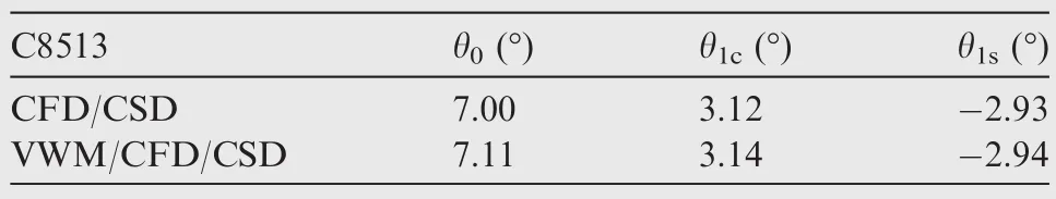
Table 1 Trimmed control inputs of C8513 case.
Fig.20 shows the comparison of the computed sectional normal force with the test data31at four radial stations.The blade undergoes large elastic deformation in this high thrust case.Overall,the magnitude and phase of airloads from VWM/CFD/CSD method are in better agreement with the measured data.However,airload at the inboard sections is better captured by CFD/CSD method in the range 210–360°in spite of the wake diffusion.The discrepancy may arise from wake modeling.In present study, ‘one strong tip vortex model”is used in VWM and it works well under most flight conditions,whereas more than one vortex may form along blade span at retreating side(around 270°)in high-speed flight due to the effect of alternatively positive and negative variations of spanwise lift distribution caused by separated and reverse flow.A ‘multi-trailer vortex model” should be employed in the modeling of wake formation to account for the effects of multiple vortices.In high-speed flight,the rotor experiences complex aerodynamic phenomena regarding shock wave,dynamic stall,separated and reverse flow as well as large elastic deformation during one revolution.Therefore,more accurate nonlinear aerodynamic and structure models are both required to improve the airload predictions.
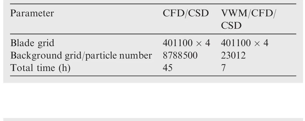
Table 2 Comparison of computational time between two solutions.
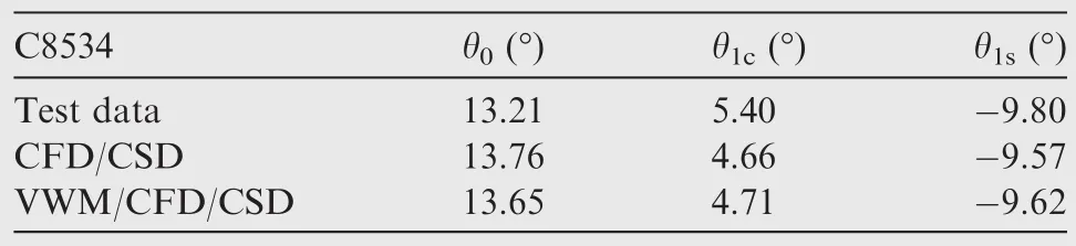
Table 3 Trimmed control inputs of C8534 case.
Finally,the comparison of pitching moment between calculation and test data is shown in Fig.21.The mean values are removed because of inaccurate measurement.31The torsional deformation is dependent on the sectional pitching moment.As shown,the calculated pitching momentsCmfrom two solutions exhibit a subtle difference which indicates that the discrepancy shown in Fig.20 mainly arises from structure deformation rather than rotor wake.
4.Conclusions
(1)The numerical results of rotor wake geometry,sectional normal force,and pitching moment in several representative conditions are presented.Excellent agreement with available experimental data demonstrates the capability of the coupling VWM/CFD/CSD method for application to rotors.The developed method could dramatically reduce the computational time.For a forward-flight case,the computation time is approximately one-sixth ofthe conventionalCFD/CSD method.
(2)Due to significant numerical diffusion which arose from difference scheme and non-continuous interpolation,high density grids as well as huge computational resources are required in traditional CFD simulation to achieve adequate resolution of rotor wake which is crucial for the blade airload prediction.By contrast,the hybrid CFD method has the capability to preserve the concentrated rotor vorticity structure for a long time by using VWM.
(3)The up and down motion of the blade flap changes the perpendicular component of sectional velocity and attack angle;however,the elastic flapping deformation is much smaller than the rigid displacement.The torsional deformation is the major factor that affects the airload prediction in forward flight.In hover flight,both elastic flapping and torsional deformation are small,and thereby have minor effect on blade airloads.
(4)In the vortex-dominated low-speed forward flight,the rotor wake structure plays an important role in airload prediction;in high-speed flight,the blade undergoes large elastic deformation and involves transonic flow field and dynamic stall during rotation,and thereby more accurate nonlinear aerodynamic and structure models are both required to improve the airload prediction.
Acknowledgements
This work was supported by the National Natural Science Foundation of China(No.11302103).
1.Strawn RC,Caradonna FX,Duque EPN.30 years rotorcraft computational fluid dynamics research and development.J Am Helicopter Soc2006;51(1):5–21.
2.Datta A,Nixon M.Review of rotor loads prediction with the emergence of rotorcraft CFD.J Am Helicopter Soc2007;52(4):287–317.
3.Potsdam M,Yeo H,Johnson W.Rotor airloads prediction using loose aerodynamic/structural coupling.J Aircr2006;43(3):732–42.
4.Datta A,Sitaraman J,Chopra I.CFD/CSD prediction of rotor vibratory loads in high-speed flight.J Aircr2006;43(6):1698–709.
5.Saito S,Tanabe Y,Hashimoto A,Nakamura Y,Choongmo Y,Aoyama T.Aeroelastic simulation of HART II model using moving overlapped grid approach.Proceedings of the 32nd European rotorcraft forum;2006.
6.Jae-Sang P,Young-Hyun Y,Jeong HS,Soo HP,Sung NJ.Extensive validation of CFD/CSD aeroelastic simulations for a helicopter in descending flight.Proceedings of the American Helicopter Society 43rd annual forum.Alexandria:The AHS International,Inc.;2012.
7.Abras JN,Lynch CE,Smith MJ.Computational fluid dynamics–computational structural dynamics rotor coupling using an unstructured Reynolds-averaged Navier-Stokes methodology.J Am Helicopter Soc2012;57(1):1–14.
8.Bhagwat MJ,Ormiston RA,Saberi HA,Xin H.Application of computational fluid dynamics/computational structural dynamics coupling for analysis of rotorcraft airloads and blade loads in maneuvering flight.J Am Helicopter Soc2012;57(3),032007-1-21.
9.Xiao Y,Xu GH,Shi YJ.Aeroelastic analysis of helicopter rotors using computational fluid dynamics/comprehensive analysis loose coupling model.J Aerosp Eng2015;229(4):621–30.
10.Komerath NM,Smith MJ,Tung C.A review of rotor wake physics and modeling.J Am Helicopter Soc2011;56(2):220061.
11.Wie SY,Im DK,Kwon JH,Lee DJ.Numerical simulation of rotor using coupled computational fluid dynamics and free wake.J Aircr2010;47(4):1167–77.
12.Bhagwat MJ,Moulton MA,Caradonna FX.Development of a CFD-based hover performance prediction tool for engineering analysis.J Am Helicopter Soc2007;52(3):175–88.
13.Yang Z,Sankar LN,Smith MJ.Recent improvements to a hybrid method for rotors in forward flight.J Aircr2002;39(5):804–12.
14.Ye L,Zhang Y,Yang S,Zhu XL,Dong J.Numerical simulation of aerodynamic interaction for a tilt rotor aircraft in helicopter mode.Chin J Aeronaut2016;29(4):843–54.
15.Shi YJ,Zhao QJ,Fan F.A new single-blade based hybrid CFD method for hovering and forward-flight rotor computation.Chin J Aeronaut2011;24(2):127–35.
16.Zhao JG,He CJ.A viscous vortex particle model for rotor wake and interference analysis.J Am Helicopter Soc2010;55(1):1–14.
17.Tan JF,Wang HH.Simulation unsteady aerodynamics of helicopter rotor with panel/viscous vortex particle method.Aerosp Sci Technol2013;30:255–68.
18.Wei P,Shi YJ,Xu GH,Zhao QJ.Numerical method for simulating rotor flow field based upon viscous vortex model.Acta Aeronaut Astronaut Sin2012;33(5):771–80[Chinese].
19.Shi YJ,Xu GH,Wei P.Rotor wake and flow analysis using coupling Eulerian-Lagrangian method.Eng Appl Comp Fluid2016;10(1):386–404.
20.Roe PL.Approximate Riemann solvers,parameter vectors,and difference schemes.J Comput Phys1981;43(2):357–72.
21.YoonS,JamesonA.Lower-upperSymmetric-Gauss–Seidel method for the Euler and Navier-Stokes equations.AIAA J1988;26(9):1025–6.
22.Spalart PR,Allmaras SR.An one-equation turbulence model for aerodynamic flows.Reston:AIAA;1992,Report No.:AIAA-1992-0439.
23.Li P,Zhao QJ,Zhu QX.CFD calculations on the unsteady aerodynamic characteristic of a tilt-rotor in a conversion mode.Chin J Aeronaut2015;28(6):1593–605.
24.Zhao QJ,Xu GH,Zhao JG.Numerical simulations of the unsteady flowfield of helicopter rotors on moving embedded grids.Aerosp Sci Technol2005;9(2):117–24.
25.Wang B,Zhao QJ,Xu GH,Ye L.Numerical analysis on noise of rotor with new type blade-tips based on CFD/Kirchhoff method.Chin J Aeronaut2013;26(3):572–82.
26.Friedmann PP,Glaz B,Palacios R.A moderate deflection composite helicopter rotor blade model with an improved crosssectional analysis.Int J Solids Struct2009;46(10):2186–200.
27.Biava M,Bindolino G,Vigevano L.Single blade computations of helicopter rotors in forward flight.Reston:AIAA;2003,Report No.:AIAA-2003-0052.
28.Altmikus ARM,Wagner S,Beaumier P,Servera G.A comparison:weak versus strong modular coupling for trimmed aeroelastic rotor simulationsProceedings of the American Helicopter Society 58th annual forum.Alexandria:The AHS International,Inc.;2002.
29.Jon DS.Predesign study for a modern 4-bladed rotor for the RSRA.Washington,D.C.:NASA;1981,Report No.:NASA CR-166155.
30.Kufeld RM,Balough DL,Cross JL,Studebaker KF,Jennison WG,Bousman WG.Flight testing of the UH-60A airloads aircraft.Proceedings of the American Helicopter Society 50th annual forum.Alexandria:The AHS International,Inc.;1994.
31.Kufeld RM,Bousman WG.UH-60A air-loads program azimuth reference correction.J Am Helicopter Soc2005;50(2):211–3.
15 April 2016;revised 16 May 2016;accepted 8 August 2016
Available online 22 December 2016
Ⓒ2016 Chinese Society of Aeronautics and Astronautics.Production and hosting by Elsevier Ltd.This is anopenaccessarticleundertheCCBY-NC-NDlicense(http://creativecommons.org/licenses/by-nc-nd/4.0/).
*Corresponding author.
E-mail address:shiyongjie@nuaa.edu.cn(Y.Shi).
Peer review under responsibility of Editorial Committee of CJA.
 CHINESE JOURNAL OF AERONAUTICS2017年1期
- CHINESE JOURNAL OF AERONAUTICS的其它文章
- Anti-plane problem of four edge cracks emanating from a square hole in piezoelectric solids
- Stress analysis and damage evolution in individual plies of notched composite laminates subjected to in-plane loads
- Drilling load modeling and validation based on the filling rate of auger flute in planetary sampling
- An adaptive attitude algorithm based on a current statistical model for maneuvering acceleration
- Spacecraft attitude maneuver control using two parallel mounted 3-DOF spherical actuators
- Angular velocity determination of spinning solar sails using only a sun sensor