
Developing an engineering-statistical model for estimating aerodynamic coefficients of helicopter fuselage
2017-11-21 12:53:40HosseinSheikhiAbasSaghaie
CHINESE JOURNAL OF AERONAUTICS 2017年1期
Hossein Sheikhi,Abas Saghaie
Department of Industrial Engineering,Science and Research Branch,Islamic Azad University,Tehran,Iran
Developing an engineering-statistical model for estimating aerodynamic coefficients of helicopter fuselage
Hossein Sheikhi,Abas Saghaie*
Department of Industrial Engineering,Science and Research Branch,Islamic Azad University,Tehran,Iran
Aerodynamic coefficients;Computational fluid dynamics(CFD);Engineering-statistical model;Helicopter fuselage;Wind tunnel test
The design of the geometric shape of a helicopter fuselage poses a serious challenge for designers.The most important parameter in determining the shape of the helicopter fuselage is its aerodynamic coefficients.These coefficients are determined using two methods:wind tunnel test and computational fluid dynamics(CFD)simulation.The first method is expensive,time-consuming and limited.In addition,estimates in regions away from data can be poor.The second method,due to the limitations of numerical solution,the number of nodes and the used solution,is often inaccurate.In this paper,with the aim of accelerating the design process and achieving results with reasonable engineering accuracy,an engineering-statistical model which is useful for estimating the aerodynamic coefficients was developed,which mitigated the drawbacks of these two methods.First,by combining CFD simulation and regression techniques,an engineering model was presented for the estimation of aerodynamic coefficients.Then,by using the data from a wind tunnel test and implementation of statistical adjustment,the engineering model was modified and an engineering-statistical model was obtained.By spending less time and cost,the final model provided the aerodynamic coefficients of a helicopter fuselage at the desired angles of attack with reasonable accuracy.Finally,three numerical examples were provided to illustrate the application of the proposed model.Comparative results demonstrate the effectiveness of the engineering-statistical model in estimating the aerodynamic coefficients of a helicopter fuselage.
1.Introduction
Models which describe the performance of a physical process are essential for prediction,process control and optimization.1–3In general,two approaches exist for the development of these models.The first approach involves the development of models based on engineering/physical laws governing the process,which includes analytical models and numerical simu-lation.4–7These kinds of models are called engineering models.1,8The other development approach involves the postulation of statistical models and their estimation on the basis of generated data from physical experiments.9These models are known as statistical models.1,2
Both modeling approaches possess some shortcomings and limitations.1,2,8Predictions derived from the engineering models are often not accurate due to some assumptions in modeling,1,8limitations in numerical solution,number of nodes and used solution method.10,11Statistical models can provide good predictions at points close to the observed data,however,in an attempt to carry out predictions in regions away from the data,the predictions are usually poor.Moreover,the preparation of experimental data required to estimate the statistical models is costly and time consuming.1,8,10–12Some researchers began to study various methods in order to discover models by combining engineering models with statistical models,which are useful in adjusting the shortcomings and limitations of the aforementioned models.1,2,8,13–16These models are called engineering-statistical models.1Engineering-statistical models are expected to provide more realistic predictions than the engineering models,and they are less expensive to estimate than the statistical models.1,2
In helicopters,one important characteristic of quality is the shape of the fuselage.The shape of the fuselage is impressive on flight endurance,cruise speed,stability and controllability,altitude,fuel consumption,maneuverability,etc.One of the technical characteristics which determines the suitability of the shape of the fuselage is its aerodynamic coefficients,which is achieved based on macroscopic fluid flow analysis around the helicopter,using Newton’s laws of motion and the basic principles of the laws of conservation of mass,momentum,energy and chemical species.17Based on the nature of the problem and the desired parameters,these basic concepts can be described as algebraic,differential or integral equations.17,18With regards to a body with complex geometric shape,such as helicopter fuselage,there is no exact solution to these equations,and physical experiments(wind tunnel tests)or numerical simulation techniques(computational fluid dynamics)are used to obtain these coefficients.12,19–22
Both wind tunnel test and CFD methods used in the analysis of fluid flow around helicopters have shortcomings and limitations expressed in engineering and statistical models.Themain objective ofthisstudy isto constructan engineering-statistical model in order to accelerate the design process,thereby achieving results with appropriate engineering precision and cost reduction in computing the aerodynamic coefficients of helicopter fuselage which are:the drag coeff icientCD,lift coefficientCLand pitching moment coefficientCm.The engineering-statistical model is far more superior to the statistical model and engineering model because it behaves like the engineering model and has values those are close to the data.1
Therefore,by firstly using the CFD technique to model different well known helicopter fuselage in medium and intermediate weights,including the Bell 412,Bell 212,Bell 214,Bell 205,Agusta A109,Dauphin SA365N and UH-60(here,for the ease of reference,they are called F1,F2,F3,F4,F5,F6,and F7,respectively),with the aid of a Fluent software,and running it,the aerodynamic coefficients of a helicopter fuselage are obtained for a number of angles of attack.Therefore,the trend of changes in these coefficients can be understood in terms of angle of attack of a helicopter.Since the observed trends are nonlinear,by using nonlinear regression,a function obtains fitting on the data.At this stage,an engineering model is achieved which estimates the aerodynamic coefficients of helicopters of medium and intermediate weights at the desired angles of attack.To achieve the considered engineeringstatistical model,a modified version of the sequential model building strategy of Joseph and Melkote1was applied(the JM method).The JM method provides a sequential model building strategy,which helps to identify a prediction model that introduces minimal changes to the engineering model.This prevents additional adjustments which could cause the formation of a model that differs from the concept of the physical phenomena.1Lack of a validation process is a shortcoming of the JM method.Hence,the modified version of the JM method is proposed.Therefore,the resultant model will be one which overcomes the shortcomings and limitations of wind tunnel test and CFD methods,and which can also estimate the aerodynamic coefficients with reasonable engineering accuracy.
The rest of this paper is organized as follows.Section 2 presents the data of various helicopter fuselage modeling in Fluent software and engineering modeling method for estimation of the aerodynamic coefficients.In Section 3,the strategy of sequential engineering-statistical model building of Joseph and Melkote1is introduced and a validation method of the model is proposed.Section 4 presents three numerical examples to demonstrate the application of the proposed models and the effectiveness of engineering-statistical model in estimating the aerodynamic coefficients of a helicopter fuselage.The conclusions and directions of future work are provided in tion 5.
2.Engineering model develop by combining CFD simulation and regression techniques
The modern helicopter industry requires design tools which are able to accurately and efficiently predict aerodynamic flow.10,18In recent years,CFD methods have been increasingly used in the design and analysis of helicopters.This tendency was made by advances in CFD algorithms and the access to more powerful affordable computers.CFD is a virtual simulation technique.A flow can be fully simulated using CFD.12
In this paper,at the first step,by CFD technique,helicopters fuselage of F1,F2,F3,F4,F5,F6 and F7(Fig.1),were modeled by Fluent 6.3 software.Simulations were implemented in 3D and steady state,using implicit second order method,density based turbulent flow((with adaptation model)K-ω shear stress transport(SST)),the ideal gas model,the Sutherland viscous model,at Mach numberMa=0.2 and thenumberofmeshesfordifferentanglesofattack α=3.70×10⁶to 5.43×10⁶.
The software output values for aerodynamic coefficients ofCD,CLandCmare presented in Fig.2.As shown in the figure,aerodynamic coefficients in terms of angle of attack,show nonlinear behavior and this trend is similar in almost all helicopters.Fitting a function to a particular data requires a parametric model that relates the response data to the predictor data with one or more coefficients.The result of the fitting process is an estimate of the model coefficients.23Through trial and error,and also through the survey of various nonlinear regression models,the best fit to the data is achieved for the Fourier model(Model 1)and fifth-order polynomial model(Model 2),respectively.Hence,each of the Models 1 and 2 can be fitted on the CFD data in order to obtain the engineering model of aerodynamic coefficientsCD,CLandCm.

The summed square of residuals is given by
wherenis the number of data points included in the fit andSis the sum of squares error estimate.Because the least-squares fitting process minimizes the summed square of the residuals,the coefficients are determined by differentiatingSwith respect to each parameter,and setting the result equal to zero.23
Nonlinear models are more difficult to fit than linear models because it is impossible to estimate their coefficients using simple matrix techniques.Instead,an iterative approach is required which involves these steps:(A)start with an initial estimate for each coefficient.For some nonlinear models,a heuristic approach is provided which produces reasonable starting values.For other models,random values on the interval[0,1]are provided;(B)produce the fitted curve for the current set of coefficients.The fitted response value^fis given by
and involves calculation of the Jacobian off(α,b),which is defined as a matrix of partial derivatives taken with respect to the coefficients;(C)adjust the coefficients and determine whether the fit is improved,the direction and magnitude of the adjustment depends on the fitting algorithm such as Trust-region and Levenberg–Marquardt algorithms;(D)iterate the process by returning to step 2,until the fit reaches the specified convergence criteria.23
In Fig.3,Fourier model is fitted on CFD data of the mentioned helicopters,and the general engineering model of aerodynamic coefficients of a helicopter with 95%prediction bounds is also shown.In order to obtain specific engineering model for each helicopter,the proposed regression functions should be fitted on the same CFD data,which results in a higher accuracy of the estimates concerning the considered helicopter.
Due to the aforementioned issues,the following general engineering models are suggested for estimating the aerodynamic coefficients of a helicopter fuselage of medium and intermediate weights.
3.Engineering-statistical model building strategy and validation method
The engineering models presented in Section 2 are perfect tools for quick estimation of the aerodynamic coefficients of a helicopter fuselage in arbitrary angles of attack.One of the downsides of engineering models is that the model predictions may not be accurate enough when compared with data from wind tunnel test.1,8Strategies to improve the models generally fall into two categories:(A)model refinement and(B)model updating.2,14,16
Model refinement involves changing the physical principles in modeling or the use of other means in the construction of a model.It is more sophisticated and better represents the physics of the problem.Model updating utilizes mathematical concepts,such as calibration parameters and bias correction of model to match predictions of the model with physical observations.Although model refinement is desirable to improve the predictive capability,however,its strategy is often restricted by the available knowledge and computing resources.In contrast,model updating is a cheaper means which can be practical and useful when carried out correctly.Several model updating strategies have already been proposed in literature.1,2,14,16
In this paper,the modified version of the JM method(Fig.4)was used to update the engineering models of aerodynamic coefficients of a helicopter fuselage.The advantage of this method when compared with other methods is that,it has minimal changes related to the engineering model,and it prevents the additional adjustments which could lead to a model that differs from the concept of physical phenomena.1
One of the flaws of the JM method is the lack of a validation process in the modeling strategy.Therefore,in order to determine the interpolation and extrapolation capability of the model and its validation after the engineering-statistical modeling,the division of the wind tunnel test data into two groups is proposed.The first set of data is used to build the engineering-statistical model and the second dataset is used to validate the proposed model.
LetCkbe the wind tunnel test output fork=L,D,M.Due to the presence of noise(uncontrollable)factors and measurement error,the output is random and is denoted as:
where μ(α)is the mean ofCkat a given α and ε~N(0,σ2).The objective is to find the unknown function μ(α).What is obtainable in the engineering model isf(α,ηk)function,and the outputs of wind tunnel tests are(α1,Ck1),(α2,Ck2),...,(αn,Ckn),where η = {ηk1,ηk2,...,ηkq}′denotes the unknown calibration parameters.Note that the argument of ηkis omitted from the μ(α)function,because theCkj’s in Eq.(9)are generated with ηkfixed at its true value η*k.1
The first step in sequential model building strategy involves the investigation of the usefulness of an engineering model.For this purpose graphical plots such as aCkjvsf(αj)can be used.A positive correlation suggests the usefulness of the engineering model in prediction.Otherwise,assumptions that engineering model has been derived based on them,should be revised and corrected.1
If the engineering model is known to be useful,then this usefulness can be assessed.Let the predictor at this stage be denoted by^μE(α),which is equal tof(α).1The model inadequacy can be measured using different indicators.In this paper,due to the presence of positive and negative coefficients,the index of mean percentage positive error(Eq.(10))was suggested as an indicator of the model inadequacy as:
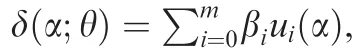
where The initial value for β is chosen to makeE(δ(α;θ))=0.Therefore,it is compulsory to haveE(θ)=0 in a linear model.Now,μC(α)and θ can be estimated from the data.Thus,the functional adjustment predictor is achieved as:1
This two-stage model building procedure prevents additional adjustments on the engineering model and helps to identify an engineering-statistical model with minimal adjustments.1
4.Numerical examples
In this section,to illustrate the application of the proposed models and the effectiveness of the proposed engineeringstatistical model for estimating the aerodynamic coefficients of a helicopter fuselage,three engineering-statistical models were developed to estimate the drag coefficientsCDof F2(Bell 212),F4(Bell 205)and F7(UH-60)fuselages at the desired angles of attack.Also,the accuracy of estimation of these models was compared with CFD method.Fig.5 shows the drag coefficients of F2,F4 and F7 fuselages obtained from wind tunnel test and the values obtained by CFD simulation.If wind tunnel test data are available for limited angles of attack,and there is a need to carry out predictions in points away from data,the predictions will be poor.
In order to build and validate the proposed model,wind tunnel test data were divided into two categories.The first category includes drag coefficient values of F2,F4 and F7 fuselages,respectively at angles of attack given as{-15°,-10°,-6°,0°},{-20°,-15°,-8°,-6°,-4°,-2°,0°,2°,4°,8°,10°,15°,20°,25°,40°}and{25°,30°,40°,50°,60°,70°},which were used in the construction of the model,and the second category includes drag coefficient values of F2,F4 and F7 fuselages respectively at angles of attack given as{-8°,-4°,-2°,4°,6°,15°},{-90°,-50°,-10°,6°,30°,90°}and{-80°,-25°,35°,45°,65°,80°},which were used in the validation process.19,24
In this section,based on Section 2 in which the engineering model building method for aerodynamic coefficients of helicopter fuselage was described,firstly,the engineering model to estimate the drag coefficient of F2,F4 and F7 fuselages were achieved(Eqs.(14)–(16))by fitting Fourier function(Eq.(1))on CFD data,of which the shape of function and the prediction bounds at 95%was provided in Fig.6.
Then,the sequential model building strategy presented in the previous section was used to create engineering-statistical models to estimate the drag coefficientCDof F2,F4 and F7 fuselages.Fig.7 shows the plot ofCD(the drag coefficient value from wind tunnel test)vsf(α)of F4 fuselage(the drag coefficient value obtained from the engineering model).From this plot,there exists evidence of a positive correlation of data obtained from wind tunnel test and engineering model.Also,the Pearson correlation coefficient was+1 which indicated a strong positive correlation between them.This subject is similar for F2 and F7 fuselages.Therefore,the proposed engineering model is useful for prediction.

F2:
The inadequacies of the model for constant adjustment models are calculated in Table 1,which are equal to 0.70327%,1.10185%and 2.63700%for F2,F4 and F7 fuselages respectively,and are far smaller than the inadequacy of the engineering model and the CFD method.The inadequacies of the engineering models obtained at this step,by applying constant adjustments,were greatly reduced and predictions derived from these models were of high accuracy.However,in order to show the full process of sequential model building,the second stage of the model improvement implied that the functional adjustment was applied.
To improve the accuracy of the constant adjustment model,the functional adjustment model is:
By plotting the residuals of the constant adjustment model of F4 fuselage vs the angles of attack(Fig.8)and after some trial and error,u1(α)= α,u2(α)= α2,u3(α)= α3andu

The inadequacies of the model for functional adjustment models of F2,F4 and F7 fuselages are 0.00741%,0.78936%,and 0.54670%(Table 1),which are smaller than the inadequacies of constant adjustment models,with values of 0.70327%,1.10185%and 2.63700%.For comparison of the models inadequacy,in addition to the criterion of the MPPE,other criteria such as the mean absolute error(MAE),mean bias error(MBE)and root mean square error(RMSE)can also be used.In Table 2,CFD method,engineering model,the constant adjustment and functional adjustment models of F4 fuselage have been compared according to the aforementioned criteria.From the table,functional adjustment model based on all criteria was better than the other models.However,according to Fig.8,it is evident that although the functional adjustment model in the observed points had a better fit to the data and had a higher accuracy than the constant adjustment model,the function form changed and demonstrated a different trend compared to the engineering model.In particular,the more the increase in the angle of attack the more the difference.According to the engineering model,an increase in the angle of attack of a fuselage resulted in a reduction in the slope of the drag coefficient curve of the fuselage,however this was not the case in the functional adjustment model.Therefore,in choosing the appropriate model for predicting the aerodynamic coefficient of a fuselage,in addition to the consideration of the criteria for measuring the model inadequacy,it is better to compare the prediction model function with the engineering model.As a general conclusion,it can be said that a prediction model having appropriate model adequacy measuring criteria and which follows the same trend as the engineering model,is more appropriate.
Also,the second set of wind tunnel test data can be used as a tool to select a more suitable model for estimating the aerodynamic coefficients of a fuselage and also to validate the pro-posed models.The interpolation and extrapolation of models can be determined using a validation process.
Table 1 Comparison of accuracy of CFD method with engineering model,constant adjustment model and functional adjustment model in drag coefficient estimation of F2,F4 and F7 fuselages.
The MPPE of F2,F4,and F7 fuselages for a number of angles of attack inside and outside the data range,such that modeling is complete on their basis,are provided in Tables 3 and 4,respectively.As evident in Table 4,for the data inside the range,the predictability for both constant adjustment models and functional adjustment models were appropriate,and the inadequacies of both models on the basis of the MPPE are close to each other.Consequently,constant adjustment and functional adjustment models offered a good interpolation capability.According to Table 4,for data outside the range,the functional adjustment models had a lot of errors and it can be concluded that these models exhibit poor extrapolation ability.In contrast,the inadequacies of the constant adjustment models were small and this issue indicated the appropriateness of the extrapolation ability for the constant adjustment model.Considering the aforementioned points,to estimate the drag coefficients of F2,F4,and F7 fuselages,constant adjustment model is proposed as the better model,because in addi-tion to having appropriate engineering precision and similar trend with the engineering model,it has good interpolation and extrapolation functionality.

Table 2 Comparison of accuracy of CFD method,engineering model,constant adjustment model and functional adjustment model in drag coefficient estimation of F4 fuselage.

Table 3 Comparison of CFD method,engineering model,constant adjustment and functional adjustment models on the basis of percentage positive error for data within the range of date modeling.

Table 4 Comparison of CFD method,engineering model,constant adjustment and functional adjustment models on the basis of percentage positive error for data outside the range of data modeling.
5.Conclusion
Models which describe the performance of a physical phenomenon are critical to design,predict,control and optimize.The analysis of fluid flow around a helicopter,in a macroscopic scale,so as to calculate the aerodynamic coefficients of helicopter fuselage,such as the dragCD,liftCLand pitching momentCm,is one of the key issues in the design of helicopters.To obtain fuselage aerodynamic coefficients,wind tunnel test and computational fluid dynamics simulation are used.Wind tunnel tests are very costly,time consuming and limited.Although the CFD method is less expensive,owing to the limitation of numerical solution,the number of nodes and the used solution,it is often not accurate and also has its own cost and time.In addition,carrying out a wind tunnel test at certain angles of attack is necessary for the validation of CFD results.
This paper aims to develop models which predicted the aerodynamic coefficients of helicopter fuselage at any desired angle of attack with appropriate engineering precision.This objective has been realized by combining and integrating computational fluid dynamics simulation and physical wind tunnel test.With such models,the design process can be accelerated,a tool is provided to aid designers with the prediction and optimization,and also there is significant reduction in the design costs.
Firstly,by modeling the helicopter fuselage in the intermediate and medium weights(the Bell 412,Bell 212,Bell 214,Bell 205,Agusta A109,Dauphin SA365N and UH-60),and using CFD simulation with Fluent software,aerodynamic coeff icients behavior of fuselage was analyzed.Then,using the CFD results and nonlinear regression,engineering models were developed which were able to predict the aerodynamic coefficients of the fuselage and demonstrate their trend.The JM method was modified and a validation step was included in orderto eliminateitsshortcomings.Theproposed engineering-statistical models were obtained by combining the engineering models,modified version of the JM method,and a few numbers of wind tunnel test data.These models were able to estimate the aerodynamic coefficients of the fuselage at any desired angle of attack with accuracy much higher than CFD and engineering models,in the shortest possible time.
Three numerical examples were provided to illustrate the model building strategy and demonstrate the effectiveness of the proposed engineering-statistical models.So,the engineering models were obtained to estimate the drag coefficients of the F2(Bell 212),F4(Bell 205),and F7(UH-60)fuselages by fitting Fourier model on CFD data.The engineeringstatistical models(constant adjustment and functional adjustment models)were developed based on the modified JM method.The accuracy of the proposed models of the F2,F4,and F7 fuselages were compared with the results of wind tunnel tests,CFD simulations and engineering models,based on MPPE.The inadequacies of the model for constant adjustment models of F2,F4 and F7 fuselages were equal to 0.70327%,1.10185%and 2.637%,and were far smaller than the inadequacies of CFD simulations(19.99476%,20.62754%,and 16.78131%) and engineering models (19.48765%,20.88905%,and 16.49641%)which show the appropriate engineering accuracy(a value usually less than 10%).The inadequacies of the model for functional adjustment models of F2,F4 and F7 fuselages were 0.00741%,0.78936%,and 0.54670%,which were smaller than the inadequacies of constant adjustment models.Also,the MAE,MBE,and RMSE criteria were used for comparison of the model inadequacies for engineering model,CFD simulation,constant adjustment and functional adjustment models of F4 fuselage.The results of the evaluation were similar according to all criteria.The results show the accuracy and efficiency of the introduced engineering-statistical model.
It was also observed that,in addition to considering the criteriaofthemodelinadequacy,thefunctionformandtrendwere also important and should have a similar trend to the engineering model.Regarding the drag coefficient plots,it was observed that although the functional adjustment model on the basis of criteria of the model inadequacy was preferable to the constant adjustment model,due to its different trend when compared with the engineering model,the constant adjustment model was chosen as better engineering-statistical model to predict the drag coefficient of the fuselages.This was proved by the evaluation of the interpolation and extrapolation ability of the proposed models.The interpolation capability of both constant adjustment models and functional adjustment models of F2,F4,and F7 fuselages were appropriate and the inadequacies ofbothmodelsonthebasisoftheMPPEwerelessby1.5%.The functional adjustment models exhibited poor extrapolation capabilities and had a lot of errors.The inadequacies of the functional adjustment models of the F2,F4 and F7 fuselages were 84.80448%,38.53608%,and 125.27220%.In contrast,the extrapolation capability of the constant adjustment models wasappropriateandcontainedlittleerrorsascomparedtowind tunnel test data(8.51937%,1.181403%,and 2.87331%,respectively).Consequently,the superiority of the constant adjustment model was demonstrated.
In future researches,the development of the engineering model and engineering-statistical model for aerodynamic coefficients of the fuselage on the basis of a helicopter yaw angle is suggested.Also,the development of such models for attack helicopters will be very valuable and important.On the other hand,the described model building strategy can also be used to model other physical phenomena.
1.Joseph V Roshan,Melkote SN.Statistical adjustments to engineering models.J Qual Technol2009;41(4):362–75.
2.Chang CJ,Roshan Joseph V.Model calibration through minimal adjustments.Technometrics2014;56(4):474–82.
3.Kang L,Roshan Joseph V.Kernel approximation:from regression to interpolation.JUncertaintyQuantification2016;4(1):112–29.
4.Qian Z,Seepersad CC,Roshan Joseph V,Allen JK,Wu CFJ.Building surrogate models based on detailed and approximate simulations.J Mech Des2006;128(4):668–77.
5.Plumlee M,Roshan Joseph V,Wu CFJ.Comment:alternative strategies for experimental design.Technometrics2013;55(3):289–92.
6.Ba S,Jain N,Roshan Joseph V,Singh RK.Integrating analytical models with finite element models:an application in micromachining.J Qual Technol2013;45(2):200–12.
7.Roshan Joseph VR,Kang L.Regression-based inverse distance weighting with applications to computer experiments.Technometrics2011;53(3):254–65.
8.Bayarri MJ,Berger JO,Paulo R,Sacks J,Cafeo J,Cavendish J,et al.A framework for validation of computer models.Technometrics2007;49(2):138–54.
9.Plumlee M.Fast prediction of deterministic functions using sparse grid experimental designs.JAmStatAssoc2014;109(508):1581–91.
10.Biava M,Vigevano L.Simulation of a complete helicopter:A CFD approach to the study of interference effects.Aerosp Sci Technol2012;19(1):37–49.
11.Steijl R,Barakos GN.CFD analysis of complete helicopter configurations—lessons learnt from the GOAHEAD project.Aerosp Sci Technol2012;19(1):58–71.
12.Antoniadis AF,Drikakis D,Zhong B,Barakos G,Steijl R,Biava M,et al.Assessment of CFD methods against experimental flow measurements for helicopter flows.Aerosp Sci Technol2012;19(1):86–100.
13.Higdon D,Kennedy M,Cavendish JC,Cafeo JA,Ryne RD.Combining field data and computer simulations for calibration and prediction.J Sci Comput2004;26(2):448–66.
14.Xiong Y,Chen W,Tsui KL,Apley DW.A better understanding of model updating strategies in validating engineering models.Comput Method Appl M2009;198(15–16):1327–37.
15.Hung Y,Joseph V Roshan,Melkote SN.Analysis of computer experiments with functional response.Technometrics2015;57(1):35–44.
16.Dasgupta T,Weintraub B,Joseph V Roshan.A physical-statistical model for density control of nanowires.IIE Trans-Quality Reliability Eng2011;43(4):233–41.
17.White FM.Fluid mechanics.7th ed.New York:McGraw-Hill;2011.p.150–249.
18.Wang Q,Zhao Q,Wu Q.Aerodynamic shape optimization for alleviating dynamic stall characteristics of helicopter rotor airfoil.Chin J Aeronaut2015;28(2):346–56.
19.Hilbert KB.A mathematical model of the UH-60 helicopter.Washington,D.C.:NASA;1984.Report No.:NASA/TM-85890 and USAAVSCOM TM-84-A-2.
20.Brand AG,McMahon HM,Komerath NM.Surface pressure measurements on a body subject to vortex wake interaction.AIAA J1989;27(5):569–74.
21.Kim JM,Komerath NM.Summary of the interaction of a rotor wake with a circular cylinder.AIAA J1995;33(3):470–8.
22.Biava M,Khier W,Vigevano L.CFD prediction of air flow past a full helicopter configuration.Aerosp Sci Technol2012;19(1):3–18.
23.Bates DM,Watts DG.Nonlinear regression analysis and its applications.2nd ed.New York:Wiley;2007.p.33–67.
24.Prouty RW.Helicopter performance,stability,and control.2nd ed.Florida:Krieger Publishing Company;2001.p.515–698.
2 February 2016;revised 6 May 2016;accepted 4 July 2016
Available online 22 December 2016
Ⓒ2016 Chinese Society of Aeronautics and Astronautics.Production and hosting by Elsevier Ltd.This is anopenaccessarticleundertheCCBY-NC-NDlicense(http://creativecommons.org/licenses/by-nc-nd/4.0/).
*Corresponding author.
E-mail addresses: hossein.sheikhi@srbiau.ac.ir (H. Sheikhi),a.saghaei@srbiau.ac.ir(A.Saghaie).
Peer review under responsibility of Editorial Committee of CJA.
 CHINESE JOURNAL OF AERONAUTICS2017年1期
- CHINESE JOURNAL OF AERONAUTICS的其它文章
- Anti-plane problem of four edge cracks emanating from a square hole in piezoelectric solids
- Stress analysis and damage evolution in individual plies of notched composite laminates subjected to in-plane loads
- Drilling load modeling and validation based on the filling rate of auger flute in planetary sampling
- An adaptive attitude algorithm based on a current statistical model for maneuvering acceleration
- Spacecraft attitude maneuver control using two parallel mounted 3-DOF spherical actuators
- Angular velocity determination of spinning solar sails using only a sun sensor