
Optimization and design of an aircraft’s morphing wing-tip demonstrator for drag reduction at low speeds,Part II-Experimental validation using Infra-Red transition measurement from Wind Tunnel tests
2017-11-21 12:53:38AndreeKorenschiOliviuSugrGorJornAcottoGuillumeBrinchonGregoirePortierRuxndrMihelBotezMhmoudMmouYoussefMerki
CHINESE JOURNAL OF AERONAUTICS 2017年1期
Andree Korenschi,Oliviu Sugr Gor,Jorn Acotto,Guillume Brinchon,Gregoire Portier,Ruxndr Mihel Botez,*,Mhmoud Mmou,Youssef Merki
aLARCASE Laboratory of Applied Research in Active Control,Avionics and Aeroservoelasticity,E´cole de Technologie Supe´rieure,Montreal H3C1K3,Canada
bAerodynamics Laboratory,NRC Aerospace,National Research Council Canada,Ottawa K1A0R6,Canada
Optimization and design of an aircraft’s morphing wing-tip demonstrator for drag reduction at low speeds,Part II-Experimental validation using Infra-Red transition measurement from Wind Tunnel tests
Andreea Koreanschia,Oliviu Sugar Gabora,Joran Acottoa,Guillaume Brianchona,Gregoire Portiera,Ruxandra Mihaela Boteza,*,Mahmoud Mamoub,Youssef Mebarkib
aLARCASE Laboratory of Applied Research in Active Control,Avionics and Aeroservoelasticity,E´cole de Technologie Supe´rieure,Montreal H3C1K3,Canada
bAerodynamics Laboratory,NRC Aerospace,National Research Council Canada,Ottawa K1A0R6,Canada
Drag reduction;Infra-red tests;Morphing wing;Optimization;Wind tunnel tests
In the present paper,an ‘in-house’genetic algorithm was numerically and experimentally validated.The genetic algorithm was applied to an optimization problem for improving the aerodynamic performances of an aircraft wing tip through upper surface morphing.The optimization was performed for 16 flight cases expressed in terms of various combinations of speeds,angles of attack and aileron deflections.The displacements resulted from the optimization were used during the wind tunnel tests of the wing tip demonstrator for the actuators control to change the upper surface shape of the wing.The results of the optimization of the flow behavior for the airfoil morphing upper-surface problem were validated with wind tunnel experimental transition results obtained with infra-red Thermography on the wing-tip demonstrator.The validation proved that the 2D numerical optimization using the ‘in-house’genetic algorithm was an appropriate tool in improving various aspects of a wing’s aerodynamic performances.
1.Introduction
Nowadays,applications of optimization algorithms can be found in almost all industrial and academic research venues,such as optimization electric circuitry,1stock market predictions,2image quality problems,3software implementation problems,4to optimization of aircraft structures,aerodynamics or flight trajectories,etc.
In the aerospace field,many research projects and collaborations include the successful implementation of the more traditional metaheuristic optimization algorithms such as genetic algorithm,5beecolony algorithm,6artificialneuralnetworks,7,8or ant colonies optimization in their research for new optimized flight trajectories,for new optimized wing shapes or improved control.
One such collaboration took place between the teams from the Laboratory of Applied Research in Active Control,Avionics and Aeroservoelasticity(LARCASE)laboratory and CMC electronics-esterline on the Green Aviation Research Development Network(GARDN)project,which was funded by the Green Aviation Research Development Business Led Network in its second round.9,10The main objective of the collaboration was to optimize the vertical and horizontal paths of the aircraft within the flight management system by taking into account the required time of arrival,the wind grids and meteorological conditions.The main motivation of the project was to reduce overall carbon emissions and flight costs.
Morphing also consists in changing the structure or appearance of an aircraft during flight by modifying the wing sweep,11span,12chord13or camber,14,15by the high lift devices16,17orthe fuselage,forsmallaircraftand for unmanned aerial vehicle(UAV).18,19
Applications of optimization techniques for UAVs were described by Gamboa et al.20who designed an UAV wing capable of independent span and chord changes,using a telescopic spar and a rib system.The numerical analysis demonstrated a drag reduction of up to 23%when compared to its nonmorphing base geometry.Falca˜o et al.21designed and tested a morphing winglet for a military UAV and achieved important performance improvements by changing the winglet cant and toe angles.Other research on UAV wing morphing was done by Sugar et al.,22,23where the upper-surface of the wing was optimized on a segment between its leading edge and 55%of the chord,and also explored morphing of the full wing’s geometry.Hu and Yu24developed a multi-disciplinary optimization for improving aerodynamic,stealth and structural performances of an unmanned aerial combat vehicle.Li et al.25developed a methodology for aerodynamic optimization aimed at demonstrating the performances of a blended wing body transport,while Xie et al.26studied the effects of static aeroelastic phenomena on very flexible wings.
Few projects concentrate on the effect of the morphing technologies on the aerodynamic performances of the wing;the majority concentrate mostly on aerodynamic and structural interactions for the purpose of demonstrating the increased safety against undesired aeroelastic phenomena such as flutter.27–29
A recent experiment,where the aerodynamic performances of active morphing wings were studied,was the CRIAQ 7.1 project,in which collaboration took place between aerospace industrial teams from Bombardier Aerospace and Thales Canada,and academic partners from the E´cole de Te´chnologie Supe´rieure(ETS)and E´cole Polyte´chnique of Montreal,and the Canadian National Research Council(CNRC)team.The purpose of the project was to demonstrate the capabilities of morphing wings in a wind tunnel for developing the flow transition from laminar to turbulent.30,31Morphing was achieved by replacing the upper surface of the wing,spanned between 7%and 70%of the wing chord,by a flexible carbon-Kevlar composite skin.The skin morphing was achieved using two shape memory alloy(SMA)actuation lines with the aim to obtain an optimized shape for each flight condition tested in the wind tunnel.32The optimization was done using a genetic algorithm method coupled with the aerodynamic solver XFoil.The wind tunnel tests had proven that the concept of upper surface morphing was viable,controllable,and provided tangible results by confirming the delay of the transition from laminar to turbulent flow,which induced a substantial reduction in the drag coefficient.33Proportional integrated derivative(PID)34and neuro-fuzzy controllers35were tested to prove the controllability of the flexible skin shape and the morphing mechanisms towards the transition delay.It appeared that the controllers demonstrated an excellent performance in both open36and closed loops.37
The research presented in this present paper was done within the framework of the international CRIAQ MDO505 Morphing Wing Project,which was a continuation of the previous research project CRIAQ 7.1,and aimed at a higher technical readiness level by considering a real wing internal structure and a certifiable electric control system and controllers.The participants in this project were ETS,Ecole Polytehnique and University of Naples ‘Federico II’as academia research partners,the CNRC and the Italian Aerospace Research Center(CIRA)as research center partners and Bombardier Aeronautique,Thales Canada and Alenia Aermacchi as industrial partners.
The objectives of the project were to design,manufacture and control a wing demonstrator based on an aircraft wingtip equipped with both a conventional and adaptive aileron.The novelty of the CRIAQ MDO 505 project consisted in its multidisciplinary approach,where structure,aerodynamics,control and experimental design were combined to design and manufacture an active morphing wing demonstrator and test it under subsonic wind tunnel conditions.
Part I of this paper established the design and optimization of a wing-tip demonstrator airfoil using an ‘in-house’genetic algorithm coupled with the XFoil aerodynamic 2D solver that used the eNmethod for the numerical determination of the transition point.38,39The algorithm was described in detail,and its results were compared with the results obtained by other optimization methods,namely the bee colony method and the gradient method.Also,another experimental validation of the genetic algorithm was performed for the ATR 42 wing airfoil in Koreanschi et al.40Validation of the optimization technique and numerical results were achieved through experimental data obtained through wind tunnel tests of a wing model demonstrator.The optimization concentrated on the improvement of the upper-surface behavior of the flow by manipulating the position of transition from fully laminar to fully turbulent flow.The optimization was carried at the airfoil level and in practice,was applied to a full scale wing tip with aircraft-look-alike internal structure.The validation was done through comparison of the numerical and experimental results for a specific region on the wing,where Kulite sensors were installed for pressure measurements.
2.Wing tip demonstrator with conventional aileron
The full-scale morphing wing model was an optimized structure with a 1.5 m span and 1.5 m root chord,a taper ratio of 0.72 and leading and trailing edges sweep angle of 8°.The wing box and its internal structure(spars,ribs,and lower skin)were manufactured from aluminum alloy material,while the adaptive upper surface was positioned between 20%and 65%of the wing chord.The adaptive upper surface skin was specif ically designed and optimized to meet industrial partner’s requirements.The adaptive skin was manufactured using carbon fiber composite materials.41
The deformation of the skin shape,driven by actuators placed inside the wing box structure,was a function of the flight condition(de fined in terms of Mach number,Reynolds number and angle of attack).These actuators were speci fically designed and manufactured to meet in- flight and wind tunnel test requirements.Four electrical actuators were installed on two actuation lines;two actuators were installed on each line,were placed at 37%and 75%of the wing span,and were fixed to the ribs and to the composite skin.Each actuator has the ability to operate independently from the others.On each actuation line,the actuators were positioned at 32%and 48%of the local wing chord.
The aileron’s hinge was located at 72%of the chord.Two ailerons type were designed and manufactured.One aileron was structurally rigid,while the other one represented a new morphing aileron concept.Both ailerons were designed to be attached to the same hinge axis of the wing box,and both were able to undergo a controlled deflection between-7°and+7°.Fig.1 presents a sketch of the morphing wing model concept as it was mounted and tested at the NRC subsonic wind tunnel.
3.Wind tunnel description and infra-red data acquisition
The wind tunnel tests were performed at the 2 m×3 m atmospheric closed circuit subsonic wind tunnel of the CNRC.This atmospheric wind tunnel can operate at a maximum Mach number of 0.33.
The upper surface flexible skin was equipped with 32 high precision Kulite piezoelectric-type transducers42for pressure measurement on the flexible skin that were further processed to determine the laminar-to-turbulent transition location.These sensors were installed in two staggered lines(with 16 Kulite sensors on each line),situated respectively at 0.600 m and 0.625 m from the wing root section.In addition to the Kulite piezoelectric sensors,at the same two spanwise stations,60 static pressure taps were installed(30 taps on each line)on the wing leading edge,lower surface and aileron,thus providing complete experimental pressure distribution around the wing cross section at 40%of the wing span.The pressure sensors were installed in a staggered fashion to minimize the interference between sensors.
The experimental measurements also included the use of a wake rake pressure acquisition system for the purpose of measuring the wing profile drag at different span-wise positions,and also the use of a wind tunnel balance for measuring the aerodynamic forces and moments.Fig.2 presents the MDO 505 morphing wing model installed in the tunnel test section,viewed from both the leading edge(LE)(Fig.2(a))and the trailing edge(TE)(Fig.2(b)).
Infra-red(IR)thermography camera visualizations were performed for capturing the transition region over the entire wing model surface.The wing leading edge,its upper surface flexible skin and the aileron interface were coated with high emissivity black paint to improve the quality of the IR photographs.The span-wise stations,where the two pressure sensors lines were installed,were not painted,in order to not influence the pressure reading quality.A Jenoptik Variocam camera,43with a resolution of 640 by 480 pixels,was used to measure the surface temperatures.This camera was equipped with 60°lens in order to capture the flow transition on the entire upper surface of the wing.
The IR thermography visualization allowed the identification of the transition region between laminar and turbulent regimes,based on the analysis of the model surface temperature.Examples of infra-red photography results are given in Section 5.The turbulent flow regime increases the convective heat transfer between the model and the flow with respect to the laminar boundary layer.As a result,a flow temperature change,introduced by the wind tunnel heat exchanger system,will cause different temperature changes over the model,depending on the behavior of the boundary layer.
4.Optimization algorithm
The genetic algorithm was applied to the problem of airfoil upper-surface morphing.The problem objective was the search of the optimum shapes for an airfoil through local thickness modifications with the aim to improve the upper surface flow and thus the aerodynamic performances of the wing’s airfoil.
Thelocalwingthicknessmodification wasobtained through four actuations points,as described in the previous section.The shape of the flexible upper-surface was obtained by an optimized combination of the four vertical displacements,representing the local ‘pushing and pulling’actions of four electric actuators installed inside the wing box.The vertical displacements resulted from the genetic optimization of the wing’s airfoil.
For the theoretical thin airfoil provided by Bombardier,considered under the name CRIAQ MDO 505 wing demonstrator airfoil,the optimization and design approach was more conservative in nature,as many structural requirements and constraints were taken into account when performing the optimization.
Table 1 presents the morphing surface limits,number and position of actuators on each rib as well as the maximum displacements,%cmeans the percentage of the chord.
Theproblem ofairfoilupper-surfacemorphing for improvement of the aerodynamic behavior of wings is not a problem with a single solution.More often than not,as it was presented in Section 1 of this paper,there is an optimum region where several possible solutions coexist and any of them can be considered as the final solution to the problem.
A full description of the methodology used for the optimization algorithm and its numerical results was provided in Section 1 of this paper.Fig.3 presents the workflow diagram of the algorithm that was used for the optimization.
Table 2 presents the parameters used for the optimization of the 16 cases tested during the wind tunnel tests of the wing demonstrator.
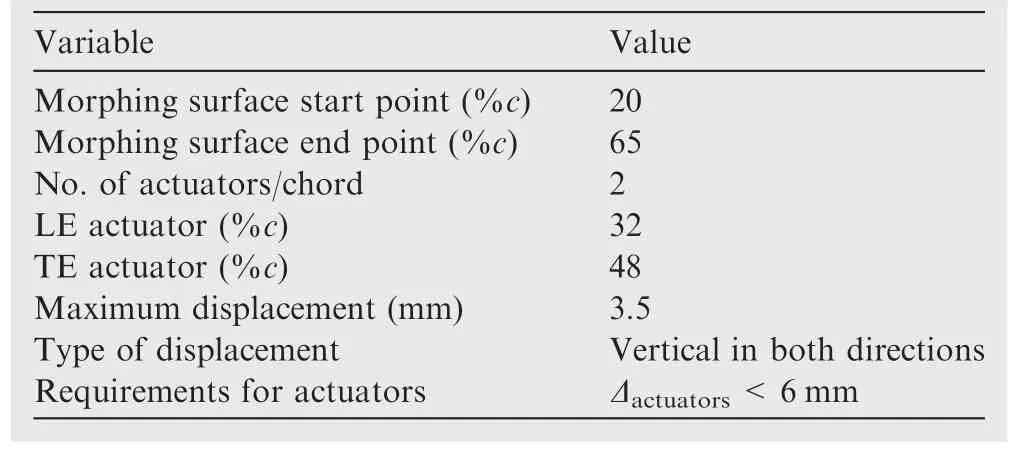
Table 1 Morphing problem variable values for MDO 505 wing demonstrator airfoil.
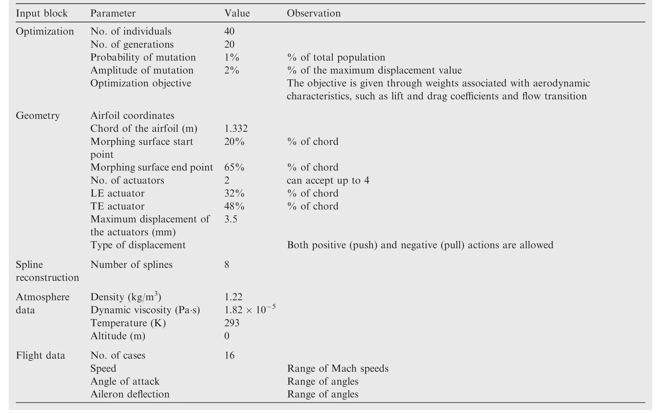
Table 2 Input blocks and parameters for MDO 505 demonstrator airfoil.
5.Optimization simulation vs experimental results
In this section,the optimization of the MDO 505 wing airfoil is presented.The optimization was performed using the parameters provided in Section 4,Table 2.The optimization results,provided as actuator displacements in mm,were used by the control team to perform the upper-surface morphing of the wing-tip demonstrator during the wind tunnel tests.
The results were presented as numerical transition points for the wing section,and as experimental transition regions extracted from Infrared Thermography for the same wing section where the pressure sensors were installed(Figs.4 and 5).
The two sets of results,numerical and experimental,were firstly compared to assess the agreement between numerical and experimental values,and secondly to assess the optimization success during experimental tests and compare it to the numerical optimization expectation.
The optimization was run for two main objectives:transition delay towards the trailing edge(Eq.(1)),which means possible drag coefficient reduction,and transition advancement towards the leading edge(Eq.(2)),which could stabilize the boundary layer at high speeds or high angles of attack and aileron deflections.
whereFfrepresents the fitness function and UpTrrepresents the airfoil’s upper surface transition position.
Table 3 presents the 16 cases studied and the numerical results obtained with the genetic algorithm optimization for both objective functions.
The experimental tests were done at the CNRC subsonic wind tunnel located in Ottawa/Ontario.The wind tunnel and the MDO 505 wing demonstrator used during the experiments were described in the above Section 2 of the present paper.
The experimental transition location results were obtained with IR thermography;the results for the section of interest on the wing were extracted using MATLAB software;the IR system was described in Section 3.The IR data postprocessing steps consisted of:correction of the lens distortions,of the perspective view and projection onto the physical geometry.The detection of the transition region was fully automated by looking at the local temperature gradients on the wing surface.The final outputs of the data analysis were:the transition region(delimited by white dotted lines on the images),the mean transition front spanning the whole wing span,and the mean transition at the Kulite pressure sensors station to compare with the CFD simulations.Figs.4 and 5 present examples of IR results for three of the cases from Table 3.
The black dashed lines in Figs.4 and 5 correspond to the section of the wing demonstrator where the Kulite pressure sensors were installed,and also,represent the section chord for which the optimization was performed.The optimization was done for the section where the first line of actuators was installed,then it was linearly extrapolated for the second line of actuators,which is close to the tip of the wing demonstrator.
The experimental transition was presented as a ‘region’and the numerical transition point obtained with XFoil’s eNmethod was matched to this region.If the numerical transition point was inside the experimental transition region,then it was considered that the numerical and experimental results were in good agreement.If the numerical transition was outside the experimental transition region,then an error was calculated between the numerical value and the closest boundary value.If the calculated error was less than 6%,the error was considered as acceptable.44
Fig.6 presents an example where the numerical transition matched the experimental transition region and an example where the numerical transition did not match.
As shown in Fig.6,the numerical transition point was found to be situated inside the experimental transition region boundaries for Case 5,and in this case,a good agreement between numerical and experimental data existed,while in Case 6,the numerical transition was situated with 6%of the chord outside the lowest boundary of the experimental transition region,and it was viewed as having an acceptable error between numerical and experimental transition.
5.1.Comparison between numerical and experimental transition data
Figs.7 and 8 show the comparison that was made between the numerically determined transition point and the experimental transition region from Infrared readings for the un-morphed,and for the morphed wing demonstrator.This comparison was done to show the agreement between the numerical and the experimental transition data.

Table 3 Optimization cases and results for wing tip demonstrator.
It was possible to successfully compare the numerical results obtained for the wing’s airfoil to the experimental transition results extracted for a specific section corresponding to Kulite sensors localization from the global experimental results of the entire wing demonstrator.
In Figs.7 and 8,the presented results show that with the exception of 3 un-morphed wing cases(Cases 6,7 and 9),the numerical transition was situated inside the experimental transition boundaries.
Tables 4 and 5 present the errors found for the 16 cases described in Table 3;Table 4 presents the errors for the unmorphed wing demonstrator transition results and Table 5 for the morphed wing demonstrator transition results.
The error was calculated as the difference between the numeric transition value and the closest experimental transition region boundary:
When the error is 0 the numerical transition was situated inside the experimental transition region.
5.2.Evaluation of experimental transition optimization
This section presents the behavior of the upper-surface morphing during experimental testing on the MDO 505 wing demonstrator.In Fig.9,the experimental un-morphed and morphed wing section transition regions were overlapped for a better view of the effects of the upper-surface morphing on the length and position of the transition region in the studied section.
The experimental transition region is characterized by an upper and a lower boundary.The lower boundary of the transition region represents the point where the flow starts its transition from fully laminar flow towards turbulent,while the upper boundary of the transition region represents the location at which the flow can be considered as being fully turbulent.Therefore,the optimization of the transition region refers to modifications in the desired direction of the upper and lower boundaries,depending on the optimization objective to be accomplished.
As such,two parameters were calculated:τ,which represents the difference between the morphed and un-morphed transition region(TR)upper boundary values and describes how much the onset of the fully turbulent flow was modified,
where UB means upper-boundary,and λ,which represents the difference between the morphed and un-morphed TR lower boundary values and describes with how much the boundary of the fully laminar flow was modified.
where LB means lower-boundary.
Fig.9(a)shows the comparison between the un-morphed and morphed wing transition regions for the objective of flow transition delay from fully laminar to fully turbulent.It could be observed from the above figure that the onset of the fully turbulent flow was delayed for 7 cases out of 8,with the maximum delay being achieved for Case 7 with 7.65%c.The end of the laminar flow was also delayed in 6 cases,with the maximum delay being again for Case 7 with 5.65%c.For Case 1,the transition region of the morphed wing was extended in comparison with the original wing,while for Case 4 the difference between the two regions was almost negligible.Case 5 was the one case where the transition optimization was not successful,but the difference between the two transition regions was also very small.
Table 6 presents the values for the two parameters described in the first part of the section,τ and λ,for the cases where the optimization was aimed at delaying the transition from laminar towards turbulence of the upper-surface flow.
Fig.9(b)shows the comparison between the un-morphed and morphed wing transition regions for the objective of advancing transition towards the leading edge.
From Fig.9(b),it appeared that the onset of the fully turbulent flow was advanced towards the leading edge for all cases,with the maximum advancement being achieved for Case 15 with 18.64%c.The end of the laminar flow was also advanced towards the leading edge in all cases,with the maximum advancement being again for case 15 of 20.64%c.For Cases 10 and 13 the length of the transition region was reduced through the morphing of the upper surface,while for Cases 14–16 the length of the transition region was a little bit extended;all the other cases had an unchanged length of the transition region.
Table 7 presents the values for the two parameters described in the first part of the section,τ and λ,for the cases where the optimization was aimed at advancing the transition on the wing upper-surface.
Fig.10 displays a comparison between the numerical transition optimization prediction and the resulted experimental optimization.Fig.10(a)shows the comparison between the numerical optimization prediction based on XFoil results and the τ and λ results with the objective to delay transition,while Fig.10(b)presents the comparison between the numerical prediction and the τ and λ results with the objective of advancing transition.The two figures assess the differencesbetween the numerical optimization predictions and the experimental results.
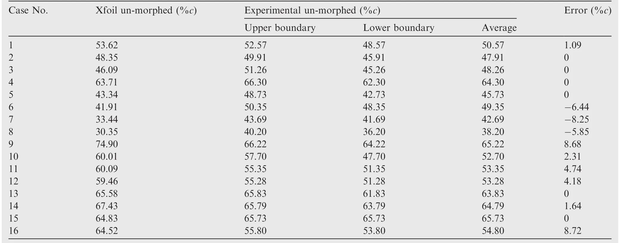
Table 4 Transition intervals and values for numerical and experimental cases and error between the results(un-morphed wing).
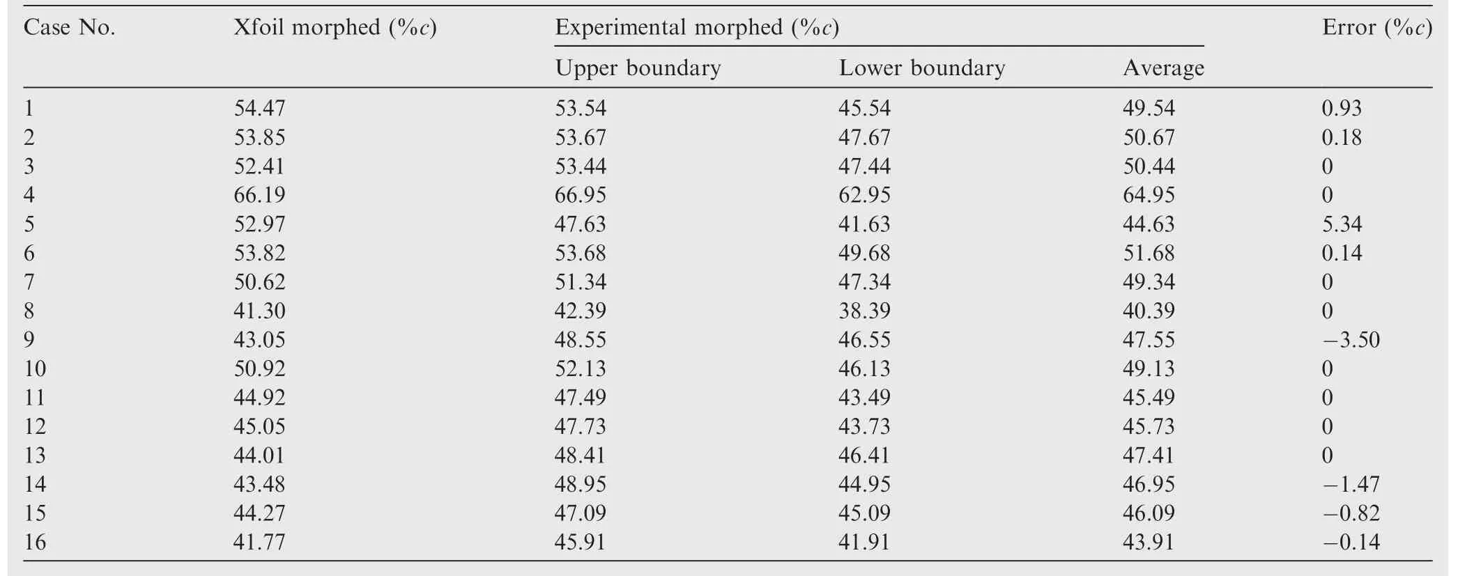
Table 5 Transition intervals and values for numerical and experimental cases and error between the results(morphed wing).
From Fig.10,it could be observed that for most of the cases the numerical optimization had overestimated the transition delay or advancement,with some cases where the difference is almost double.For Cases 1–4,10 and 15 the numerical prediction was close to the transition obtained experimentally during the wind tunnel tests.
The overestimation of the transition optimization cannot be imputed to a single aspect or point in a single direction where an error could be found;as the designed and manufactured MDO 505 wing demonstrator was the result of a multidisciplinary project, where many aerospace disciplines interacted,any variation of any of the multiple variables pertaining to structure,aerodynamics,control,integration or experiment could have affected the outcome of the results.Nonetheless,despite the existing differences between the numerical predictions and the experimental results,the optimization of the MDO 505 wing through morphing of the upper surface by using actuator displacements resulted from a numerical optimization with an ‘in-house’Genetic Algorithm coupled with a bi-dimensional aerodynamic solver using the eNmethod was considered as successful.
6.Conclusions
In this paper,an ‘in-house’genetic algorithm was applied to the problem of optimizing the shape of the upper surface of an airfoil by using actuator displacements.In the first part of the paper it was shown that the genetic algorithm used for the optimization of the wing tip demonstrator airfoil gave very good results in comparison with two other optimization methods and it always reached the global optimum region.It was shown that the algorithm was robust and that it converged towards the optimum area in less than 10 iterations or generations,while other 10 generations were used to ensure the stability of the solution and that this solution was found in the global optimum area.
Finally,the genetic algorithm was used to optimize the airfoil shape for 16 cases,with the aim to satisfy two objectives:delay of the transition towards the trailing edge of the airfoil,and advancement of the flow transition towards the leading edge.The displacements resulted from the optimization were used for the upper surface morphing controller during wind tunnel testing on the MDO 505 wing demonstrator andcomparisons were conducted between the experimental transition regions of the morphed and un-morphed wing–section by using Infrared Thermography.For the success of this optimization,two new parameters were introduced, τ and λ,to describe the behavior of the flow when it passed from fully laminar to fully turbulent.Both objectives were successfully attained for most of the cases using the displacements provided by the numerical optimization.Maximum delays of the transition region were up to 7.6%of the chord and for the forward displacement of the transition region were of up to 20%of the chord.

Table 6 Parameters λ and τ describing effects of morphing wing on flow behavior for transition delay objective.

Table 7 Parameters λ and τ describing effects of morphing wing on flow behavior,for transition advance towards leading edge objective.
The experimental optimization results were then compared with the numerical simulation results,it was found that the numerical optimization was overestimated due to a multitude of factors starting with the numerical solver,and ending with the multidisciplinary aspect of the project that introduced a high number of variables that could affect the numerical optimization.Nonetheless,the numerical optimization was an important tool for preliminary estimation and evaluation of the morphing possibilities and the GA presented in this paper and could be successfully used for performing optimization of the wing’s upper-surface morphing problem.Also it would be interesting to compare its results to those that could be obtained with more recent optimization methods such as those based on mathematical behavior.
Acknowledgments
We would like to thank to Bombardier Aerospace,Thales Canada,The Consortium in Research and Aerospace in Canada(CRIAQ),and to the Natural Sciences and Engineering Research Council of Canada(NSERC)for their financial support.Special thanks are dues to our collaborators and leaders in this project:Mr.Patrick Germain and Mr.Fassi Kafyeke from Bombardier Aerospace,Mr.Eric Laurendeau from Ecole Polytechnique,Mr.Philippe Molaret from Thales Canada,and Mr.Erik Sherwood and his team from DFSNRC for the wing model design and fabrication.
1.Zhang H,Ye D.An artificial bee colony algorithm approach for routing in VLSI.Advances in swarm intelligence.Berlin Heidelberg:Springer;2012.p.334–41.
2.Majhi R,Panda G,Majhi B,Sahoo G.Efficient prediction of stock market indices using adaptive bacterial foraging optimization(ABFO)and BFO based techniques.Expert Syst Appl2009;36(6):10097–104.
3.Cui SY,Wang ZH,Tsai PW,Chang CC,Yue S.Single bitmap block truncation coding of color images using cat swarm optimization.Recent advances in information hiding and applications.Berlin Heidelberg:Springer;2013.p.119–38.
4.Bacanin N.Implementation and performance of an objectoriented software system for cuckoo search algorithm.Int J Math Comput Simul2012;6(1):185–93.
5.Sugar OG,Koreanschi A,Botez RM.Low-speed aerodynamic characteristics improvement of ATR 42 airfoil using a morphing wing approach.IIECON 2012-38th annual conference on IEEE industrial electronics society.Piscataway(NJ):IEEE Press;2012.p.5451–6.
6.Gabor SO,Simon A,Koreanschi A,Botez RM.Aerodynamic performance improvement of the UAS-S4 E´hecatl morphing airfoil using novel optimization techniques.Proc Inst Mech Eng,Part G:J Aerosp Eng2016;230:1164–80.
7.Mosbah AB,Salinas MF,Botez RM,Dao TM.New methodology for wind tunnel calibration using neural networks-EGD approach.SAE Int J Aerosp2013;6(2):761–6.
8.Mosbah AB,Botez RM,Dao TM.New methodology for calculating flight parameters with neural network–EGD methodAIAA modeling and simulation technologies(MST)conference.Reston:AIAA;2013.p.19–22.
9.Patron RF,Botez RM,Labour D.New altitude optimisation algorithm for the flight management system CMA-9000 improvement on the A310 and L-1011 aircraft.Roy Aeronaut Soc2013;117:787–805.
10.Patro´n F,Salvador R,Kessaci A,Botez RM.Horizontal flight trajectories optimisation for commercial aircraft through a flight management system.Aeronaut J2014;118(1210):1499–518.
11.Joo JJ,Sanders B,Johnson T,Frecker MI.Optimal actuator location within a morphing wing scissor mechanism configuration.Proceeding of SPIE2006.
12.Neal DA,Good MG,Johnston CO,Robertshaw HH,Mason DJ,Inman DJ.Design and wind-tunnel analysis of a fully adaptive aircraft configurationProceedings of AIAA/ASME/ASCE/AHS/ASC SDM.Reston:AIAA;2004.
13.Reed Jr JL,Hemmelgarn CD,Pelley BM,Havens E.Adaptive wing structures.Proceeding of SPIE2005;132–42.
14.Poonsong P.Design and analysis of a multi-section variable camber wing[dissertation].Maryland:University of Maryland;2004.
15.Monner HP,Hanselka H,Breitbach EJ.Development and design of flexible fowler flaps for an adaptive wing.5th annual international symposium on smart structures and materials.1998.p.60–70.
16.Pecora R,Barbarino S,Lecce L,Russo S.Design and functional test of a morphing high-lift device for a regional aircraft.J Intell Mater Syst Struct2011;22(10):1005–23.
17.Pecora R,Magnifico M,Amoroso F,Monaco E.Trade-off flutter analysis of a morphing wing trailing edge.6th ECCOMAS conference on smart structures and materials.2013.
18.Sugar OG,Koreanschi A,Botez RM.Optimization of an unmanned aerial system’wing using a flexible skin morphing wing.Report No.:2013-01-2095.Pennsylvania:SAE International;2013.
19.Sugar OG,Simon A,Koreanschi A,Botez RM.Improving the UAS-S4 E´hecal airfoil high angles-of-attack performance characteristics using a morphing wing approach.Proc Inst Mech Eng,Part G:J Aerosp Eng2016;230(7):1164–80.
20.Gamboa P,Vale J,Lau PFJ,Suleman A.Optimization of a morphing wing based on coupled aerodynamic and structural constraints.AIAA J2009;47(9):2087–104.
21.Falca˜o L,Gomes AA,Suleman A.Aero-structural design optimization of a morphing wingtip.J Intell Mater Syst Struct2011;22(10):1113–24.
22.Sugar OG,Koreanschi A,Botez RM.Numerical optimization of the S4 E´hecatl UAS airfoil using a morphing wing approachAIAA 32nd applied aerodynamics conference.Reston:AIAA;2014.
23.Sugar OG,Simon A,Koreanschi A,Botez RM.Application of a morphing wing technology on hydra technologies unmanned aerial system UAS-S4ASME 2014 international mechanical engineering congress and exposition.New York:ASME;2014.
24.Hu TY,Yu XQ.Aerodynamic/stealthy/structural multidisciplinary design optimization of unmanned combat air vehicle.Chin J Aeronaut2009;22(4):380–6.
25.Li PF,Zhang B,Chen YC,Yuan CS,Lin Y.Aerodynamic design methodology for blended wing body transport.Chin J Aeronaut2012;25(4):508–16.
26.Xie CC,Wang L,Yang C,Liu Y.Static aeroelastic analysis of very flexible wings based on non-planar vortex lattice method.Chin J Aeronaut2013;26(3):514–21.
27.Liauzun C.Aeroelastic response to gust using CFD techniquesASME 2010 3rd joint US-European fluids engineering summer meeting collocated with 8th international conference on nanochannels,microchannels,and minichannels.New York:ASME;2010.p.269–76.
28.Pecora R,Amoroso F,Lecce L.Effectiveness of wing twist morphing in roll control.J Aircraft2012;49(6):1666–74.
29.Pecora R,Magnifico M,Amoroso F,Monaco E.Multi-parametric flutter analysis of a morphing wing trailing edge.Aeronaut J2014;118(1207):1063–78.
30.Popov AV,Botez RM,Mamou M,Me´barki Y,Jahrhaus B,Khalid M,et al.Drag reduction by improving laminar flows past morphing configurations.AVT-168 NATO symposium on the morphing vehicles.2009.
31.Botez RM,Molaret P,Laurendeau E.Laminar flow control on a research wing project presentation covering a three year period.Canadian Aeronautics and Space Institute annual general meeting2007.
32.Grigorie TL,Botez RM,Popov AV,Mamou M,Me´barki Y.A hybrid fuzzy logic proportional-integral-derivative and conventional on-off controller for morphing wing actuation using shape memory alloy—Part 1:Morphing system mechanisms and controller architecture design.Aeronaut J2012;116(1179):433–49.
33.Sainmont C,Paraschivoiu I,Coutu D,Brailovski V,Laurendeau M,Mamou M,et al.Boundary layer behaviour on a morphing airfoil:simulation and wind tunnel tests.CASI AERO’09 conference aerodynamics symposium.2009.
34.Grigorie TL,Botez RM,Popov AV.Design and experimental validation of a control system for a morphing wingAIAA atmospheric flight mechanics conference.Reston:AIAA;2012.
35.Grigorie LT,Botez RM,Popov AV,Mamou M,Me´barki Y.A new morphing mechanism for a wing using smart actuators controlled by a self-tuning fuzzy logic controller.AIAA centennial of naval aviation forum.Reston:AIAA;2011.
36.Popov AV,Grigorie LT,Botez RM,Mamou M,Me´barki Y.Real time morphing wing optimization validation using wind-tunnel tests.J Aircraft2010;47(4):1346–55.
37.Popov AV,Grigorie LT,Botez RM,Mamou M,Mebarki Y.Closed-loop control validation of a morphing wing using wind tunnel tests.J Aircraft2010;47(4):1309–17.
38.Drela M,Youngren D.XFOIL version 6.96[Internet],2001.Available from: http://web.mit.edu/aeroutil_v1.0/xfoil_doc.txt[cited 2016 Mar 8].
39.Drela M.Implicit implementation of the full eN transition criterion.Report No.:AIAA-2003-4066.Reston:AIAA;2003.
40.Koreanschi A,Sugar O,Botez RM.Numerical and experimental validation of a morphed wing geometry using price-Paı¨doussis wind tunnel testing.Aeronaut J2016;120(1227):757–95.
41.Michaud F.Design and optimization of a composite skin for an adaptive wing[dissertation].Montreal:Ecole de Technology Superieure;2014.
42.Kulite Semiconductor Products[Internet].Available from:http://Kulite.Com/[cited 2016 Mar 8].
43.Mebarki Y,Mamou M,Genest M.Infrared measurements of the transition detection on the CRIAQ project morphing wing model.Report No.:NRC LTR AL-2009-007,2009.
44.Robitaille M,Mosahebi A,Laurendau E.Design of adaptive transonic laminar airfoils using the γ-Reθttransition model.Aerosp Sci Technol2015;46:60–71.
8 March 2016;revised 13 June 2016;accepted 21 June 2016
Available online 3 January 2017
*Corresponding author.
E-mail addresses:koreanschiandreea@yahoo.com(A.Koreanschi),ruxandra.botez@etsmtl.ca(R.M.Botez).Peer review under responsibility of Editorial Committee of CJA.
Ⓒ2017 Chinese Society of Aeronautics and Astronautics.Production and hosting by Elsevier Ltd.This is anopenaccessarticleundertheCCBY-NC-NDlicense(http://creativecommons.org/licenses/by-nc-nd/4.0/).
 CHINESE JOURNAL OF AERONAUTICS2017年1期
- CHINESE JOURNAL OF AERONAUTICS的其它文章
- Anti-plane problem of four edge cracks emanating from a square hole in piezoelectric solids
- Stress analysis and damage evolution in individual plies of notched composite laminates subjected to in-plane loads
- Drilling load modeling and validation based on the filling rate of auger flute in planetary sampling
- An adaptive attitude algorithm based on a current statistical model for maneuvering acceleration
- Spacecraft attitude maneuver control using two parallel mounted 3-DOF spherical actuators
- Angular velocity determination of spinning solar sails using only a sun sensor