
Optimization and design of an aircraft’s morphing wing-tip demonstrator for drag reduction at low speed,Part I–Aerodynamic optimization using genetic,bee colony and gradient descent algorithms
2017-11-21 12:53:36AndreeKorenschiOliviuSugrGorJornAcottoGuillumeBrinchonGregoirePortierRuxndrMihelBotezMhmoudMmouYoussefMerki
CHINESE JOURNAL OF AERONAUTICS 2017年1期
Andree Korenschi,Oliviu Sugr Gor,Jorn Acotto,Guillume Brinchon,Gregoire Portier,Ruxndr Mihel Botez,*,Mhmoud Mmou,Youssef Merki
aLARCASE Laboratory of Applied Research in Active Control,Avionics and Aeroservoelasticity,E´cole de Technologie Supe´rieure,Montreal H3C1K3,Canada
bAerodynamics Laboratory,NRC Aerospace,National Research Council Canada,Ottawa K1A0R6,Canada
Optimization and design of an aircraft’s morphing wing-tip demonstrator for drag reduction at low speed,Part I–Aerodynamic optimization using genetic,bee colony and gradient descent algorithms
Andreea Koreanschia,Oliviu Sugar Gabora,Joran Acottoa,Guillaume Brianchona,Gregoire Portiera,Ruxandra Mihaela Boteza,*,Mahmoud Mamoub,Youssef Mebarkib
aLARCASE Laboratory of Applied Research in Active Control,Avionics and Aeroservoelasticity,E´cole de Technologie Supe´rieure,Montreal H3C1K3,Canada
bAerodynamics Laboratory,NRC Aerospace,National Research Council Canada,Ottawa K1A0R6,Canada
Artificial bee colony;Airfoil optimization;Genetic algorithm;Morphing wing;Optimization
In this paper,an ‘in-house’genetic algorithm is described and applied to an optimization problem for improving the aerodynamic performances of an aircraft wing tip through upper surface morphing.The algorithm’s performances were studied from the convergence point of view,in accordance with design conditions.The algorithm was compared to two other optimization methods,namely the artificial bee colony and a gradient method,for two optimization objectives,and the results of the optimizations with each of the three methods were plotted on response surfaces obtained with the Monte Carlo method,to show that they were situated in the global optimum region.The optimization results for 16 wind tunnel test cases and 2 objective functions were presented.The 16 cases used for the optimizations were included in the experimental test plan for the morphing wing-tip demonstrator,and the results obtained using the displacements given by the optimizations were evaluated.
1.Introduction
In the context of a world in continuous change,the aerospace industry must develop greener and more efficient airplanes that will consume less fuel and have a lower CO2footprint.Therefore,new methods must be developed for improving the flight behavior of airplanes through the optimization of their existing properties.
Many optimization methods have been developed and could be used in the aerospace research.Xiang and Gao1provided an exhaustive presentation of various optimization algorithms inspired from the natural world’s behavior,2physical3and chemical4properties,and also algorithms based only on abstract mathematical theory.5
Applications of optimization algorithms can now be found in almost all industrial and academic research venues,from electric circuitry6to stock market predictions,7image quality problems8and software implementation problems.9
In aerospace,many research projects and collaborations include the successful implementation of the more traditional metaheuristic optimization algorithms such as genetic algorithms,bee colony algorithms,arti ficial neural networks or ant colony optimization in their research for new optimized flight trajectories,wing shapes and control techniques.One such collaboration took place between the teams of the LARCASE Laboratory and CMC Electronics-Esterline for their project,which was funded by the Green Aviation Research Development Business Led Network(GARDN)in its second round.10,11The main objective of the collaboration was to optimize the vertical and horizontal paths of an aircraft within the flight management system by taking into account the required time of arrival,the wind grids and meteorological conditions.The main motivation of the project was to reduce overall carbon emissions and costs associated to aircraft flight.
Applications of optimization techniques for small aircraft were described by Gamboa et al.12in their design of an unmanned aerial vehicle(UAV)morphing wing capable of independent span and chord changes,using a telescopic spar and a rib system.The numerical analysis demonstrated a drag reduction of up to 23%when compared to the non-morphing geometry.Falca˜o et al.13designed and tested a morphing winglet for a military UAV,achieving important performance improvements by simply changing the winglet cant and toe angles.Other research on UAV wing morphing was done by Sugar et al.,14,15where the upper surface of the wing was optimized on a segment between the leading edge and 55%of the chord,and in which the morphing of the full wing’s geometry was also explored;and by Hu and Yu16who studied a multidisciplinary optimization for improving aerodynamic,stealth and structural performances of an unmanned aerial combat vehicle.Li et al.17developed a methodology for aerodynamic optimization aimed at demonstrating the performances of a blended wing body transport,while Xie et al.18studied the effects of static aeroelastic phenomena on very flexible wings.
Other experiments were conducted in the area of‘active airfoil optimization’.One of these experiments was performed in the CRIAQ 7.1 project,in which collaboration took place between aerospace industrial teams at Bombardier Aerospace and Thales Canada,academic partners from the E´cole de Te´chnologie Supe´rieure(ETS)and E´cole Polyte´chnique of Montreal,and researchers at the Canadian National Research Council(CNRC).The purpose of this project was to demonstrate the capabilities of morphing wings in a wind tunnel for developing the flow transition from laminar to turbulent.19,20Morphing was achieved by replacing the upper surface of the wing,spanned between 7%and 70%of the wing chord,with a flexible carbon-Kevlar composite skin.The skin morphing was achieved using two shape memory alloy(SMA)actuation lines to obtain an optimized shape for each flight condition tested in the wind tunnel.21The optimization was done using a genetic algorithm method coupled with the aerodynamic solver XFoil.The wind tunnel tests had proven that the concept of upper surface morphing was viable,controllable,and provided tangible results confirming the delay of the transition from laminar to turbulent flow,thereby inducing a substantial reduction in the drag coefficient.22PID23and neuro-fuzzy controllers24were tested to prove the ability of the flexible upper surface and the morphing mechanisms towards the transition delay.The controllers demonstrated an excellent performance in both open25and closed loops.26
Exhaustive state of the art listings of wing geometry optimization research are presented by Sofla et al.27and Vasista et al.28
The research presented in this paper concentrates on the practical application of an ‘in-house’developed genetic algorithm to determine the optimum shape of the wing uppersurface that leads to improvements in the flow behavior on the upper-surface of the wing.The paper focuses on the design aspects of the optimization algorithm,depending on the imposed constraints,and on the practical aspects of a multidisciplinary optimization applied to the aerodynamic improvement of an airfoil shape.The optimization concentrated on the improvement of the upper-surface behavior of the flow by changing the position of the transition from fully laminar to fully turbulent flow.The optimization was carried out at the airfoil level and,in practice,was applied to a full-scale wing tip with an aircraft-type internal structure.Comparisons were performed between the results obtained with this ‘in-house’genetic algorithm and two other methods:bee colony(BC)algorithm and gradient descent(GD).These comparisons led to the conclusion that the ‘in-house’algorithm could be used for the experimental validation using wind tunnel testing for all test cases.
2.Presentation of research context
The research presented in this present paper was done within the framework of the international CRIAQ MDO505 Morphing Wing project.The participants in this project were teams from ETS,Ecole Polytehnique of Montreal and University of Naples ‘Federico II’as academia research partners,the CNRC and the Italian Aerospace Research Center(CIRA)as research center partners,and Bombardier Aerospace,Thales Canada and Alenia Aermacchi as industrial partners.
The objectives of the project were to design,manufacture and control a wing demonstrator based on an aircraft wing tip equipped with both a conventional and an adaptive aileron.The novelty of the CRIAQ MDO 505 project was the multidisciplinary approach of the project,in which structure,aerodynamics,control and experimental design were combined to design and manufacture an active morphing wing demonstrator and then to test it under subsonic wind tunnel conditions.
Fig.1 presents the layout and the position of the morphing upper skin on a typical aircraft wing,while Fig.2 presents the structural elements of the morphing wing model.
The CRIAQ MDO 505 project was a continuation of the former research project CRIAQ 7.1,and aimed at a higher level of technical readiness by considering a real aircraft wing internal structure,a certifiable electric control system and controllers.The objectives of the active morphing wing tip project were mainly:(A)the design and manufacturing of a morphing wing model that withstands gust loads of up to 1 g;(B)an improvement of the aerodynamic performance of the wing,through the active control of the boundary layer transition from laminar to turbulent states;(C)the design,implementation and integration of control systems and a morphing mechanism to control the shape of the wing in wind tunnel experiments.
The full-scale morphing wing model had an optimized structure with a span of 1.5 m,a root chord of 1.5 m,a taper ratio of 0.72,and leading and trailing edges’sweep angles of 8°.The wing box and its internal structure(spars,ribs,and lower skin)were manufactured from aluminum alloy material and the adaptive upper surface was positioned between 20%and 65%of the wing chord.The adaptive upper surface skin was specifically designed and optimized to meet the industry partners’requirements.The adaptive skin was manufactured using carbon fiber composite materials.29
The deformation of the skin shape,driven by actuators placed inside the wing box structure,was a function of the flight conditions(de fined in terms of Mach numbers,Reynolds numbers and angles of attack).These actuators were speci fically designed and manufactured to meet wind tunnel test requirements.Four electric actuators were fixed to the ribs and to the composite skin and were installed on two actuation lines,each line placed at 37%and 75%of the wing span.The actuators were positioned at 32%and 48%of the local wing chord on each of the two actuation lines.Each actuator has the ability to operate independently from the others.
The aileron’s hinge was located at 72%of the chord.Two types of ailerons were designed and manufactured.One aileron was structurally rigid,while the other one represented a new morphing aileron concept.Both ailerons were designed to be attached to the same hinge axis on the wing box,and both were able to undergo a maximum controlled deflection between-7°and+7°.Fig.3 presents a sketch of the morphing wing model concept that indicates how this model was mounted and tested in the NRC subsonic wind tunnel.
3.Optimization algorithm
3.1.Genetic algorithm
The genetic algorithm is a meta-heuristic method of optimization inspired from nature.It uses various characteristics of the object to be optimized as ‘genes’,and searches for the best combination of genes in an iterative fashion.The genes are used to create new objects or individuals,based on the original form(shape)of the object being optimized,but with different characteristics.The creation of new individuals is done using two processes inspired by natural genetic reproduction:‘cross-over’and ‘mutation’.30The cross-over process is the one in which the genes of two individuals are mixed in various proportions to obtain new genes that form a new individual.Various types of functions can be used to determine how to assign and combine the parents’genes,with the most simple being the assignment of genes in equal proportions.Mutation is a process that affects a percentage of the individuals resulted from the cross-over process,changing the values of the genes using a mutation percentage,which allows a variation of the gene pool,so as not to devolve into degeneration.
A fitness function is used to evaluate the optimization level of the new individuals with respect to the original ones.The fitness function is a representation of the objective of the optimization and describesthe idealcharacteristicsofthe optimized individual.
The genetic algorithm method has been studied and validated in various problems;it uses different combinations of cross-over and mutation functions as well as problemdependent fitness functions.31,32
3.2.Description of problem
The genetic algorithm approach was applied to solving the problem of airfoil upper-surface morphing.The problem objective was the search of the optimum shapes for an airfoil through local thickness modifications,with the aim of improving the upper-surface laminar flow and thus the aerodynamic performance.
The local wing thickness modification was obtained through four actuations points,as described in the previous section.The shape of the flexible upper surface was obtained by an optimized combination of the four vertical displacements.These displacements were obtained by the local‘pushing and pulling’actions of four electric actuators installed inside the wing box.The vertical displacements were determined by use of the genetic algorithm optimization for the wing’s airfoil.
The morphing upper surface problem was studied for two different airfoils:the ATR42 airfoil,designed for subsonic flight,and the theoretical supercritical airfoil provided by the aerospace industry partner.Figs.4 and 5 present the two airfoils considered in this study.
The variables to be determined for the morphing uppersurface problem were the actuator chord-wise positions,the actuator displacements,the number of actuators,and the length of the morphing surface.To obtain the solutions in terms of these variables,a multidisciplinary approach involving aerodynamics,structure and control was needed.
For each of the airfoils,slightly different solutions were found for the above-mentioned variables.For the ATR42 airfoil,the lower number of constraints permitted the development of morphing surface that extended between 10%and 70%of the chord,while the maximum vertical displacements of 3 mm were constrained by the actuation system and the composite material used for the model manufacturing.Table 1 presents the variable values used for the ATR 42 model:LE and TE refer to the leading and trailing edge parts of the airfoil,respectively;%cmeans the percentage of the chord.
Experimental validation of the genetic algorithm has been performed for a rigid optimized wing model based on the ATR42 airfoil;details of the results,as well as of the manufacturing and the experimental setup were given by Koreanschi et al.33Additional details on the morphing wing model and its control system are given by Kammegne et al.34
For the theoretical supercritical airfoil,considered under the name MDO 505 wing demonstrator airfoil,the approach was more conservative,as multiple industrial structural requirements and constraints were taken into account when performing the optimization.
The MDO 505 wing demonstrator was developed based on a real aircraft wing tip structure,fully equipped with an aileron,but without a winglet.Therefore,respecting the structural requirements was as important as achieving the aerodynamic objectives.The length of the morphing upper surface was restricted by the front and rear spars’positions,and the positions of the actuators were determined based on the morphing surface length.The actuators’maximum and minimum displacements were determined in an iterative process between aerodynamic optimization and morphing surface structural optimization,in which a compromise was reached between the main aerodynamic objectives(influencing the transition region on the upper-surface of the wing):the structural objectives for a structurally rigid morphing surface,and the need to minimize the actuator forces and size.
The number of actuators was determined based on the number of ribs situated inside the wing box and on the aerodynamic performances obtained through optimization.Several tests were conducted for combinations of four,three,two and one actuators installed on each internal rib;the solution retained was of two actuators per rib.
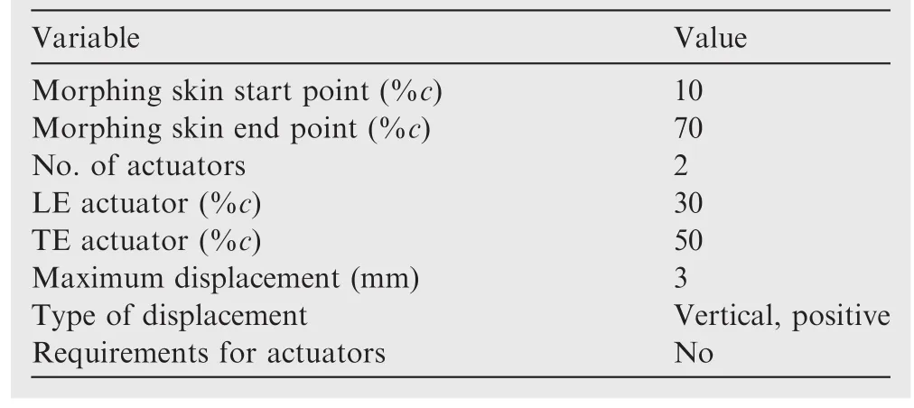
Table 1 Morphing problem variable values for ATR42 wing airfoil.
An additional structural requirement was added to limit the variation in displacement between the two actuators situated on the same rib.This requirement was considered an additional safety measure to those already implemented through the control system to avoid overcharging the morphing surface,and surpassing the maximum allowed force developed by the actuators.Table 2 presents the morphing surface limits,the number and position of the actuators on each rib and the maximum displacements.
The problem of airfoil upper-surface morphing to improve the aerodynamic behavior of wings does not have a single solution.More often,as presented in Section 3 of this paper,there is an optimum region where several possible solutions coexist,and any of them could be considered as the final solution to the problem.
3.3.Genetic algorithm methodology
Based on the problem description in Section 2,the genetic algorithm(GA)was designed to incorporate all variables presented in Tables 1 and 2 in a general manner,in order to easily adapt to different requirements in the projects and to find the optimal solution for the actuator displacements situated on the same rib.This GA could therefore accomplish the given objective of improving the airfoil,and implicitly the wing,aerodynamic behavior.
3.3.1.GA input
The GA allows the user to choose from a number of structural and aerodynamic variables as well as optimization parameters.The input contains all the data needed to control the optimization,from the problem definition to the effective optimization parameters and objectives.
Fig.6 presents the ‘in-house’genetic algorithm internal design and the interactions between the input variables,the aerodynamic solver XFoil and the components of the optimization routine.
Table 3 presents the input blocks and the parameters that were needed for the genetic algorithm to start an optimization.The third column in Table 3 presents the recommended parameter values used to obtain the best convergence speeds and optimization results,for problem of the MDO 505 wing demonstrator morphing upper-surface shape optimization.
A first generation was created based on the maximum actuator displacement and the number of individuals.An individual in a generation is defined by its genes,which corresponds with the actuator displacements for our problem.
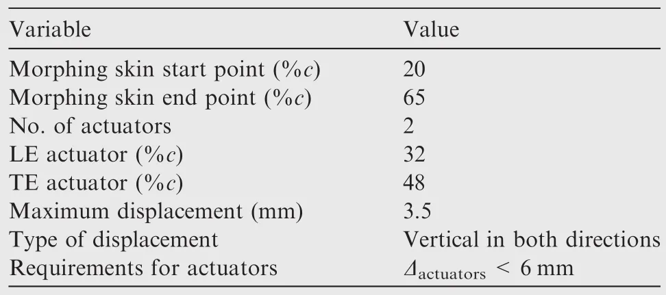
Table 2 Morphing problem variable values for MDO 505 wing demonstrator airfoil.
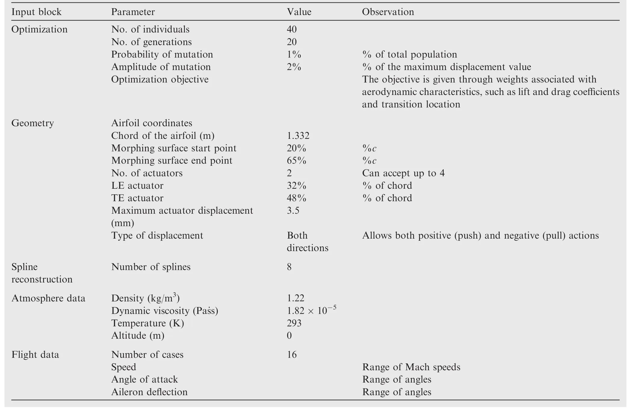
Table 3 Input blocks and parameters for MDO 505 demonstrator airfoil.
3.3.2.Airfoil reconstruction and aerodynamic analysis
In order to analyze the optimization level of each of these individuals,they need to be transformed from displacements to airfoil shapes.The process of reconstructing the airfoils is based on cubic spline interpolation and requires the displacements associated with each individual,the coordinates of the original airfoil,the morphing surface limits,the number and positions of the actuators and the number of spline points.
Spline functions are characterized by their shape on subintervals,between two control points.They are also known as piece-wise polynomial real functions.In interpolation problems,spline interpolation is often referred to as polynomial interpolation,as it yields similar results.With lower-degree splines(such as bi-splines or cubic splines),the resulting curve is rebuilt as accurately as if it had been interpolated with high degree polynomials,but with the benefit of avoiding instability due to Runge’s phenomenon.35,36
The most-used spline interpolation is the cubic spline,which ensures continuity up to the second order derivatives,thus allowing the calculation of the curvature radius.For the problem of the morphing upper surface,cubic splines were found to be sufficiently accurate to reconstruct the wing airfoil shape as function of the actuator displacements.37,38
The reconstructed airfoils were refined and analyzed using the XFoil aerodynamic solver,based on the free stream conditions and the considered flight cases.XFoil is an open source aerodynamic solver developed by Drela39that allows both inviscid and viscous calculation.It also includes the estimation of the boundary layer parameters,including the transition position and function for modifying the airfoil geometry,such as curvature change and flap deflection.
In XFoil,the inviscid calculations were performed using a linear vorticity stream function panel method.A Karman-Tsien compressibility correction40was added to the panel method,which allowed for more accurate predictions in subsonic flow.For the viscous flow calculations,XFoil uses a two-equation lagged dissipation integral boundary layer formulation41and incorporates the eNtransition criterion.42The flow in the boundary layer and in the wake interacts with the inviscid potential flow by using the surface transpiration model.
The XFoil code was chosen because its precision and effectiveness for rapid design and assessment have proven to be acceptable,and because of the code’s rapid convergence.The latter attribute is especially important in an optimization using the genetic algorithm,where a large number of individuals and generations are analyzed simultaneously.
The parameters that resulted from the Xfoil analysis were the lift,drag and moment coefficients,the upper-surface transition point and the skin friction coefficient,a critical parameter for understanding the flow’s boundary layer behavior.
3.3.3.Optimization evaluation
The results of the analysis were integrated into a single point multi-objective fitness function,expressed by Eq.(1),and paired with user-defined weights that must be provided according to the optimization objective desired in the input.
The fitness function calculates a fitness value that estimates the quality level of each analyzed airfoil.The goal of the optimization was to find the airfoil that had the maximum fitness value,and the algorithm was set up in a manner to avoid userdetermined values for this problem.Thus,the algorithm was allowed to search the maximum fitness value across the number of generations introduced in the input block(Table 3).
whereFfrepresents the fitness function,CL,CDand UpTrrepresent the following aerodynamic parameters:lift coefficient,drag coefficient and upper surface transition position.wirepresent weights associated to each section of the function.
When all the airfoils from a generation were analyzed and a fitness value was associated to the corresponding individuals,the individuals were sorted from the highest to the lowest fitness values and awarded grades.Since the fitness value varies from individual to individual, fitness value groups were created and a single grade was associated to each group.For example,if 5 individuals had fitness values between 60 and 65 and these values were the highest in a generation,they would be assigned to one group and all airfoils from this group would be given a grade of 10.
The awarded grades were given values between 1 and 10,with a step of 1,where 1 was the grade given to the group containing the worst individuals and 10 was given to the group containing the best individuals.
3.3.4.New generations and individuals
The main part of the genetic algorithm was the evolution from the current generation towards the next one.Two main processes were used to determine the evolution of a generation:cross-over and mutation.
(1)Cross-over
Cross-over is a process in which two or more individuals are paired and their genes(which were the actuator displacements here)are mixed to obtain a new set of genes which defines a new individual.
For the cross-over process,the parent individuals were randomly selected from the present generation;not all of the individuals had the same chance of being chosen as parents.The individuals with higher grades had more chances to be selected than those with lower grades,thus allowing the best genes to propagate to the next generation without endangering the convergence of the optimization by a minimization of the genetic pool.This particularity of the individual is called the attraction factor,which shows how an individual with a high grade is more attractive and thus more likely to be chosen to become a parent.
A probability function was developed based on the attraction factor and a random value;it gave values between 1 and 10 to individuals,based on which they were chosen to become parents.
wherePsis the probability of selection andAfrepresents the attraction factor,which was set at 2 in the present case.
The cross-over process used in the ‘in-house’genetic algorithm has two step functions,based on the convergence rate observed during tests.It was observed that the algorithm converged towards the optimal region from the first 10 generations(Fig.7)when using a single cross-over function.
However,since there was the possibility that after 10 generations the algorithm would only be situated in the vicinity of the optimal region,instead of finding a solution inside this region,a two-step function was implemented.
The first step is a function that mixes the parents’genes in equal proportions;it was used for the first 10 generations when the algorithm was closed to the solution region.At the tenth generation,the algorithm was switched to use the second function,which was developed based as a variation on a binary cross-over function.43The second function was applied throughout the remainder of the generations until the last generation was reached.
wherei∈ [1,number of genes]i∈ [1,number of genes],j∈ [2,number of parents].
where random δ∈ [0.1],i∈ [1,number of genes],j∈ [2,number of parents].
(2)Mutation
At each generation,after the new individuals were created by cross-over,they were subject to the mutation process.The effect of the mutation depended on the probability of mutation and on the amplitude of each mutation,both parameters being provided in the input by the user.
The probability of mutation dictates the percentage of individuals in a generation that will have their genes affected by the mutation process.For the present problem,the probability of mutation was set at 1%of the number of individuals in a generation.The individuals that would be affected were selected at random from the new generation.
The amplitude of mutation determines the rate with which the genes(displacements)are modified.For the given problem of airfoil upper-surface morphing,where there was a maximum displacement requirement,the amplitude of mutation was set as a percentage of that displacement value,and it was selected to be 2%of the maximum possible displacement.
Both the probability and the amplitude of mutation are sensitive parameters that should be handled with care,because setting a value too low or too high would affect the convergence of the GA or could cause divergence.The uppersurface morphing airfoil problem had a small number of optimization parameters–two actuator displacements–and it was found to be stable;Figs.8–10 present the effects of various combinations of probability and amplitude of mutation on the convergence for this problem.
Fig.8 displays three combinations of the probability of mutationPmwith constant amplitude of mutationA.It can be observed that when thePmwas 0,the convergence was very fast and almost all the individuals reached the optimum region in 5 generations;for the next 9 generations the individuals varied between 2 possible solutions,and starting with the 15th generation they stabilized around a single value.Although this behavior would normally be considered excellent,there was still a high probability that it had found a local optimum in the vicinity of the global one,as there was no perturbation in the genetic pool that would ensure that this was indeed the global optimum.WhenPmwas at 10%,the algorithm also converged towards the optimal region very quickly,but with the 7th generation it started to oscillate between different solutions and did not stabilize even after all the generations had passed.This indicated that to achieve convergence,the algorithm needed a higher number of generations and individuals.The last combination,wherePmis at 1%,also the value recommended for this problem,converged as quickly as the other two combinations,and obtained a stable solution starting with the 14th generation.At generations 16,19 and 20 it searched outside the optimum zone but returned to the same optimum value,confirming that it was indeed in the global optimum area.
Fig.9 shows three combinations of amplitude of mutationAwith constant probability of mutationPm.It can be observed that for this problem,varying the amplitude up to 5%of the maximum displacement value did not affect the convergence in a critical manner.However,whenA=5%of the maximum displacement value,oscillations appeared during the last four generations,which could increase the probability of outputting a local optimum.The effect of high amplitude was observed mainly from the number of times the algorithm had to repeat the process of generating new individuals,as not all of them respected the requirements.This aspect delayed the optimization process,slowing it down and giving it a high rate of divergence because of the lack of individuals that complied with the desired requirements.
Fig.10 presents two extreme combinations ofPmandAthat were compared with the recommended combination given in Table 3.It can be observed that both the extreme combinations of highPm-lowA(Pm=0.1,A=0.5)and highPm-highA(Pm=0.1,A=5)did not converge throughout 21 generations,which implied that for a good convergence they needed more generations and possibly more individuals per generation.
The airfoils that resulted from the cross-over and mutation processes were not guaranteed to respect the requirements;for example,they might have a displacement value higher than the maximum value,or they may not respect the maximum relative displacement value between actuators.Therefore,requirement verification was applied to each new individual,and if they did not comply with the user-defined constraints,the process of selecting parents and applying the cross-over and mutation was repeated until an individual complying with the requirements was found.If after 10,000 iterations no individual was found the optimization was stopped.
If the variations in the probability and amplitude were high enough,the probability that the new airfoils would not comply with the requirements was high and led to a premature end of the optimization.
(3)Tournament
Starting with the second generation of the optimization,a tournament was introduced before the selection of parents for the subsequent generation.The tournament ensured that some airfoils from the previous generation that had good performances(a grade of 8 or higher),were given a new chance at reproducing by replacing some of the worst individuals from the current generation that had very poor performances(a grade of 4 or lower).This form of selection provided a higher chance of converging towards the optimum in fewer generations.
Fig.11 presents the effect of the tournament on the optimization convergence for a test case at a speed of 51 m/s,angle of attack of-4.1°and aileron deflection angle of 1°down.It can be observed that in the absence of the tournament operation,the case converged slowly towards the optimum area(7th generation),and then it continued to oscillate between 2 possible solutions until the final generation.
When the total number of generations was reached,the program produced a file containing the aerodynamic performances of the best airfoil from the previous generation and the aerodynamic performances of the original airfoil on which the optimization was performed.The other result files output by the optimization contained the airfoil coordinates,the pressure coefficient and the skin friction coefficient distributions for the best airfoil shape.
Figs.12 and 13 present the optimization convergence for all the individuals analyzed within each generation,and the convergence of the best individual in each generation,using the parameters provided in Table 3 for a speed 51 m/s,angle of attack-4.1°and aileron deflection 1°.
3.4.GA comparison with two other optimization methods
To ensure that the genetic algorithm found the global optimum for each flight case,twenty cases were analyzed for two fitness objectives:minimization of the drag coef ficient and transition position optimization towards the wing’s trailing edge.The results obtained from these 20 cases test were compared to the results obtained with two other optimization methods:the BC algorithm and the GD method.
The BC algorithm mimics the strategy of honeybees to find the best solution to a problem.The colony’s scouts constantly search for new food sources(a solution of the optimization problem)while the other bees serve as guides.Each time a bee reaches a source,it evaluates the profitability(optimization level)and returns to the hive to communicate the value and location of the source to all onlooker bees.Rich sources have a higher probability of being revisited,and the onlooker bees will search around these rich sources(good solutions).Some of the scouts will also go searching around the rich sources,while others will look for new sources.
Multiple types of BC algorithms44–46were developed by authors,but for this study an ‘in-house’developed version BC algorithm,that considered 30 bees,randomly placed in the displacement constraints(-3.5 mm,3.5 mm)range,was used.One bee represents an airfoil with its corresponding(x1,x2)displacements.The airfoil was analyzed with the Xfoil solver to find the flow transition point on the upper surface or its corresponding drag coefficient.The value of the aerodynamic objective(transition point or drag coefficient)represents the profitability associated with that bee.After communicating the profitability value to the hive,each bee continues to search around the source where it was sent for a given number of cycles.At the end of the searching process,only the source with the best profitability is kept,and all other bees are again randomly placed.Usually,a good result was found after 7 searching cycles.
The gradient descent method is a first-order optimization algorithm.To find a local minimum of a function using gradient descent,steps proportional to the negative value of the gradient(or of the approximate gradient)of that function at the current point are taken.When steps proportional to the positive of the gradient are taken,a local maximum of that function is approached;the procedure is known as gradient ascent.47,48
The search started from the un-morphed airfoil,with(0 mm,0 mm)displacements.At this point,the gradient was calculated using finite differences approximations.The finite differences were calculated so that they gave the direction to find the maximum of the objective function.For the present problem there were two distinct objective functions–minimization of the drag coef ficient and delay of the transition point towards the trailing edge–basically a minimization and a maximization problem.Therefore,the algorithm needed to switch from solving one problem to solving the other problem,as a function of the user input.
In addition to direction tracking,a step was needed to find new displacements.After trying different versions,a step of 1 × 10⁻⁶was chosen in addition to the gradient’s value.The displacements were then modified according to the following equation:
The method converged very quickly,in only a few iterations,but the disadvantage was that it covered a small search area.The algorithm stopped when it found a local minimum,and so the quality of the results was very random and depended upon individualcases.Thisaspectcould beimproved by coupling it with another algorithm such as the BC.This method was also very sensitive to aerodynamic solver convergence as the results were improved gradually.Therefore,if the solver did not converge during the iterative procedure,the calculation of the new gradient value was not possible,with consequences on the optimization process convergence.

Table 4 Flight cases used for comparison test.

Table 5 Description of operating system and type of machine used for tests.
Some results of the three optimization methods were plotted on maps obtained with the Monte Carlo method,that created an envelope of all the displacement combinations for the given fitness objective.The cases for which the results were plotted were Cases 5,8 and 16 from Table 4.Table 4 presents the twenty cases for which the comparison was made.All the aerodynamic analyses were performed using the XFoil solver.
To minimize the amount of time needed to run the optimization process for all twenty cases with all three methods,several computation machines were used.To ensure that no errors were introduced from the type of machine used,various analyses were conducted on five different machine con figurations.It was observed that different operating systems and different machine hardware had a negligible in fluence on the analyses’results.Fig.14 presents a comparison between the flow transition results for all five machines,obtained using the GA optimizer.Table 5 presents details about the five machines on which the tests were done.All the analyses were done for the same atmospheric conditions:density,temperature and air dynamic viscosity at sea level and altitude of 0 m.
For the comparison with the two other optimization methods,the optimization was done for the two fitness objectives:drag coefficient minimization and transition optimization towards the trailing edge.The fitness functions associated with these objectives were derived from Eq.(1)using appropriate weight factors.For the drag coefficient optimization the comparison was done between the genetic algorithm and the bee colony algorithm,and for the transition optimization the comparison was done with all three optimization methods.The comparison results are presented in Figs.15–20.The drag coefficient in the following figures is presented in counts,where one drag count equals to a drag coef ficient value of 10-4.
From Figs.15–17 it can be observed that for three cases,the BC algorithm had found a drag coef ficient smaller than the one found with the GA,and in those cases,the actual difference was less than 1.5 drag counts.Overall,for the objective of minimizing the drag coefficient,the algorithms were considered to give similar results.The few cases where the GA did not score better than the BC could be considered as minor local optimums inside the global optimum area.
The error presented in Fig.20 was calculated as the difference between the GA and the BC transition point results or the difference between the GA and the GD method transition point results,with the results presented as a percentage of the chord.
Figs.18–20 present the results for the transition optimization towards the trailing edge objective for all three methods.It can be observed that the three algorithms gave close results;in some cases,the GA obtained results 4%of the chord better than those of either the BC algorithm or the gradient descent method,with only one case where the bee colony outperformed the genetic algorithm by 2%of the chord.These results confirmed the superiority of the GA in 95%of the cases,for the problem of transition delay.
Figs.21–23 present the Monte Carlo maps with the three algorithms’results for the drag coefficient reduction objective(Case 4)and for the transition delay objective,for Cases 8 and 19(as presented in Table 4).
It was observed that for the problem of upper-surface airfoil morphing,where there are two parameters to optimize,the three optimization methods found the global optimum area in almost all the cases and situated their results inside that region,with the GD method having the lowest quality results.
The Monte Carlo maps show that there was no particular unique solution to the optimization of an airfoil uppersurface,as there was a region in which various combinations of actuator displacements had obtained relatively the same transition point location or drag coefficient value.For any given test case out of the 20 cases,the three algorithms could give three different solutions(where a solution refers to a combination of displacements)located inside the global optimum region.Nonetheless,the genetic algorithm has proven its reliability and that it obtained similar and even better results than the BC algorithm for most of the test cases,therefore it was further used for the optimization of the cases experimentally tested in the CNRC wind tunnel for the morphing wing tip technology demonstrator.
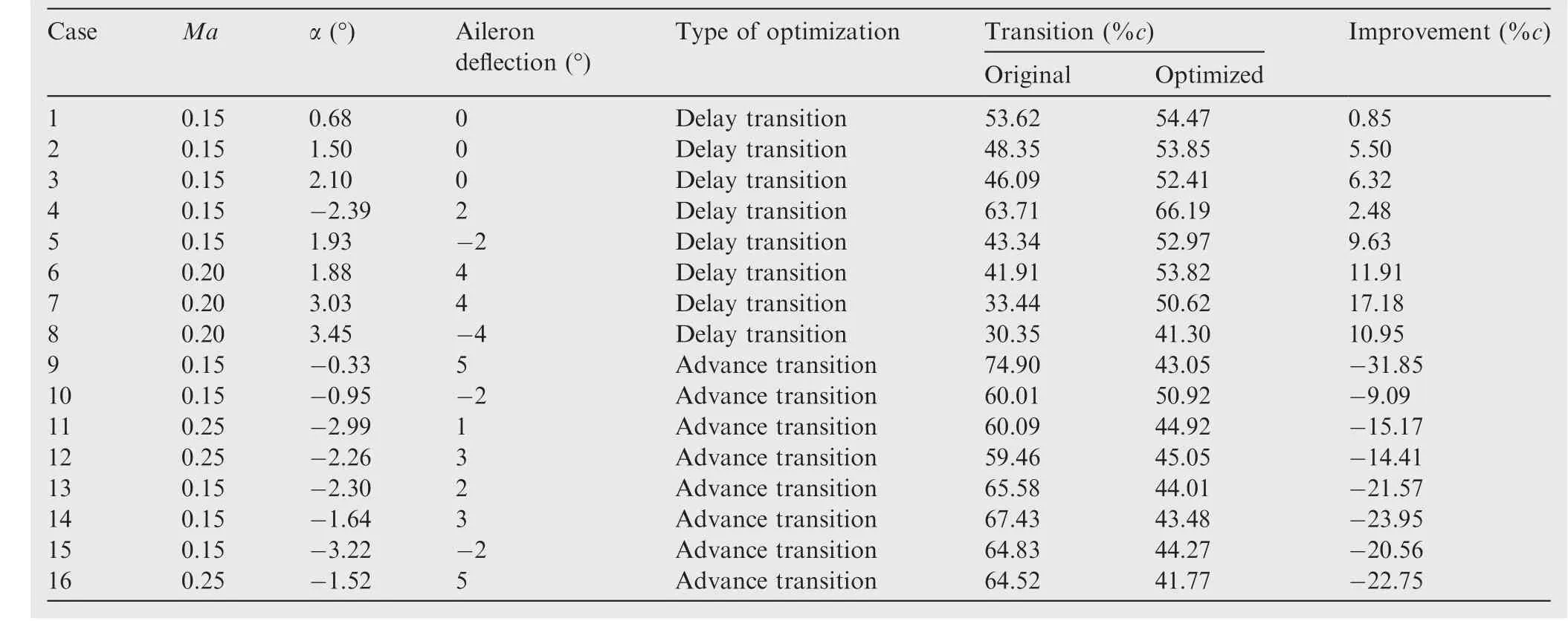
Table 6 Optimization cases and results for wing tip demonstrator.
Table 6 presents the 16 wind tunnel test cases optimized by the GA.Two objectives were considered by influencing the transition from laminar to turbulent flow:delay of the transition towards the trailing edge of the wing(to achieve a reduction in the drag coefficient)and advancement of the transition towards the leading edge of the wing tip demonstrator(to provide a more stable,turbulent flow when the aileron was deflected).
The improvement was calculated as the difference between the transition point obtained for the optimized airfoils and the transition obtained for the original airfoil of the wing tip demonstrator.
Figs.24 and 25 present the visual comparison between the original airfoil transition and the optimized airfoil transition for the two objective functions,using wind tunnel flow conditions and the parameters provided in Table 5.
4.Conclusions
The present paper presents an ‘in-house’genetic algorithm that was applied to the problem of optimizing the shape of the upper surface of an airfoil by using actuator displacements.The method was applied to two different wing airfoils,the ATR42 wing airfoil and the MDO 505 morphing wing demonstrator airfoil,using a multidisciplinary approach in which structural,aerodynamic,control and experimental requirements were combined to configure all the aspects of the optimization.
The genetic algorithm functions were described using the MDO 505 wing’s airfoil configuration.By using the recommended configuration,the algorithm converged towards the optimum region in less than 10 generations,and in 20 generations stabilized itself at the optimum point.The GA was compared to two other optimization methods,the BC algorithm and the GD method,for two optimization objectives:minimization of the drag coefficient and delay of the transition point from laminar towards turbulent flow.These results show that the GA provided similar or better results than the other two methods for most of the cases for which it was tested.By plotting the results on Monte Carlo maps,it was shown that the global optimum area was always reached.
The genetic algorithm was then used to optimize 16 cases for two objectives:delay of the transition towards the trailing edge of the airfoil and advancement of the transition towards the leading edge.The results indicate improvements of up to 17%of the chord for the former(transition delay),and of up to 31%of the chord for the latter(transition advancement).
The displacements resulted from the optimization were used for the upper surface morphing controller during wind tunnel testing on the MDO 505 wing tip demonstrator,and comparisons were conducted between the experimental transition regions of the morphed and un-morphed wing section,using infrared photography.The validation of the numerical optimizations for all the 16 cases is documented in the second part of this paper.
Acknowledgments
We would like to thank Bombardier Aerospace,Thales Canada,the Consortium in Research and Aerospace in Canada(CRIAQ)and the Natural Sciences and Engineering Research Council of Canada(NSERC)for their financial support.Special thanks are due to our collaborators and leaders in this project:Mr.Patrick Germain and Mr.Fassi Kafyeke from Bombardier Aerospace,Mr.Eric Laurendeau from Ecole Polytechnique,Mr.Philippe Molaret from Thales Canada,and Mr.Erik Sherwood and his team from DFS-NRC for the wing model design and fabrication.
1.Xing B,Gao WJ.Innovative computational intelligence:a rough guide to 134 clever algorithms.Switzerland:Springer;2014.
2.Chen T,Wang Y,Li J.Artificial tribe algorithm and its performance analysis.J Softw2012;7(3):651–6.
3.Xie LP,Zeng JC.A global optimization based on physicomimetics framework.Proceedings of the first ACM/SIGEVO summit on genetic and evolutionary computation;2009.p.609–16.
4.Irizarry R.A generalized framework for solving dynamic optimization problems using the artificial chemical process paradigm:applications to particulate processes and discrete dynamic systems.Chem Eng Sci2005;60(21):5663–81.
5.Maniezzo V,Stu¨tzle T,Voß S.Matheuristics:hybridizing metaheuristics and mathematical programming.New York:Springer;2009.
6.Zhang H,Ye D.An artificial bee colony algorithm approach for routing in VLSI.Advances in swarm intelligence.Berlin Heidelberg:Springer;2012.p.334–41.
7.Majhi R,Panda G,Majhi B,Sahoo G.Efficient prediction of stock market indices using adaptive bacterial foraging optimization(ABFO)and BFO based techniques.Expert Syst Appl2009;36(6):10097–104.
8.Cui SY,Wang ZH,Tsai PW,Chang CC,Yue S.Single bitmap block truncation coding of color images using cat swarm optimization.Recent advances in information hiding and applications.Berlin Heidelberg:Springer;2013.p.119–38.
9.Bacanin N.Implementation and performance of an objectoriented software system for cuckoo search algorithm.Int J Math Comput Simul2012;6(1):185–93.
10.Patron RF,Botez RM,Labour D.New altitude optimisation algorithm for the flight management system CMA-9000 improvement on the A310 and L-1011 aircraft.Roy Aeronaut Soc2013;117(1194):787–805.
11.Patro´n F,Salvador R,Kessaci A,Botez RM.Horizontal flight trajectories optimisation for commercial aircraft through a flight management system.Aeronaut J2014;118(1210):1499–518.
12.Gamboa P,Vale J,Lau FJP,Suleman A.Optimization of a morphing wing based on coupled aerodynamic and structural constraints.AIAA J2009;47(9):2087–104.
13.Falca˜o L,Gomes AA,Suleman A.Aero-structural design optimization of a morphing wingtip.J Intell Mater Syst Struct2011;22(10):1113–24.
14.Sugar Gabor O,Koreanschi A,Botez RM.Optimization of an unmanned aerial systems’wing using a flexible skin morphing wing.SAE Int J Aerosp2013;6(1):115–21.
15.Sugar Gabor O,Simon A,Koreanschi A,Botez RM.Improving the UAS-S4 E´hecal airfoil high angles-of-attack performance characteristics using a morphing wing approach.Proceedings of the institution of mechanical engineers,Part G:Journal of Aerospace Engineering2015;230:1–14.
16.Hu TY,Yu XQ.Aerodynamic/stealthy/structural multidisciplinary design optimization of unmanned combat air vehicle.Chin J Aeronaut2009;22(4):380–6.
17.Li PF,Zhang B,Chen YC,Yuan CS,Lin Y.Aerodynamic design methodology for blended wing body transport.Chin J Aeronaut2012;25(4):508–16.
18.Xie CC,Wang L,Yang C,Liu Y.Static aeroelastic analysis of very flexible wings based on non-planar vortex lattice method.Chin J Aeronaut2013;26(3):514–21.
19.Popov AV,Botez RM,Mamou M,Mebarki Y,Jahrhaus B,Khalid M,et al.Drag reduction by improving laminar flows past morphing configurations.AVT-168 NATO symposium on the morphing vehicles;2009.
20.Botez RM,Molaret P,Laurendeau E.Laminar flow control on a research wing project presentation covering a three year period.Canadian aeronautics and space institute annual general meeting;2007.
21.Grigorie TL,Botez RM,Popov AV,Mamou M,Me´barki Y.A hybrid fuzzy logic proportional-integral-derivative and conventional on-off controller for morphing wing actuation using shape memory alloy-Part 1:Morphing system mechanisms and controller architecture design.Aeronaut J2012;116(1179):433–49.
22.Sainmont C,Paraschivoiu I,Coutu D,Brailovski V,Laurendeau E,Mamou M,et al.Boundary layer behaviour on a morphing airfoil:Simulation and wind tunnel tests.CASI AERO’09 conference aerodynamics symposium;2009.
23.Grigorie TL,Botez RM,Popov AV.Design and experimental validation of a control system for a morphing wing.AIAA atmospheric flight mechanics conference Reston AIAA2012.
24.Grigorie LT,Botez RM,Popov AV,Mamou M,Me´barki Y.A new morphing mechanism for a wing using smart actuators controlled by a self-tuning fuzzy logic controller.AIAA centennial of naval aviation forum Reston:AIAA2011.
25.Popov AV,Grigorie LT,Botez RM,Mamou M,Me´barki Y.Real time morphing wing optimization validation using wind-tunnel tests.J Aircraft2010;47(4):1346–55.
26.Popov AV,Grigorie LT,Botez RM,Mamou M,Me´barki Y.Closed-loop control validation of a morphing wing using wind tunnel tests.J Aircraft2010;47(4):1309–17.
27.Sofla AYN,Meguid SA,Tan KT,Yeob WK.Shape morphing of aircraftwing:statusand challenges.MaterDes2010;31(3):1284–92.
28.Vasista S,Tong L,Wong KC.Realization of morphing wings:A multidisciplinary challenge.J Aircraft2012;49(1):11–28.
29.Michaud F.Design and optimization of a composite skin for an adaptive wing[dissertation].Montreal:Ecole de Technologie Superieure(ETS);2014.
30.Herrera F,Lozano M,Verdegay JL.Tackling real-coded genetic algorithms:Operators and tools for behavioural analysis.Artif Intell Rev1998;12(4):265–319.
31.Engelbrecht AP.Computational intelligence:an introduction.New York:John Wiley&Sons;2007.
32.Marwala T.Finite element model updating using computational intelligence techniques:applications to structural dynamics.London:Springer Science&Business Media;2010.
33.Korenschi A,Sugar O,Botez RM.Numerical and experimental validation of a morphed wing geometry using Price-Paı¨doussis wind tunnel testing.Aeronaut J2016;120(1227):757–95.
34.Kammegne MJT,Grigorie LT,Botez RM,Koreanschi A.Design and validation of a position controller in the Price-Paidoussis wind tunnel.IASTED modeling,simulation and control conference;2014.p.17–9.
35.Piegl L,Tiller W.The NURBS book.2nd ed.Berlin Heidelberg:Springer-Verlag;1995.
36.Berbente C,Mitran S,Zancu S.Metode numerice.Romania:Technica Bucharest;1997.
37.Kulfan BM,Bussoletti JE.Fundamental parametric geometry representations for aircraft component shapes.11th AIAA/ISSMO multidisciplinaryanalysisandoptimizationconference.Reston:AIAA;2006.
38.Fincham JHS,Friswell MI.Aerodynamic optimisation of a camber morphing aerofoil.Aerosp Sci Technol2015;43:245–55.
39.Drela M,Youngren D.XFOIL Version 6.96[Internet].2001[cited 2016 Mar 8]Available from:http://web.mit.edu/aeroutil_v1.0/xfoil_doc.txt.
40.Fincham JHS,Friswell MI.Aerodynamic optimisation of a camber morphing aerofoil.Aerospace Science and Technology2015;43:245–55.
41.Drela MARK.Integral boundary layer formulation for blunt trailing edges.Reston:AIAA;1989.Report No.:AIAA-1989-2200.
42.Drela M.Implicit implementation of the full en transition criterion.Reston:AIAA;2003.Report No.:AIAA-2003-4066.
43.Deb K,Agrawal RB.Simulated binary crossover for continuous search space.Complex Syst1994;9(3):1–15.
44.Karaboga D,Basturk B.A powerful and efficient algorithm for numerical function optimization:artificial bee colony(ABC)algorithm.J Global Optim2007;39(3):459–71.
45.Karaboga D,Basturk B.Artificial bee colony(ABC)optimization algorithm for solving constrained optimizationproblems.Foundat Fuzzy Logic Soft Comput2007;789–98.
46.Sugar Gabor O,Simon A,Koreanschi A,Botez RM.Aerodynamic performance improvement of the UAS-S4 E´hecatl morphing airfoil using novel optimization techniques.Proceed Inst Mech Eng G:J Aerosp Eng2016;230:1164–80.
47.Snyman J.Practical mathematical optimization:An introduction to basic optimization theory and classical and new gradient-based algorithms.New York:Springer Science&Business Media;2005.
48.Yuan YX.Step-sizes for the gradient method.AMS IP Stud Adv Math2008;42(2):785.
8 March 2016;revised 13 June 2016;accepted 21 June 2016
Available online 4 January 2017
Ⓒ2017 Chinese Society of Aeronautics and Astronautics.Production and hosting by Elsevier Ltd.This is anopenaccessarticleundertheCCBY-NC-NDlicense(http://creativecommons.org/licenses/by-nc-nd/4.0/).
*Corresponding author.
E-mail addresses:koreanschiandreea@yahoo.com(A.Koreanschi),ruxandra.botez@etsmtl.ca(R.M.Botez).
Peer review under responsibility of Editorial Committee of CJA.
 CHINESE JOURNAL OF AERONAUTICS2017年1期
- CHINESE JOURNAL OF AERONAUTICS的其它文章
- Anti-plane problem of four edge cracks emanating from a square hole in piezoelectric solids
- Stress analysis and damage evolution in individual plies of notched composite laminates subjected to in-plane loads
- Drilling load modeling and validation based on the filling rate of auger flute in planetary sampling
- An adaptive attitude algorithm based on a current statistical model for maneuvering acceleration
- Spacecraft attitude maneuver control using two parallel mounted 3-DOF spherical actuators
- Angular velocity determination of spinning solar sails using only a sun sensor