
Review on monolayer CBN superabrasive wheels for grinding metallic materials
2017-11-21 12:53:30DingWenfengBrrLinkeZhuYejunLiZhengFuYucnSuHonghuXuJiuhu
CHINESE JOURNAL OF AERONAUTICS 2017年1期
Ding Wenfeng,Brr Linke,Zhu Yejun,Li Zheng,Fu Yucn,Su Honghu,Xu Jiuhu
aCollege of Mechanical and Electrical Engineering,Nanjing University of Aeronautics and Astronautics,Nanjing 210016,China
bDepartment of Mechanical and Aerospace Engineering,University of California Davis,Davis,CA 95616,USA
Review on monolayer CBN superabrasive wheels for grinding metallic materials
Ding Wenfenga,*,Barbara Linkeb,Zhu Yejuna,Li Zhenga,Fu Yucana,Su Honghuaa,Xu Jiuhuaa
aCollege of Mechanical and Electrical Engineering,Nanjing University of Aeronautics and Astronautics,Nanjing 210016,China
bDepartment of Mechanical and Aerospace Engineering,University of California Davis,Davis,CA 95616,USA
Brazed;Cubic boron nitride;Electroplated;Grinding;Monolayer superabrasive wheels
A state-of-the-art review on monolayer electroplated and brazed cubic boron nitride(CBN)superabrasive wheels for grinding metallic materials has been provided in this article.The fabrication techniques and mechanisms of the monolayer CBN wheels are discussed.Grain distribution,wheel dressing,wear behavior,and wheel performance are analyzed in detail.Sample applications of monolayer CBN wheel for grinding steels,titanium alloys,and nickel-based superalloys are also provided.Finally,this article highlights opportunities for further investigation of monolayer CBN grinding wheels.
1.Introduction
Monolayer cubic boron nitride(CBN)wheels,including electroplated wheels and brazed wheels,are usually fabricated with a single layer of superabrasive grains that are bonded to a metallic wheel substrate by an electroplated nickel layer or a brazed filler layer,1,2as schematically displayed in Fig.1.3In comparison to the multi-layered CBN wheel types,4,5i.e., resin-bonded wheels, vitrified-bonded wheels and metallic-bonded wheels,monolayer CBN wheels have significant advantages,some of which include good form retention over long grinding times,capability of running at higher removal rates(due to high grain protrusion and large chipstorage spaces6–11),reduction of the complex pre-grinding wheel preparation work(i.e.,periodically dressing and truing operations especially in rough grinding),and possible reapplication of the wheel hub after the grains wear out(such as stripping of the abrasive layer).12,13
In particular,the CBN wheels for high-speed grinding and high-efficiency grinding are usually subject to special requirement regarding resistance to fracture and wear;at the same time,good damping characteristics,high rigidity,and good thermal conductivity are also desirable.7Under such conditions,the grinding wheels are normally required to be composed of a body with high mechanical strength and a comparably thin coating of CBN superabrasives attached tothe body using a high-strength adhesive.The highest cutting speed is only achievable with monolayer CBN wheels,as demonstrated in Fig.2.14
To utilize the advantages of high-speed grinding,in the past decades,the monolayer CBN wheels have been applied more and more in grinding of some important metallic structure materials(i.e.,steels,titanium alloys and nickel-based superalloys)in the automobile and aerospace industries.15–17
This article aims to provide a state-of-the-art review on monolayer CBN wheels for grinding metallic materials,and to offer the authors’viewpoint about some further investigation.For an easy understanding of the relationship between fabrication techniques,grain distribution,dressing techniques,tool wear,grinding simulation,and application techniques,a summarized diagram is firstly demonstrated in Fig.3.
2.Fabrication of monolayer CBN superabrasive wheels
The electroplated CBN wheels and brazed counterparts are both composed of metallic wheel hub,bonding layer and CBN superabrasive grains,as displayed in Fig.1.3The applied metallic material of wheel hub mainly includes AISI 1020 steel,AISI 1045 steel,alloyed steel,and hardened ball bearing steel(100Cr6)18;surely,if the application does not allow for a magnetic material,aluminum or bronze/brass may be also utilized.4Furthermore,the structure design and mechanical machining of the wheel hub are always carried out according to the comprehensive requirements of the machine tools and component profiles.Particularly,for the profile grinding of some critical components(i.e.,aero-engine blade),the size of CBN superabrasive grains must be taken into consideration when designing the particular concave and convex asperities on the circumferential surface of the metallic wheel hub.19The reason is due to the fact that the final profile dimension of the monolayer CBN wheel is completely determined by both the wheel hub and the grain size,as schematically shown in Fig.4.20If either wheel hub or grain size distribution exceeds the desired tolerances,the profile dimension accuracy of the ground components will not meet the desired level.For monolayer wheels,preparing the wheel hub with high strength and high accuracy is not as decisive for the wheel performance as the proper bonding of the CBN grains to the wheel hub.For this reason,this section will focus on the bonding techniques rather than wheel hub preparation.
Usually,the metallic bonds of the monolayer CBN wheels are primarily produced by electroplating and brazing;meanwhile,the electroless plating process is also reported infrequently.4Figs.5 and 6 display the sample morphology and grain protrusion of monolayer electroplated and brazed CBN grinding wheels,respectively.
2.1.Fabrication mechanism of monolayer electroplated CBN wheels
2.1.1.Bonding of CBN grains based on the traditionalelectroplating technique
In most cases,nickel is utilized as the bond material between CBN grains and metallic substrate of the monolayer electroplated wheels.The traditional electroplating technique is based on the cathodic metal deposition behavior from a watery electrolyte.4Generally,fabrication of electroplated CBN wheels may be described as follows23:pretreatment of metallic wheel hub and CBN grains before electroplating;preparation of electroplating solution;spreading and plating the CBN grains on the wheel working surface and then thickening the bond material.During electroplating,the anode consists of the bonding material and the wheel hub acts as cathode.The wheel hub is completely covered with CBN grains and placed into the electrolytic bath.Particularly,the area to be coated is required to be surrounded by a sufficient amount of grains.The electrolytic bath consists of a watery solution of metal salts from the deposited metal,such as Ag,Co,Cu,Ni,Au salts.4The direct current voltage leads to precipitation of Ni at the wheel hub.After the initial bonding of the grains,the excessive grains are removed and the process is continued until the desired plating depth has been arrived.Particularly,the first bonding phase needs a motionless bath,while the second phase of layer growth can work with higher power and bath circulation.4The plating depth leaves about 50%or above of the grain exposed.As an advantage of the electroplating method(also called electrodeposition),no residual stress exists at the bond level due to the low electroplating temperature(such as 60°C or even at room temperature).6,15,24,25However,because of the weak mechanical anchorage between CBN grains and nickel bond,performance of the electroplated CBN wheels can be limited,for instance,by grain dislodgement and even grain pullout from the surrounding nickel bond during highperformance grinding with heavy load,as displayed in Fig.7.15Particularly,the stripping of nickel bond from the wheel hub also becomes a common phenomenon and major deciding factor for shortening the tool service life.In order to improve the bonding strength between the nickel bond and the metallic wheel hub,and finally raise the service life of the electroplated CBN wheels,measures such as heatdiffusion treatment and coating have been applied.
2.1.2.Fe-rich electrodeposition and heat-diffusion treatment
As for the conventional electrodeposition,the Fe-content of the electroplating solution must be reduced to the minimum because it could affect the brittleness of the deposited layer.On the contrary,in the research work carried out by Liu et al.23,Fe-atoms was creatively used by means of FeSO4·7H2O in the electroplating solution.The main purpose included a good leveling-up ability of the electroplating solution,a good softness capability in contrast to the traditional hard-plating Ni,and cost reduction potential due to lower costs of Fe instead of part Ni.After electrodeposition,the heat-diffusion treatment of the electrodeposition layer of CBN wheels was performed in a vacuum stove;as such,the metal composition,especially the Fe atoms,diffused into the metallic wheel substrate.A wide composition-transition-zone was accordingly produced between the bond and wheel hub,and the binding strength was increased greatly.In the grinding process using the electroplated CBN wheels with heat-diffusion treatment,both the machining precision and surface roughness of hardened gear steel were improved effectively.26
2.1.3.Coating of electroplated CBN wheels
Chattopadhyay et al.27,28deposited TiN layer on the electroplated CBN wheels with Ni-bonding(Fig.8).TiN coating was expected to provide twofold benefits15:(a)to render some anti-frictional and anti-wear characteristics in grinding ductile and adhesive metallic material like C-20 low carbon steel and(b)to prevent grain pullout from the nickel bond of the electroplated wheels.The reason for the latter was mainly attributed to the high energy ion impingement of TiN within the electroplated nickel layer coupled with the strong affinity of nickel towards titanium.Under such conditions,a crossdiffusion occurred with the formation of nickel-titanium intermetallic phases up to a certain depth(i.e.,1–1.5 μm)between TiN and nickel.27Because the Ni–Ti intermetallic phase was hard,the scratch resistance of the nickel-bond could be improved during grinding.29At the same time,the enhanced adhesion between nickel and steel substrate avoided grain pullout of the coated CBN wheels in the grinding operations of AISI 52100 hardened bearing steel15;the retention of TiN on the edge and surface of CBN grains also enabled grain fracture during grinding.
Furthermore,Bhaduri et al.22investigated the tribological behavior of MoS2-Ti composite coating with TiN underlayer on electroplated CBN wheels.Compared with TiN coated and uncoated counterparts,the MoS2-Ti composite coating was found to be best performing on nickel in terms of coeff icient of friction and depth of the wear track.In the grinding experiments,a minimum variation in normal grinding force and remarkably steady behavior of the tangential grinding force were obtained with the MoS2-Ti coated CBN wheels.22It should be noted that,there is a potential cost benefit of coating the electroplated CBN wheels for industrial applications;however,this has not yet been discussed or reported.
2.2.Fabrication mechanism of monolayer brazed CBN wheels
As just reviewed in Section 2.1,conventional electroplated CBN wheels usually exhibit random grain distribution,low mechanicalbondstrengthand smallprotrusion ofthe grains.30–33Particularly in some cases of grinding metallic materials,grain pullout can occur and result in early wheel breakdown.MonolayerbrazedCBN wheelshavebeen reported to outperform their electroplated counterparts.9,12,33A precisely controlled brazing technique can build a chemical bridge between CBN grains and metallic wheel hub with the help of an active braze alloy.3Major advantages with the brazed wheels include higher bonding strength to grains,substantially higher exposure of grains measured from the bond level(up to 70–80%of the whole grain height)and flexibility in grain placement in any desired patterns.As such,a large inter-grain chip-accommodation space is created with a tailored grain-distribution pattern,which is essential to avoid premature loading in the grinding operations with high MRR(material removal rate)and to enhance the effectiveness of grinding fluids.3,34
Obtaining reliable joints among CBN grains,brazing filler alloy and metallic wheel hub is an essential problem in the production of monolayer brazed CBN wheels.The interfacial microstructure and chemical resultants at the joining interface are the primary concerns when investigating the brazing techniques of CBN grains.Microstructure and chemical resultants are significantly influenced by the brazing filler alloy,heating method,and heating parameters(especially brazing temperature and dwell time).
2.2.1.Brazing filler alloy
Based on the thermodynamic analysis and physical observations in experiments,Chattopadhyay and Hintermann35discovered that the transition elements of group IV B,such as Ti or Zr,were preferred over the transition elements of group VI B,such as Cr,as activators to promote wetting of the brazing filler alloy towards CBN grains,which are generally far more chemically stable than diamond grains.For example,Ni–Cr alloy,known for effective diamond brazing,failed to show satisfactory wetting and bonding characteristics towards CBN under identical brazing conditions to those of diamond brazing.Meanwhile,wetting and bonding could not be improved either by increasing the Cr content,brazing temperature,or dwell time.35For this reason,direct brazing between CBN grains and metallic wheel hub has been realized through filler alloy containing active transition elements(Ti or Zr).Particularly,Ag–Cu–Ti filler alloy has been utilized broadly owing to its high capillary effect when contacting boron nitride materials12,36and excellent comprehensive mechanical properties(i.e.,Young’s modulus,thermal expansion coefficient and yield strength).However,the cost of Ag–Cu–Ti alloy is usually high due to high Ag content;as such,in the recent years,Cu–Sn–Ti alloy37,38and Cu–Sn–Ni–Ti(or Cu–Ni–Sn–Ti)alloys39were also applied for brazing CBN grains.In order to further improve the filler properties and adjust exposure height of brazed grains,Ding et al.40–42made attempts to add particles of TiN,TiB2,TiC,and graphite into the Ag–Cu–Ti filler powers to prepare the composite filler to braze CBN grains.
2.2.2.Heating method
There are generally four types of heating methods for brazing CBN grains:vacuum resistance furnace heating,laser heating,high-frequency induction heating,and electron beam activated heating.38,43The vacuum resistance furnace heating44and high-frequency induction heating45are the most popular heating methods due to integrated advantages.For example,the vacuum resistance furnace heating is advantageous for the mass production of monolayer brazed CBN wheels;however,it is difficult to control the deformation of the metallic wheel hub for large sizes(for instance,400 mm in diameter).In comparison to the vacuum resistance furnace heating,the high-frequency induction heating method has different advantages,45such as rapid heating rate,locally heating and easy control of wheel deformation.
2.2.3.Heating parameters
Based on the differential thermal analysis(DTA),it is known that the solidi and liquidi of both the above-mentioned Ag–Cu–Ti and Cu–Sn–Ti filler alloys are usually about 780 °C and 820°C,respectively.Accordingly,the brazing temperature is usually set to 880–940 °C37,46for brazing CBN grains.At the same time,the dwell time is chosen at 5–20 min with the vacuum resistance furnace heating method,while it is chosen at only several seconds with the high-frequency induction heating method.45Miab and Hadian47investigated the effects of dwell time on microstructure and mechanical properties of the brazed joints between CBN materials and medium carbon steel(CK45)hub,in which Cusil-ABA(63 wt%Ag,35 wt%Cu and 2 wt%Ti)was utilized as an active filler alloy.The brazing temperature was kept at 920°C.With increasing the dwell time from 5 min to 15 min,the interfacial reaction layers between CBN and filler become thicker and more continuous,resulting in a higher joint strength(such as the maximum shear strength of 129 MPa).47Ding et al.37also discussed the interfacial microstructure and chemical resultants in brazing CBN grains with different dwell time,and the brazing parameters were finally optimized based on the integrated consideration of themechanicalstrength,wearresistance,and grinding performance.
2.2.4.Formation mechanism of interfacial microstructure and chemical resultants in brazed CBN grains
In order to detect the formation mechanism of interfacial microstructure and chemical resultants in brazed CBN grains,experiments of joining CBN grains and a metallic wheel hub using different filler alloys have been carried out.44Different heating parameters and heating methods with high vacuum condition or under argon gas protection were investigated.
Pobol et al.38studied the physical and chemical phenomena which occurred at the CBN-filler interface during electron beam brazing.Wettability was investigated by the contact angles of multicomponent adhesion-active Cu-based alloys on CBN and steel.In addition,the distribution of chemical elements at the CBN-filler interface was examined.At the same time,Elsener et al.48investigated the role of Cu-based active brazing filler composition on its microstructure and properties with the purpose of brazing CBN grains.Furthermore,Ding et al.44,49discussed the effects of the Ti content of Ag–Cu–Ti alloy on the interface microstructure in brazed CBN grains.It was reported that Ti in the filler concentrated preferentially on the grain surface(Fig.9),which generated the needlelike Ti–N and Ti–B compounds layer by means of chemical interaction between Ti,N and B at elevated temperatures.
Based on an investigation into the solid diffusion reaction of pure Ti and BN materials,Ma et al.50discovered that the formation sequence of different resultants in the Ti/BN diffusion couples were mainly dominated by the relative amounts and distribution of the correlated Ti,B and N elements.Furthermore,Faran et al.51,52pointed out that the chemical resultants produced at the Ti/BN interface consisted of the inner layer of fine Ti borides(TiB2,TiB)and the outer layer containing Ti and N.Ding et al.44,49also discussed the formation process and morphology of the brazing resultants between CBN grains and Ag–Cu–Ti alloy,which has been identified as TiB2,TiB and TiN,respectively,as shown in Fig.10.Specially,based on the thermodynamic and kinetic analysis,53,54TiN was found to play a dominating role in controlling the growth of resultants layer during brazing.
Furthermore,the delamination microstructure across the brazing interface of CBN grain and Ag–Cu–Ti alloy was characterized as CBN/TiB2/TiB/TiN/alloy containing Ti,as displayed in Figs.10 and 11.49Under these conditions,the different thermal expansion coefficients of the several brazing resultants have to be considered.For example,the average coefficients of thermal expansion of CBN,TiB2,TiB,and TiN are5.6×10-6K-1,7.8×10-6K-1,8.6×10-6K-1,and 9.35 × 10⁻⁶K-1,55–61respectively.This gradual transition of thermal expansion coefficients reduces the residual thermal stresses at the brazing interface and minimizes potential thermaldamage ofbrazed CBN grains,as verified by experiments.49
2.2.5.Indirect brazing of coated CBN grains
Besides the abovementioned direct brazing with the fillers containing active Ti or Zr,indirect brazing of the metallic coated CBN grains may be realized using the Ni–Cr filler alloy.Grain coating is applied by various techniques,such as chemical vapor deposition,physical vapor deposition,electroless coating,electrolytic wet chemical methods,or dry deposition.4Moreover,several layers can be applied sequentially,for instance,the grain was coated with Ti layer by electroplating,then a Ni-coating was applied by electroplating.Under such conditions,dependent on the reaction of CBN-Ti and Tifiller(such as Ni–Cr alloy),the CBN grains could be also bonded chemically to the wheel hubs.However,indirect brazing of CBN grains is not commonly utilized in the present days.In general,grain coating is applied for various reasons,such as grain retention in the bonding,grain protection,grain alignment,or heat transfer during the manufacturing/application process of the grinding wheels.4
3.Grain distribution on the working surface of monolayer CBN wheels
During the grinding process,numerous grains interact with the workpiece material producing mechanical and thermal loads on the machined surface.62Linke63has summarized the most important grain properties and their main impacts on the wheel performance,as listed in Table 1.Particularly,the stochastic geometry,dimension and distribution of the grains on the working surface of monolayer CBN wheels,can cause irregular grain protrusion,which limits the material removal rates and workpiece surface quality generated during grinding.64,65The main reason is the variation of the resulting uncut chip thickness per single grain,which yields undesirable side effects.For example,the friction behavior of a single grain with very low uncut chip thickness increases the heat generation in the grinding process;however,a single grain with very high uncut chip thickness is stressed by high grinding forces,which potentially leads to grain breakout.Therefore,it is important to prepare the monolayer CBN wheels with a controllable and homogeneous grain distribution pattern,to controlthe toolgrinding performance,force and power requirement,loading,grain wear and grain pullout.33
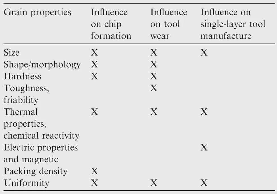
Table 1 Grain properties and affected tool life stages.63
3.1.Grain geometry and dimension
Usually,a precise analysis of the material removal mechanisms in grinding is very complicated because the contact zone is inaccessible for measurements,the abrasive grains are randomly distributed,and grain geometry and dimensions are stochastic.66A comprehensive understanding of the single grain interaction enables to synthesize the material removal mechanism of a grinding wheel from the contribution of each single grain.67
Morphology of CBN grain crystal can vary between cubic and octahedral like diamond and between octahedral and tetrahedral.68Based on this understanding,Schumann et al.62modeled the ideal shape of CBN grains as the intersection of hexahedron,octahedron and tetrahedron based on the constructive solid geometry technique.He also modeled diamond grains which miss the tetrahedron shape.By scaling these primitives appropriately,different geometries and dimensions were generated.Several simulated grains,which were identified using a pair of index values,are shown in Fig.12.Meanwhile,Opoz and Chen66recently investigated the removal mechanism and scratch topography using CBN grains.Similar research work on grain shape was also carried out by Li et al.69,who simulated the grinding wheel numerically with discontinuous structure using discrete element method.
Additionally,Transchel et al.67conducted an experimental study of single grain grinding operations using varying orientations of blunt,octahedral shaped diamonds,the results of which could be also transferred to CBN grains.It was found that,the position of the flank face defined by the corresponding clearance angle towards the grinding direction,has a significant influence on the material removal mechanism and associated grinding force ratio.Positive clearance angles orthogonal to the grinding direction usually favor the material removal towards a higher efficiency.
Furthermore,the grain dimension and its distribution on CBN wheels need to be controlled strictly.Generally,a small grain size commonly achieves smaller surface roughness,but also causes higher grinding forces and shorter tool life.63At the same time,the unavoidable distribution of grain size in monolayer CBN grinding wheels is one reason for touchdressing,which can equalize the highest cutting edges and maintain a predictable part surface quality.70Under such conditions,understanding the correlation between grain dimension deviation and wheel performance is critical,and the first step to gain this knowledge is to correlate the relevant wheel design parameters with the wheel topographical features.Rong et al.71established the through-the-process model for singlelayer electroplated CBN wheels by simulating each wheel fabrication procedure numerically.Capacity of this model was verified by comparing simulation results with the experimental measurement data in terms of the static grain count and grain protrusion height distribution.Furthermore,the intrinsic relationship between the grain dimensional distribution and the wheel surface topographical properties was also analyzed.The ‘digital’wheel bears sufficient resemblance with the real products,and the through-the-process model of grinding wheels is capable to predict the micro-topographical features of the electroplated CBN wheels,such as the static cutting edge count and the protrusion height.
3.2.Structured CBN wheels
In grinding industry community,the surface functionalization of grinding wheels by introducing pre-engineered textures or structure is a recognized approach to reduce the grinding temperature or the grinding force,and help the chip removal.72For example,Rabiey et al.73developed a structured electroplated CBN wheel for dry grinding of metallic materials,in which defined clusters or islands of grains were fabricated,as shown in Fig.13.The new macro-topography of the wheel reduced the actual contact area to only 22%of the conventional contact area between wheel and workpiece.With this structured wheel,the average uncut chip thickness was increased,which decreased the specific grinding energy and tangential grinding forces.73,74The total heat generated in the contact zone was accordingly reduced greatly,which also reduced the heat transferred to the workpiece and therefore decreased the grinding temperature.In addition,enough space was provided for the chips to be carried away in the empty space on the surface structure,reducing wheel loading and rubbing between chips and workpiece surface in comparison to the conventional wheels.
Patterned surface structures on grinding wheels can also be produced by dressing.75Tawakoli et al.76generated different wheel-structure patterns using the dressing tool,as displayed in Fig.14.The contact area between wheel and workpiece was reduced by removing portions of the wheel surface with the dressing roller;simultaneously,recesses were created on the wheel surface which made canals for coolant or air flow on one side and created relatively bigger chip pockets on the other side.77–79Mohamed et al.80developed grooved grinding wheels made by dressing,as displayed in Fig.15.In creep-feed grinding experiments,the grooved wheels not only removed twice as much material as a non-grooved wheel before workpiece burn occurred,but also improved the grinding efficiency by reducing the consumed power by up to 61%.Oliveira et al.81also presented a dressing technique that allowed the inscription of pre-configurable patterns,or textures,on the grinding wheel surface,which increased the grinding performance in conventional applications.Generally,the combination of the dressing depth,dressing velocity and the dressing tool tip geometry determined the wheel topography characteristic.By control-ling these parameters,the desirable wheel sharpness can be obtained to ensure the best grinding performance.
Likewise,Gao et al.82developed an electroplated CBN wheel with controlled abrasive clusters in specific patterns,as shown in Fig.16.The maximum dimension of clusters was 0.2–1.0 mm and the interspace between them was about 0.5–1.0 mm.Compared with the conventional electroplated CBN wheels,the grinding forces of these new wheels were always lower,and the wheel loading phenomenon was markedly decreased.Walter et al.83developed a picosecond pulsed laser structuring method to produce various micro patterns on the surface of CBN wheels.This method allowed for fabrication of arbitrary surface structures,enabling a high degree of geometrical and dimensional control of the produced features and thus of the grinding performance of CBN wheels.84Moreover,the thermal impact of picosecond laser processing on the CBN abrasive grains can be neglected according to Walter et al.83,84.
In recent years,theoretical analyses were also carried out on the above-mentioned structured wheels.For example,Aslan et al.85developed a thermo-mechanical model to predict forces in grinding with circumferentially grooved and regular(non-grooved)wheels.Good agreement was obtained between the theoretical results and the experimental data.As a disadvantage of the structured wheel from a quality point of view,the decreased contact layer between wheel and workpiece usually produces a rough ground surface.At present,this problem has been solved effectively by increasing the process time by following the rough grinding pass with one fine grinding pass.73,76,80,83
3.3.Defined grain distribution
Besides the grain dimension and layer structures,grain distribution is another important parameter to define the topography of monolayer CBN wheels.73Ghosh and Chattopadhyay6prepared brazed wheels with three types of grain distribution patterns,i.e.regular distribution(RD),densely packed distribution(DP),and helical distribution(HEL),as schematically shown in Fig.17.The transverse finish produced by the DP wheels before dressing is better than that produced by the other two types of wheels,because they have a higher density of active grains leading to increased overlapping-cuts of active grains during grinding.Furthermore,the performance of HEL wheels after touch-dressing was found to be the best because they produced good finish comparable with that produced by DP wheels,and simultaneously they also offered larger inter-grain chip space.6
Likewise,Aurich et al.64developed electroplated CBN wheels with defined grain patterns to reach a homogeneous grain protrusion in conjunction with a huge chip space volume so as to improve process stability.Different grain distribution patterns were designed by means of kinematic simulation with special focus on the uncut chip thickness,86–88as shown in Fig.18.A ratio of 1.13 of the long-and short-grain axis and a ratio of 3:1 of cubic and tetrahedral basic grain geometry was modeled.A protrusion height of 35%of the grain size was taken;for instance,the average grain protrusion height was 107 μm for an average short grain axis length of 305 μm and a standard deviation of 30 μm.Based on the simulation results,a prototype grinding wheel with an optimized defined grain structure was constructed,as shown in Figs.19 an d 20.86,89The grinding performance of the prototype wheel was also validated in dry grinding experiments of hardened heat-treated steel 42CrMo4V(DIN EN 10132-3)with a material removal rate of 70 mm3/mm·s.Generally,the prototype wheel showed better performance,such as lower grinding forces and power and lower grinding temperature,than the traditional wheel with random grain distribution.90,91Similar work for the defined grain distribution of monolayer CBN wheels was also reported by Burkhard et al.92and Ding et al.18.
Phyllotaxis is defined as a geometrical and dynamic system generated by biological organisms.93Most of the arrangements of biological structures,such as leaves,seeds of fruit,and petals of plants,conform to the rule of phyllotaxis.Based on the phyllotaxis theory of biology,Wang et al.94–96developed a grinding wheel with phyllotactic pattern,fabricated with lithography mask electroplating technology,as displayed in Fig.21.Furthermore,Wang et al.analyzed not only the relationship model between the phyllotactic coefficient and ground surface roughness,but also established a model of dynamic cutting point density.Compared with the wheel with the conventional stochastic grain patterns,the wheel with the abrasive phyllotactic pattern usually produced better surface roughness in the grinding experiments.96
In theory,the topography of grinding wheels and the grinding forces per active grain provide the basic understanding of grinding edges and workpiece interaction,which is very important to the modeling,planning,and optimization of the grinding process as a whole.Hecker et al.97presented a three-dimensional(3D)analysis of the grinding wheel topography to evaluate static parameters from the wheel surface,such as the effective grain dimension and the static grain density as function of the radial distance from the wheel surface.The dynamic grain density was deduced from the static grain density while considering the kinematic effects(such as the shadows generated by active grains)and the dynamic effects(such as the local grain deflection).These effects were evaluated analytically using the grain depth of engagement and the normal force developed per grain.At the same time,a probabilistic model that estimated the uncut chip thickness was also used to calculate the kinematic and dynamic effects.97This model was calibrated and validated based on experimental data of total normal and tangential forces in surface grinding.Different grain patterns,based on geometric models,were also investigated by means of kinematic simulation64to predict the workpiece surface generated during grinding with electroplated CBN and diamond wheels.87,98,99
4.Dressing of monolayer CBN wheels
Usually,it is not necessary to periodically true or dress the monolayer electroplated or brazed CBN wheels in rough grinding.However,as for the precision grinding operation,because the electroplated wheels as well as the brazed wheels possess an inherent weakness of having unequal distance of the grain tips from the wheel hub surface100,certain percentage of the grains always remains over-protruded,which does not allow the lower grains to participate.6,101For example,Ding et al.102established the normal distribution function of the protrusion height of the CBN grains on the original brazed wheel surface,P(x),which has been described as follows:
wherexis the actual protrusion height of each grain,while μ is the average protrusion height,σ is the standard deviation.
For grains with 80/100 US mesh,the average grain size and the standard deviation were 171.0 μm and 16.74 μm,respectively,while the protrusion height of the brazed CBN grains and the corresponding standard deviation were 112.9 μm and 18.20 μm,respectively,as shown in Fig.22.102Under such conditions,the monolayer CBN wheels without dressing can result in few overlapping cuts of grains in precision grinding,which would lead to a surface roughness,measured in the transverse direction,substantially higher than the acceptable value.Particularly,absence of any crossfeed during profile grinding greatly worsens the situation.Additionally,the performance of monolayer wheels also varies due to wheel wear through the wheellife,which degradesthe workpiece quality uncontrollably.13,73
In recent years,the problem of high workpiece surface roughness associated with application of monolayer CBN wheels has been solved by mechanical touch-dressing,as demonstrated in Fig.23.6,103Although electroplated CBN wheels are not considered to be dressed in the conventional sense,the resultant workpiece surface roughness can nevertheless be influenced within narrow limits by means of the touchdressing process.This involves removing the peripheral grain tips by means of very small dressing infeed steps in the range of dressing depths of cut between 2 and 4 μm,thereby reducing the effective roughness of the grinding wheel.7In general,a rotary diamond dresser can be also used to touch-dress monolayer CBN wheels.
In one example application,the dressing tool was a block with synthetic diamonds brazed on its top flat face,and tips of the diamond particles(D91,90/75 μm mesh width)were made intentionally dull.Gradual touch-dressing of CBN wheels can improve the roughness of the ground surface.70It was found that the required cumulative depth of dressing was dependent on the size of CBN grains.The touch-dressed wheel not only reduced the ground surface roughness greatly but also maintained an almost constant roughness value over a long span of grinding.In particular,after touch-dressing,a wheel with helical grain distribution produced a finish(aboutRa=1 μm)close to the one produced with densely packed grain distribution;whereas,the wheel with regular grain distribution finally produced a surface roughness ofRa=1.5 μm.
Warhanek et al.104presented a laser dressing process which enabled the generation of positive clearance angles on stochastic grain surface of the monolayer electroplated diamond abrasive tools,as displayed in Fig.24.As such,the problems caused by near-zero or negative angles at the micro-cutting edges could be solved.This method may be also utilized on monolayer CBN wheels.The generation of clearance on superabrasive wheels was a promising complement to existing tool conditioning processes.The dressing time was more than halved by the laser process in comparison to the conventional mechanical touch-dressing process.
5.Wear of monolayer CBN wheels
As well known,because the CBN wheel performance would change gradually due to wheel wear through the wheel life,13wear of CBN grains is always one of the key issues influencing the grinding process and the resulting workpiece quality.17,89,105–110In recent years,much investigation has been carried out on wear of monolayer CBN wheels.
5.1.Wear behavior and mechanism of monolayer electroplated CBN wheels
5.1.1.Wear behavior of monolayer electroplated CBN wheels
Literature has discussed four general wheel wear behaviors and mechanisms:grain surface layer wear,grain splintering,grain-bond-interface wear,and bond wear.111Particularly,Ghosh and Chattopadhyay3proposed possible failure patterns of CBN grains in electroplated wheels,as displayed schematically in Fig.25.Because the process temperature in electroplating is very low,no residual stress exists at the bond level;as such,the grain failure occurs mainly due to lack of mechanical anchorage and crystallographic defects.In the case of low level of plating,grain pullout from the encapsulation of the Nibond easily happens(Fig.25(a)).On the contrary,in the case of high level of plating,the grain failure is decided by the defect structure of CBN grains.Any defect near the bond level is the most detrimental factor because a sudden variation of stress taking place at the bond level or within the bond layer under the grinding load can lead to grain breakage at or from the bond level(Fig.25(b)).Otherwise,mostly the damage takes place much higher above the bond level.3The additional coating on the electroplated wheel surface also has a significant influence on the grain fracture.For example,Bhaduri and Chattopadhyay15have found that the uncoated wheel produced fracture wear during grinding low carbon steel(AISI 1020)and hardened bearing steel(AISI 52100),while the grain fracture was remarkably absent in the TiN coated wheel.The reason is mainly attributed to the resultant compressive stresses in the CBN grains during coating and a better heat transportation capacity in grinding.
In the actual grinding operation,besides the grain pullout and grain fracture,attrition wear is also an important failure pattern for CBN grains.Attrition wear causes an increase in the active grain density and leads to wheel dulling.13,21Dulling of the grain tips by attrition and fine scale grain fracture(fragmentation)resulted in an increase in the grinding power and grinding temperature,and even led to various types of thermal damage to the workpiece of metallic materials.112Selfsharpening by grain fracture is commonly important to moderate the forces in grinding.
Rong et al.113proposed four types of CBN-bond failure patterns in electroplated wheels in the grinding process,as visualized from experiments in Fig.26:①the attrition wear of the grain,where a wear flat area is created on the grain tip;②the chipping of the grain cumulated by small breakage from the grain tip,③the grain dislodgement,referring to CBN grains being totally removed from out of the bonding layer with potentially minor leftovers;and finally④the bond erosion behind CBN grain in the direction of the grinding process.The removal of bonding material was expected to weaken the stability of CBN grain and may in consequence allow grain displacements leading to reduced process accuracy and total grain break outs.
Furthermore,in order to analyze the wear behavior taking into account the grain type and plating thickness,Upadhyaya and Fiecoat2carried out creep-feed grinding experiments of 440 stainless steel workpieces(54 HRC)using electroplated CBN wheels(mesh size 60/70,FEPA B251).The wheels containing tougher CBN grains generally exhibited less wear and a higher G-ratio,and also required less power2;in addition,less wear and higher G-ratio were also obtained for wheels with a thinner layer of nickel plating despite an increased tendency for large-scale grain loss.This would indicate that the overall wheel wear depended more on grain exposure than on active grain density;grain exposure facilitates chip removal and grinding fluid access.114
Based on the grinding experiments of AISI 52100 hardened bearing steel(HRC 62)and B-1900 nickel-based superalloy,Shi and Malkin13,21made an investigation on how the wear process affected the whole electroplated wheel topography,as displayed in Fig.27.112The radial wheel wear was quantitatively characterized in each case by an initial transient at a progressively decreasing rate to a steady-state wear regime at a nearly constant rate until the end of wheel life,which occurred when the radial wear reached 70%–80%of the grain dimension.The wheel wear during the initial transient was mainly due to pullout of the most protruding and weakly held grains(accounting for 60%–80%of the initial transient wear with the rest mainly due to grain fracture),and the radial wheel wear in the steady state regime was dominated by grain fracture.Particularly,the wheel wear was accompanied by a progressive increase in the active grain density and a corresponding decrease in surface roughness.The uncut chip thickness showed a direct and great effect on the wear rate in the steady-state regime for various grinding conditions and grain sizes.21Furthermore,Upadhyaya and Malkin112also found that water-based fluids caused much more rapid wear than straight oils;additionally,the workpiece material also had a big effect on the wear rate,for example,nickel-based superalloy caused much more rapid wheel wear than ferrous materials.
5.1.2.Wear mechanism of monolayer electroplated CBN wheelsRong et al.113investigated the failure mechanism of bonding layer of electroplated CBN wheels from the viewpoints of bonding force.The experimental setup similar to an inclined thread turning process was designed to observe and measure the failure and maximum bonding force of the electroplated layer,respectively,as displayed in Fig.28.113Particularly,one single grain with an average diameter of 300 μm was placed on a tool holder to eliminate the influences of various grains on each and focus on the bonding behavior.Four levels of bonding layer thickness,i.e.50,100,150 μm and 200 μm,were applied,respectively.It was found that the factors that contributed to the maximum bonding force of the electroplated CBN grain could be grouped into three categories:grain properties,bond properties,and the operation conditions,as indicated in Fig.29.115The bonding layer thickness with a maximum of 150 μm had a limited influence on the absolute value of the bonding force as a result of mechanical and thermal actors.113A significant influence was determined for the length of cut required for the grain to be broken off as well as for the grain morphology and orientation.Based on the correlation of the bonding force and wear mechanism,a regime to discriminate grain pullout and sliding was established.
Rong et al.115also established a finite element model(FEM)of single electroplated CBN grains for quantitative analysis of the bonding force,as displayed in Fig.30.A comprehensive correlation between the bonding force and the bonding layer thickness and grain orientation was established through response surface methodology.It was found that a maximum bonding force of up to 60 N was achieved at certain grain orientations.In addition,some suggestions were also provided to develop monolayer electroplated CBN wheels without grain dislodgement.For example,the grain should be as sharp as possible and moreover the sharp corner should be located towards the cutting direction,thus allowing the grain to remain in a stable position as long as possible even though bond erosion weakens the stability and therewith increases the likelihood of the grain to break out.Zhou et al.116also carried out similar simulation work to investigate grain pullout under given mechanical loads and grain geometry.
For wear only by attrition behavior,Upadhyaya and Malkin112have found that the active grain density,C(w),can be written in terms of the radial wear as
wherewwas the radial wear depth;C0was the aerial packing density,which was measured from a scanning electron microscope photography of the new wheel surface.F(w)was the normal distribution function given by112
wherexmaxwas the maximum grain height;mxwas the mean value of the normal curve distribution of the grain height distribution,andswas the corresponding standard deviation.
The theoretical active grain density during grinding can be calculated when taking all of the factors mentioned into accounts.An example was provided in Fig.31.112Here the grain size was 120 US mesh with a mean grain size of 64 μm and standard deviation of 21.3 μm.
Yu et al.117presented a life expectancy model for electroplated CBN wheels,based on non-uniform spatial distribution of grain wear and as a function of the grinding parameters,grinding wheel geometry and topography,workpiece material properties,etc.At the same time,this model was also based on grain pullout,wear mechanism,and the associated state of grain damage.Single grain pullout experiments were conducted to assess the residual strength of the grain-wheel interface and the associated state of damage percolation.
5.2.Wear behavior and mechanism of monolayer brazed CBN wheels
5.2.1.Wear behavior of monolayer brazed CBN wheels
As for the monolayer brazed CBN wheels(Fig.32(a)),the possible failure patterns of grains are illustrated in Fig.32(b).3Particularly,the grain pullout and shear of bond perhaps takes place due to poor wettability of improper brazing alloy(such as Ni–Cr alloy)on CBN grain surface,or lack in strength in the alloy itself.Surely,when the appropriate brazing fillers(such as Ag–Cu–Ti alloy and Cu–Sn–Ti alloy,both of which have good wettability on the CBN grain surface)are applied,grain pullout seldom occurs in the grinding practice.18,102Additionally,partial breakage of grains(micro-fracture)may be confined at tips due to presence of undesirable crystallographic defects inside the grain.Grain macro-fracture can also happen at the bond level3due to the large brazing-induced residual tensile stresses at the junction region,the formation reason of which is mainly attributed to the substantial difference in the Young’s modulus and thermal expansion coeff icients of the brazing filler alloy,CBN grains and metallic wheel hub.Particularly,in grain fracture,cracks are initiated from any defect in the grain near the bond level and propagate along the bond level through grain crystal-defects.
Furthermore,Ding et al.102provided the variation of protrusion height of the brazed CBN grains with 80/100 US mesh in grinding experiments of K424 nickel-based superalloy,as displayed in Fig.33.The wear tendency of the brazed wheels was generally similar to that of electroplated wheels.The causes of three wear patterns,such as grain micro-fracture,grain macro-fracture,and attrition wear,were also similar to that of electroplated wheels.A great difference was that grain pullout did not happen in the tested conditions.
5.2.2.Wear mechanism of monolayer brazed CBN wheels
Similar to electroplated wheels as reviewed before,brazed CBN wheels benefit from strong metallic joining,in this case by brazing and an additional Ag–Cu–Ti bonding,which improves significantly the resistance to grain pullout.102The brazed grains were generally prone to breakage at the bond level under high load conditions,leaving a part of the grain firmly integrated in the encapsulation of the bond(i.e.the brazing alloy).3This kind of premature failure of the brazed CBN wheel seriously affects its grinding capability.Because the active brazing of CBN grains requires high heating temperature and a very protective environment or high vacuum,a substantial imbalance in the thermal strain rates of the metallic wheel hub,brazing filler alloy,and CBN grains is unavoidable during the cooling stage.3As a consequence,residual thermal stress is produced in the joint.Such brazing-induced residual stresses,coupled with the grinding-induced stresses,are found to be the detrimental factor resulting in grain fracture during grinding.
Based on finite element simulation,Ding et al.118–120investigated the grain facture from the viewpoint of the resultant stress evolution in the brazed CBN grain for six wear stages during grinding,as listed in Table 2.Additionally,a discussion was also carried out on the effects of grain embedding depth,grain wear,bond wear,grain size,and grinding load on the stress distribution.119With advancing grain and bond wear,the effect of grinding force-induced stresses was generally weak in the grain bottom,while the corresponding effect of the brazing-induced stresses was significant.Large magnitudes of resultant compressive stresses ranging from-754 MPa to-1243 MPa were produced in the grain vertex region and were the primary factor for grain micro-fracture during grinding.In general,grain wear should be minimized,but certain microfracture in the vertex region of a grain can enhance the sharpness of a grinding wheel.Large brazing-induced tensile stresses were obtained in the grain-bond junction region,which resulted in macro-fracture of the brazed grains at the bond level and reduced the wheel life significantly during grinding.
Furthermore,Ding et al.102found that,though the workpiece material temperature in the grinding zone was merely about 180°C during creep-feed grinding of K424 nickelbased superalloy with a brazed CBN wheel,the grinding heat still had an important effect on grain wear behavior owing to the high temperature of the individual grain up to 500–600 °C.
5.3.Detecting techniques and quantitative characterization of wheel wear
The techniques of detecting the wheel wear can be generally divided into two groups:contact measurement and noncontact measurement.17,110One of the main problems in directly measuring wear of CBN grains is their small size,which makes this task rather difficult.The most representative contact measurement technique is the stylus profilometer,which uses a needle in contact with the surface to be measured.Another contactbased measuring technique is the analysis of imprints generated by the grinding wheel surface after pushing it against carbon paper;however,this technique is generally used to calculate the number of grains but rarely measure the size of wear flats due to its low precision.As a general approach,the use of replicas of the wheel(made with clay,plastic,or similar)is used a lot in research settings as it avoids wheel dismountingorbreakage.121However,itmightintroduce further uncertainty on the measurement.The noncontact measurement approaches applied include optical macroscopy,optical microscopy,confocal profilometry,and scanning electron microscopy(SEM),and structured-light 3D scanner.According to the research carried out by Puerto et al.17,the optical microscopy technique could offer the best trade-off between time and accurate results and even allows a pseudoautomatization of the measuring process for the CBN wheel.
Particularly,the complex changes in cutting edge shape can be evaluated quantitatively using the fractal dimension,which has been applied by Ichida et al.122and Ding et al.123to quantitatively evaluate the micro fracture behavior of CBN grains.First,a reconstruction model of grain topography was established through photographs taken with three-dimensional(3D)optical video microscope.Then the relationship between 3D fractal dimension and the complicated topography change of the abrasive grains was investigated.The fractal dimension of 3D surface profiles of cutting edges formed by microfracture was usually higher than that of cutting edges formed by attrition wear.Moreover,an increase in the wear flat due to attrition on the grain cutting edge resulted in a decrease of its fractal dimension.In particular,in the high-speed grinding experiments of Inconel718 nickel-based superalloy with the monolayer brazed wheel,Ding et al.124discovered that the wear process of the monocrystalline CBN(MCBN)grain cutting edges was,in order,attrition wear→large fracture→micro fracture→large fracture→attrition wear,while that of the polycrystalline CBN(PCBN)grain cutting edges was micro fracture→attrition wear→micro fracture.Microfracture of PCBN grains occurred in locations with large impact load from first contacts between the grain cutting edges and the workpiece material.The fractal dimension of MCBN wheel was 2.040–2.047,while that of the PCBN wheel was 2.049–2.054,which indicated that the PCBN grain cutting edge was finer than that of the MCBN counterparts.124
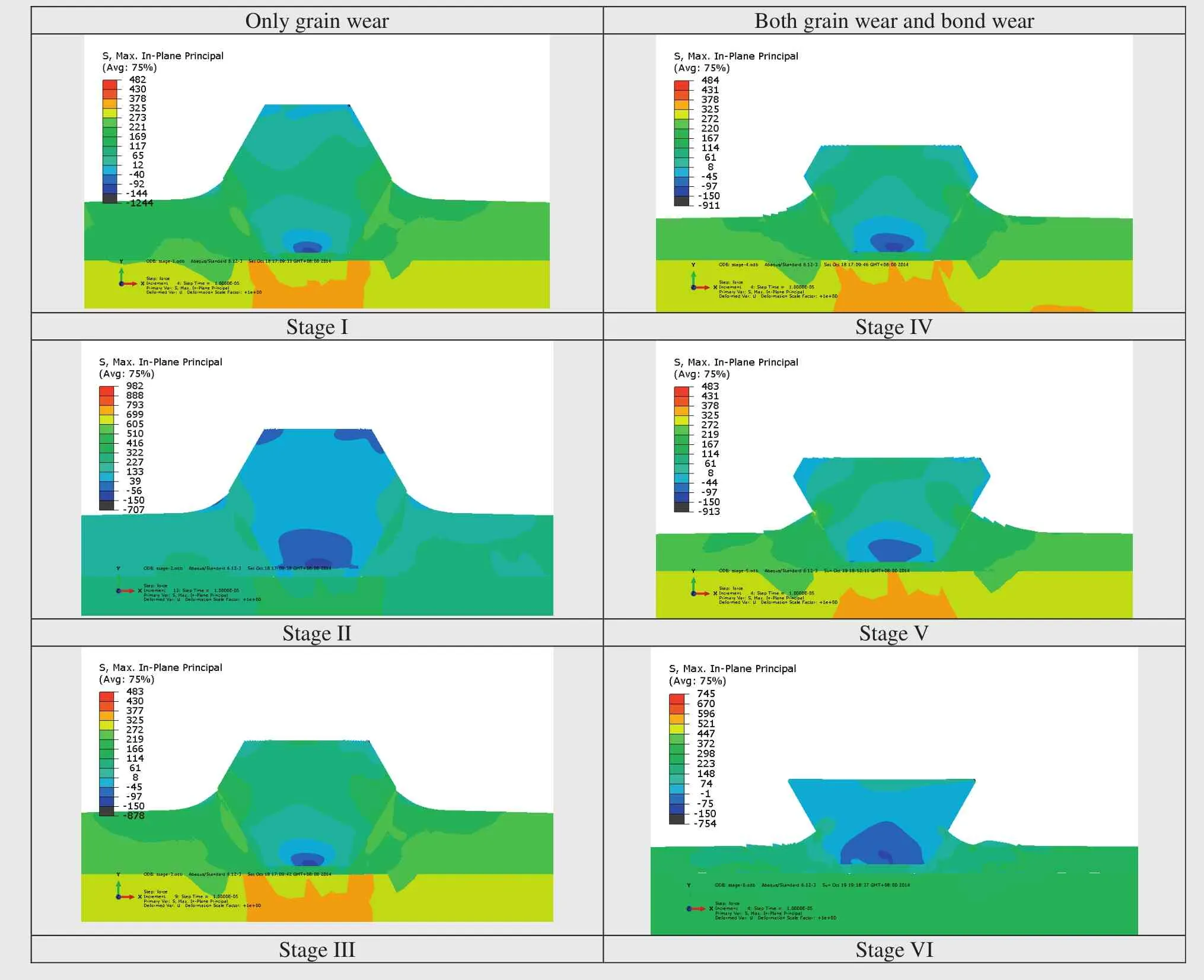
Table 2 Contour maps of resultant stresses in brazed CBN grains at different wear stages during grinding.118
5.4.Effects of wheel wear on grinding process and results
5.4.1.Effects of wheel wear on grinding forces
Depending on the grinding conditions,only a small number of abrasive grains on the grinding wheel surface come in contact with the workpiece surface.Among this small number of active grains,usually a small portion cut and form chips while the other grains only plow or rub against the workpiece surface.97,101For this reason,Aurich et al.64pointed out that the grinding forces were usually distributed over a small range of kinematic grains at the beginning of monolayer CBN wheel life.Afterwards,due to the fact that the wheel wear in rough grinding would likely cause an increase in the number of kinematic grains,and meanwhile a decrease in chip space volume,the grinding forces were distributed over a large quantity of abrasive grains at the end of wheel life.Generally,irregular engagementand wearconditionscaused an unsteady running-in of the grinding wheel and limited the possibility to predict process behavior.64
Conventional composite-type alumina wheels are commercially utilized for grinding low-carbon steel,in which severe wheel loading can take place due to the formation of long chips and adhesion tendency of the workpiece material with the grains.However,the true nature of grain wear in a composite wheel is affected by many factors and therefore hard to model.The truing and dressing conditions also affect the wear mechanisms,in particular directly after dressing.111In comparison,in monolayer wheels the factors on grain wear are reduced in number.
Bhaduri et al.125compared monolayer brazed CBN and composite white alumina wheels.The experiments were conducted on AISI 1020 steel under dry conditions,with liquid nitrogen,and neat oil as cooling lubricant.The CBN wheel was found to outperform the alumina wheels in terms of grinding forces and grain wear.The wear of the CBN wheel was remarkably low when neat oil was applied.In contrast,large-scale adhesion and breakage of grains in white alumina wheel were observed under a cryogenic environment.A lubricating agent like neat oil appeared to be more suitable and resulted in better grinding performance than cryogenic cooling when grinding low-carbon steel.125–129
5.4.2.Effects of wheel wear on grinding temperatures
Upadhyaya and Malkin112reported the thermal aspects of grinding with single-layer electroplated CBN wheels,which were not periodically restored by dressing or truing as in the common case.The effect of wheel wear and fluid flow on the grinding temperatures and energy partition was determined through the grinding operation of AISI 52100 steel and Inconel 713C nickel-based superalloys.Low energy partition into the workpiecematerials,suchas,3%–8%ofthetotalgrindingheat,can be obtained at temperatures below the fluid boiling limit.Such low energy partition indicated that the shallow porosity on the wheel surface provided sufficient fluid to cool the workpiece material at the grinding zone.Furthermore,the energy partitionresultswereanalyzedintermsofatopographicalanalysis of the wheel surface and a thermal model which accounted for the removal of heat at the grinding zone by conduction to the abrasive grains and to the grinding fluid.112Progressive wheel wear tended to increase the total wear flat area mainly by increasing the active grain density at constant flat areas per grain.This tended to lower the grinding heat into the workpiece materials by enhancing heat conduction to the abrasive grains and grinding wheels,to increase the grinding forces,and to generate smoother and more uniformly ground surfaces.
The electroplated CBN wheel with defined grain pattern from Fig.19 was used in dry grinding.The workpiece material was heat-treated steel AISI 4140H(42CrMo4V,DIN EN 10132-3)of(60±2)HRC.As a side effect of higher workpiece temperatures with high depth of cut,adhesion of workpiece material occurred on this prototype wheel(Fig.34).86Thus,the friction between grinding wheel and workpiece further increased and resulted in higher temperatures.However,the material adhesion did not damage the prototype and even after many grinding operations without active cleaning of the grinding wheel surface the material adhesion did not accumulate.Instead,a stationary self-cleaning process occurred.Furthermore,material adhesions completely disappeared after grinding operations with comparatively low depth of cut,such asap=1 mm or 2 mm.The wear in dry grinding was dominated by attrition wear of the grains and only a few grain breakouts occurred.86
Chen et al.130carried out dry grinding experiments of Ti–6Al–4V titanium alloy using monolayer brazed CBN wheels with a coating of polymer-based graphite lubricant.A great reduction of grindingtemperature,i.e.,42%–47%,was obtained with the coated wheel in comparison to the uncoated counterpart.
In summary,single-layer brazed or electroplated CBN wheels offer a solution for the high heat production in grinding.As well known,chip formation in grinding usually involves high specific energy compared to other machining processes(such as milling and turning)due to large negative rake angles of the cutting edges of grains.131Excessive friction between chip-grain and chip-bond interfaces occurs when the chips flow between grains and workpiece surface.Especially in dry grinding of metallic materials,this generates much heat,which has a harmful effect on workpiece surface integrity.In contrast to the conventional grinding wheels,the single-layer counterparts produce favorable chips during grinding metallic materials in ductile mode with fewer grinding forces and lower specific energy.At the same time,Pal et al.131found that large volume chips could not be accommodated in the small intergrain spaces of electroplated CBN wheels due to their dense grain distribution and low grain protrusion.However,even with a large chip load,the brazed CBN wheels worked effectively due to wider and more uniform spacing and larger protrusion of the grains.
5.4.3.Effects of wheel wear on ground surface quality
The wheel wear and change of active cutting edges always have a great influence on the ground surface quality.Some early investigations of the grinding process with electroplated CBN wheels were mainly concerned with characterization ofthe grinding performance,in termsofthe grinding power and surface roughness.21In subsequent studies,attention was directed to identifying the wheel wear mechanisms and the influence of workpiece materials and grinding fluid.132,133
For example,Shi and Malkin13carried out internal cylindrical grinding of hardened AISI 52100 steel(hardness HRC 62)with electroplated CBN wheels.They analyzed how the wear of CBN grains affected the wheel topography and ground surface roughness.Starting with a new wheel,the power was generally found to increase with continued grinding,which was accompanied by a corresponding decrease in surface roughness to a steady-state value.1The initial higher surface roughness came from exposed grain tips.7At the same time,dulling of CBN grains by attrition wear was high for a new wheel;the degree of grain dulling was restricted mainly by grain fracture and pullout.Grain fracture and pullout contributed only little to the progressive increase in active grain density,which caused a progressive decrease in surface roughness.Furthermore,an uneven grain protrusion distribution increased the resultant workpiece surface roughness.For this reason,the average value and distribution of the grain count as well as the protrusion height needs to be known to properly selecta wheeland dressing strategy fora particular application.71
6.Modeling and simulation of grinding process and mechanism with monolayer CBN wheels
Brinksmeier et al.134reviewed the advances on modeling and simulation of grinding processes,including physical process models(analytical and numerical models),empirical process models(regression analysis,artificial neural net models),as well as heuristic process models(rule based models).The models are mainly used to predict process parameters such as grinding force,grinding temperature,as well as surface topography and surface integrity.135–140Particularly,Liand Rong141,142established a grinding process model based on the time-dependent microscopic interactions,as displayed in Fig.35,which provided a quantitative description of the ‘inside story”within the grinding zone through separation and quantification of the six microscopic interaction modes,which included grain-workpiece interface(consisting of three modes,such as cutting,plowing and sliding),bond-workpiece interface,chip-workpiece interface,and chip-bond interface.143Further development of this model could include different grinding process kinematics,such as slot grinding,profile grinding,or more efficient computation algorithms.144
As for the grinding mechanism,Ding et al.145carried out a finite element analysis to investigate the effects of grinding speedsanduncutchipthicknessonchipformationduringsingle grain grinding of Inconel 718 nickel-based superalloy.Three factors,such as strain hardening,strain-rate hardening,and thermal-softening,were taken into accounts.Accordingly,a critical value of grinding speed was determined based on the variations of equivalent plastic strain,von Mises stress,and grinding forces.Similar experimental work was also conducted withsinglediamondor CBNgrains,146–150whichledtoadeeper understanding of the grinding mechanism of metallic materials.
Additionally,an understanding of the grinding heat could contribute to control effectively the thermal damage of the ground metallic materials.In the thermal simulation of grinding processes,a widely used approach is to substitute numerous cutting edges by a single moving distributed heat source of a specific geometrical shape referring to the theory of Jaeger.151This heat source can be moved across the workpiece according to the specific kinematics of the grinding process.Anotherapproach to determine theheatsource distribution based on a geometric-kinematic simulation for internal traverse grinding was presented by Schumann et al.62,who identified the ideal geometrical interaction of workpiece and tool.The specific material removal rate for each grain was calculated and accumulated with respect to the contact zone resulting in a three-dimensional(3D)thermal load distribution.This heat source can be used in finite element simulations to determine the thermal loads on the workpiece.62In comparison to the classical approach,the simulated temperature peaks happened within the contact zone because of locally concentrated grain engagements,which have been confirmed true in high-speed grinding experiments of 102Cr6 hardened steel(HRC 62–64)when using a monolayer electroplated CBN wheel.
7.Application of monolayer CBN wheels in grinding of metallic materials
7.1.Grinding of steel materials
Grinding of steel materials is complicated when the material adheres to the grains leading to wheel loading and subsequently high grinding temperatures,harmful residual stresses,severe tool wear,and bad surface quality.152–157Monolayer CBN wheels can be useful in this regard as they possess relatively high grain protrusion(compared to conventional composite wheels),which offers higher chip space and less chance of wheel loading.15
Marschalkowski et al.158presented a study on internal peel grinding,using combined roughing and finishing in combination with the excellent cutting performance of electroplated CBN wheels,to achieve the highest removal rates with high surface finish.Vashista et al.159investigated the role of process parameters on grindability of AISI 1060 medium carbon steel with particular emphasis on surface integrity.Grinding with miniature monolayer electroplated CBN wheels provided compressive residual stresses throughout the experimental domain unlike conventional grinding,which can be attributed to a better temperature control capacity as the electroplated CBN wheel took away substantial part of grinding heat through its better thermal conductivity.Meanwhile,an increase in depth of cut resulted in more grain elongation in the steel and higher surface microhardness due to higher mechanical loads during chip formation.Xu et al.160developed a precise electroplated CBN gear-honing cutter for hardened gears with narrow tooth faces.The quality of the tooth face was enhanced,noise decreased effectively and radialerror improved with this innovative cutting tool.Similar work on gear honing tools was also carried out by Lv et al.161.
Chattopadhyay et al.12,30,162reported the application of brazed CBN wheels in grinding steel materials,such as unhardened 100Cr6 steel,IS 103Cr1 bearing steel(62 HRC),and high speed steel(65 HRC).Improved performance of brazed wheels over electroplated wheels was evident for high material removal rates and large stock removal.
7.2.Grinding of titanium alloys
Titanium alloys are broadly applied as the most common structural metallic material in the aerospace and defense industry and other fields owing to their favorable mechanical properties and resistance to surface corrosion,even under hightemperature conditions.163Unfortunately,the unique physical and chemical properties contribute also to difficulties in cutting and grinding titanium alloys.164
Shi and Attia165,166carried out experimental studies on grinding of titanium alloy with electroplated CBN wheels.They demonstrated that enhanced removal rates are achievable by wheel cleaning with fluids at high pressures.The specific material removal rates of 8 mm3/mm·s in shallow cut mode and 3 mm3/mm·s at a depth of cut as high as 3 mm in creepfeed mode were achieved without thermal damage and smearing of ground surfaces.166
Teicher et al.167compared the grindability of Ti–6Al–4V alloy with brazed CBN and diamond grinding wheels under different environments.Cryogenic cooling did not improve the surface roughness for both CBN and diamond,but the application of oil or alkaline cooling lubricants gave the best results.Likewise,Yang et al.168applied brazed CBN profile wheels to machine an aero-engine blade rabbet made of Ti–6Al–4V.Good dimensional accuracy and favorable surface integrity was achieved.
7.3.Grinding of nickel-based superalloys
With broader application of nickel-based superalloys in the aerospace industry,milling and turning operations can hardly meet the quality requirements due to short tool life,cutting vibrations,and high machining forces.169–175As an alternative to defined cutting operations,Li et al.10investigated highspeed grinding of an integrated impeller made of GH4169 nickel-based superalloy(which is similar to Inconel718)with an electroplated CBN wheel.Compared with the milling process,the profile error of blades was reduced by about 50%and surface quality was improved.Zhao et al.176carried out grinding experiments of DZ125 directional solidified nickelbased superalloy with an electroplated CBN profile wheel.High shape accuracy and good surface integrity was obtained even at a high specific material removal rate of 50 mm3/(mm·s).
Tian et al.19developed an electroplated CBN wheel with miniature concave and convex asperities on its circumferential surface to manufacture thin-walled and honeycomb-structured components made up of a nickel-based superalloy(Hastelloy X),as displayed in Fig.36.One of the principal challenges while manufacturing honeycombs was their extreme sensitivity towards cell distortion and burr formation in grinding.177Similar to the advantages of intermittent grinding with slotted or segmented wheels,grinding power and force were reduced due to the miniature concave and convex asperities on the wheel circumferential working surface.19Furthermore,burr size was reduced owing to low grinding forces.
Creep-feed grinding has been expected to improve material removal rates and surface quality of components with complex profiles.Ding et al.20studied experimentally the effects of process parameters(in particular wheel speed,workpiece speed,and depth of cut)on grindability and surface integrity of K424 cast nickel-based superalloys during creep-feed grinding with brazed CBN wheels.Low grinding temperatures of about 100°C were obtained though the specific grinding energy was high with values up to 200–300 J/mm3for nickel-based superalloys.Compressive residual stresses were produced in the ground surface without thermal damage or cracks.20Furthermore,Li et al.45and Ding et al.46also evaluated the high-speed grinding performance of brazed CBN wheels for Inconel718 alloy and obtained satisfactory surface quality.
8.Concluding remarks and outlook
This article comprehensively reviewed manufacturing and performance of monolayer electroplated and brazed CBN wheels.Important aspects regarding the fabrication mechanism,grain distribution,dressing techniques,tool wear,and application technology were highlighted.Although great progress has been made in recent years,there are still significant challenges for monolayer CBN wheels as follows:
(1)High-quality joining between CBN grains and wheel hub includes both,a strong bonding mechanism and low damage to the grains.However,the current electroplating and brazing techniques do not fully provide these integrated advantages.For this reason,new joining technologies between CBN grains and wheel substrates need to be developed.
(2)Grain distribution and working surface patterns have a great influence on the grinding performance of monolayer CBN wheels.However,current approaches have not achieved the full potential.Grain distribution and working surface patterns need to be optimized further,for example with the promising phyllotaxis theory gained from biology.
(3)The current investigation on grinding processes is based on the average values of uncut chip thickness,which limits greatly the ability to accurately predict and control the grinding results.It is necessary to characterize the actual surface topography of monolayer CBN wheels and determine the actual distribution of uncut chip thickness in grinding.
(4)Traditional monocrystalline CBN grains used for monolayer CBN wheels do rarely self-sharpen but become dull due to attrition in grinding,which decreases the grinding performance.It is necessary to develop monolayer wheels with grain self-sharpening ability in order to make full use of the grinding potential of CBN superabrasive grains.
(5)The current grinding model and simulation work for monolayer wheel is still at the theoretical stage,and its application potential is rather limited.In order to control the grinding quality and increase removal rates of materials,further development of grinding process models is necessary.
Acknowledgements
The authors gratefully acknowledge the financial support for this work by the National Natural Science Foundation of China(Nos.51235004 and 51375235),the Fundamental Research Funds for the Central Universities (Nos.NE2014103 and NZ2016107).
1.Konig W,Schleich H,Yegenoglu K.High-performance grinding with electroplated CBN wheels.Ind Diam Rev1984;44(6):320–3.
2.Upadhyaya RP,Fiecoat JH.Factors affecting grinding performance with electroplated CBN wheels.CIRP Ann–Manuf Technol2007;56(1):339–42.
3.Ghosh A,Chattopadhyay AK.On grit-failure of an indigenously developed single layer brazed CBN wheel.Ind Diam Rev2007;67(1):59–64.
4.Linke B.Life cycle and sustainability of abrasive tools.Springer International Publishing Switzerland;2016.p.64–79.
5.Yang XH,Bai JG,Jing WJ,Wang B,Yang JF.Strengthening of low-temperature sintered vitrified bond cBN grinding wheels by pre-oxidation of cBN abrasives.Ceram Int2016;42(7):9283–6.
6.Ghosh A,Chattopadhyay AK.Experimental investigation on performance of touch-dressed single-layer brazed cBN wheels.Int J Mach Tools Manuf2007;47(7–8):1206–13.
7.Jackson MJ,Davis CJ,Hitchiner MP,Mills B.High-speed grinding with CBN grinding wheels–applications and future technology.J Mater Process Technol2001;110(1):78–88.
8.Konig W,Ferlemann F.A new dimension for high-speed grinding.Ind Diam Rev1991;91(5):237–41.
9.Pal B.Development and performance of brazed type monolayer cBN wheel[dissertation].Kharagpur:Indian Institute of Technology;1999.
10.Li X,Meng FJ,Cui W,Ma S.The CNC grinding of integrated impeller with electroplated CBN wheel.Int J Adv Manuf Technol2015;79(5):1353–61.
11.Zhao QL,Guo B.Ultra-precision grinding of optical glasses using mono-layer nickel electroplated coarse-grained diamond wheels.Part 1:ELID assisted precision conditioning of grinding wheels.Precis Eng2015;39:56–66.
12.Pal B,Chattopadhyay AK,Chattopadhyay AB.Development and performance evaluation of monolayer brazed cBN grinding wheel on bearing steel.Int J Adv Manuf Technol2010;48(9):935–44.
13.Shi Z,Malkin S.An investigation of grinding with electroplated CBN wheels.CIRP Ann–Manuf Technol2003;52(1):267–70.
14.Klocke F,Brinksmeier E,Evans C.High-speed grindingfundamentals and state of the art in Europe,Japan,and the USA.CIRP Ann–Manuf Technol1997;46(2):715–24.
15.Bhaduri D,Chattopadhyay AK.Effect of pulsed DC CFUBM sputtered TiN coating on performance of nickel electroplated monolayer cBN wheel in grinding steel.Surf Coat Technol2010;204(23):3818–32.
16.Malkin S.Current trends in CBN grinding technology.CIRP Ann–Manuf Technol1985;34(2):557–63.
17.Puerto P,Kirsch B,Madariaga J,Fernandez R,Aurich JC,Gallego I.A comparison of techniques to measure the wear flat area of conventional and superabrasive grinding wheels.J Tribol–Trans ASME2015;137(2):Article No.024503.
18.Ding WF,Xu JH,Shen M,Fu YC,Xiao B,Su HH,Xu HJ.Development and performance of monolayer brazed CBN grinding tools.Int J Adv Manuf Technol2007;34(5):491–5.
19.Tian YB,Zhong ZW,Rawat R.Comparative study on grinding of thin-walled and honeycomb-structured components with two CBN wheels.Int J Adv Manuf Technol2015;81(5):1097–108.
20.Ding WF,Xu JH,Chen ZZ,Su HH,Fu YC.Grindability and surface integrity of cast nickel-based superalloy in creep feed grinding with brazed CBN abrasive wheels.Chin J Aeronaut2010;23(4):501–10.
21.Shi Z,Malkin S.Wear of electroplated CBN grinding wheels.J Manuf Sci Eng–Trans ASME2006;128(1):110–8.
22.Bhaduri D,Kumar R,Jain AK,Chattopadhyay AK.On tribological behaviour and application of TiN and MoS2-Ti composites coating for enhancing performance of monolayer cBN grinding wheel.Wear2010;268(9–10):1053–65.
23.Liu YP,Mu LP,Liu Z,Xu P.The construction design of adjustable gear-type electroplating-CBN-honing tool and study on its new electroplating technique.4th International conference on progress of cutting and grinding;1998 Oct.5-9;Urumqi,China.1998.p.392–6.
24.Aurich JC,Carrella M,Walk M.Micro grinding with ultra small micro pencil grinding tools using an integrated machine tool.CIRP Ann–Manuf Technol2015;64(1):325–8.
25.Walk M,Aurich JC.Integrated desktop machine tool for manufacturing and application of ultra-small micro pencil grinding tools.Proc CIRP2014;14:333–8.
26.Liu Z,Niu ZG,Liu YP,Xu P.The design of assembly-type CBN honing-worm and its electroplating technique.4th International conference on progress of cutting and grinding;1998 Oct.5–9;Urumqi,China.1998.p.397–402.
27.Bhaduri D,Chattopadhyay AK.Influence of grinding parameters and substrate bias voltage in dry surface grinding with TiN-coated single layer galvanic cBN wheel.Mater Manuf Process2011;26(8):982–90.
28.Ghosh A,Chattopadhyay AK.Performance enhancement of single-layer miniature cBN wheels using CFUBMS-deposited TiN coating.Int J Mach Tools Manuf2007;47(12–13):1799–806.
29.Bhaduri D,Chattopadhyay AK.Study on the role of PVD TiN coating in improving the performance of electroplated monolayer superabrasive wheel.Surf Coat Technol2010;205(2):658–67.
30.Chattopadhyay AK,Chollet L,Hintermann HE.Improved monolayer cBN wheel for load free grinding.Int J Mach Tools Manuf1992;32(4):571–81.
31.Ghosh A,Chattopadhyay AK.Influence of process parameters on transverse profile of work surfaces ground by a single layer brazed cBN wheel.Int J Abras Technol2009;2(1):97–111.
32.Chattopadhyay AK,Chollet L,Hintermann HE.On performance of chemically bonded single-layer cBN grinding wheel.CIRP Ann–Manuf Technol1990;39(1):309–12.
33.Hintermann HE,Chattopadhyay AK.New generation superabrasive tool with monolayer configuration.Diam Relat Mater1992;1(12):1131–43.
34.Sieniawski J,Nadolny K.The effect upon grinding fluid demand and workpiece quality when an innovative zonal centrifugal provision method is implemented in the surface grinding of steel CrV12.J Clean Prod2016;113:960–72.
35.Chattopadhyay AK,Hintermann HE.On brazing of cubic boron nitride abrasive crystals to steel substrate with alloys containing Cr or Ti.J Mater Sci1993;28(21):5887–93.
36.Naidich VV,Adamovskyi AA.Brazing of cubic boron nitride base superhard materials.3rd International brazing and soldering conference;2006 Apr.24–26;San Antonio,Texas,USA.2006.p.133–5.
37.Ding WF,Xu JH,Chen ZZ,Miao Q,Yang CY.Interface characteristics and fracture behavior of brazed polycrystalline CBN grainsusing Cu–Sn–Tialloy.MaterSciEngA2013;559:629–34.
38.Pobol IL,Shipko AA,Nesteruk IG.Investigation of contact phenomena at cubic boron nitride-filler metal interface during electron beam brazing.Diam Relat Mater1997;6(8):1067–70.
39.Wang Y,Qiu XM,Lu GL,Ren LQ.The weldability and microstructure of c-BN brazed with CuNiSnTi filler metal.Rate Metal Mater Eng2007;36(S3):343–6.
40.Ding WF,Miao Q,Xu JH,Chen ZZ,Yang CY,Fu YC.Preparation mechanism and grinding performance of single-layer self-lubrication brazed CBN abrasive wheels.Int J Adv Manuf Technol2013;68(1):249–55.
41.Ding WF,Xu JH,Chen ZZ,Cheng Z,Fu YC.A study on effects of TiB2contents on reactive products and compressive strength of brazed CBN grains.Surf Interf Anal2009;41(3):238–43.
42.Ding WF,Xu JH,Chen ZZ,Su HH,Fu YC.Brazed joints of CBN grains and AISI 1045 steel with AgCuTi-TiC mixed powder as filler materials.Int J Min Metall Mater2011;18(6):717–24.
43.Felba J,Friedel KP,Krull P,Pobol IL,Wohlfahrt H.Electron beam activated brazing of cubic boron nitride to tungsten carbide cutting tools.Vacuum2001;62(2–3):171–80.
44.Ding WF,Xu JH,Shen M,Su HH,Fu YC,Xiao B.Joining of CBN abrasive grains to medium carbon steel with Ag-Cu/Ti powder mixture as active brazing alloy.Mater Sci Eng A2006;430:301–6.
45.Li QL,Xu JH,Su HH,Lei WN.Fabrication and performance of monolayer brazed CBN wheel for high-speed grinding of superalloy.Int J Adv Manuf Technol2015;80:1173–80.
46.Ding WF,Miao Q,Xu JH,Ma CY,Zhao B,Yang CY.Joining interface and grain fracture of single-layer brazed grinding wheels with binderlessCBN grains.IntJAdvManufTechnol2013;68:1261–6.
47.Miab RJ,Hadian AM.Effect of brazing time on microstructure and mechanical properties of cubic boron nitride/steel joints.Ceram Int2014;40(6):8519–24.
48.Elsener HR,Klotz UE,Khalid FA,Piazza D,Kiser M.The role of binder content on microstructure and properties of a Cu-base active brazing filler metal for diamond and cBN.Adv Eng Mater2005;7(5):375–80.
49.Miao Q,Ding WF,Zhu YJ,Chen ZZ,Xu JH,Yang CY.Joining interface and compressive strength of brazed cubic boron nitride grains with Ag-Cu-Ti/TiX composite fillers.Ceram Int2016;42(12):13723–37.
50.Ma XY,Li CR,Zhang WJ.Study on the phase diagram of the Ti-B-N system and the interfacial reaction of the Ti/BN joints.Mater Sci Eng A2005;392:394–402.
51.Faran E,Gotman I,Gutmanas EY.Coating of BN via solid state reaction with Ti-powder.Mater Lett2000;43:192–6.
52.Faran E,Gotman I,Gutmanas EY.Experimental study of the reaction zone at boron nitride ceramic-Ti metal interface.Mater Sci Eng A2000;288:66–74.
53.Ding WF,Xu JH,Shen M,Fu YC,Xiao B.Thermodynamic and kinetic analysis of interfacial reaction between CBN and titanium activated Ag-Cu alloy.Mater Sci Technol2006;22(1):105–9.
54.Wang YH,Wang MZ,Wen XY,Zang JB.Reaction between Ticoated cBN and SiO2-Na2O-B2O3glass bond.J Inorg Mater1995;10:351–5.
55.Gotman I,Travitzky NA,Gutmanas EY.Dense in situ TiB2/TiN and TiB2/TiC ceramic matrix composites:reactive synthesis and properties.Mater Sci Eng A1998;244:127–37.
56.Kitiwan M,Ito A,Goto T.Spark plasma sintering of TiN-TiB2-hBN composites and their properties.Ceram Int2015;41(3):4498–503.
57.Lin TS,Yang MX,He P,Huang C,Pan F,Huang YD.Effect of in situ synthesized TiB whisker on microstructure and mechanical properties of carbon-carbon composite and TiBw/Ti-6Al-4V composite joint.Mater Des2011;32(8–9):4553–8.
58.Mirkarimi PB,McCarty KF,Medlin DL.Review of advances in cubic boron nitride film synthesis.Mater Sci Eng R1997;21(2):47–100.
59.Russias J,Cardinal S,Fontaine J,Fantozzi G,Esnouf C,Bienvenu K.Bulk titanium nitride material obtained from SHS starting powder:densification,mechanical characterization and tribological approach.Int J Refract Met Hard Mater2005;23(4–6):344–9.
60.Vallauri D,Adrian ICA,Charysantou A.TiC-TiB2composites:a review of phase relationships,processing and properties.J Euro Ceram Soc2008;28(8):1697–713.
61.Wang T,Zou CL,Chen ZN,Li MY,Wang W,Li RG,et al.In situ synthesis of TiB2particulate reinforced copper matrix composite with a rotating magnetic field.MaterDes2015;65:280–8.
62.Schumann S,Siebrecht T,Kersting P,Biermann D,Holtermann A,Menzel A.Determination of the thermal load distribution in internal traverse grinding using a geometric-kinematic simulation.Proc CIRP2015;31:322–7.
63.Linke BS.A review on properties of abrasive grits and grit selection.Int J Abras Technol2015;7(1):46–58.
64.Aurich JC,Braun O,Warnecke G.Development of a superabrasive grinding wheel with defined grain structure using kinematic simulation.CIRP Ann–Manuf Technol2003;52(1):275–80.
65.Kirsch B,Aurich JC.Influence of the macro-topography of grinding wheels on the cooling efficiency and the surface integrity.Proc CIRP2014;13:8–12.
66.Opoz T,Chen X.Experimental investigation of material removal mechanism in single grit grinding.Int J Mach Tools Manuf2012;63:32–40.
67.Transchel R,Heini F,Stimimann J,Kuster F,Leinenbach C,Wegener K.Influence of the clearance angle on the cutting efficiency of blunt,octahedral-shaped diamonds in an active filler alloy.Int J Mach Tools Manuf2013;75:9–15.
68.Bailey MW,Juchem HO.The advantages of cBN grinding:low cutting forces and improved workpiece integrity.Ind Diam Rev1998;3:83–9.
69.Li HN,Yu TB,Zhu LD,Wang WS.Modeling and simulation of grinding wheel by discrete element method and experimental validation.Int J Adv Manuf Technol2015;81(9):1921–38.
70.Ghosh A,Chattopadhyay AK.On cumulative depth of touchdressing of single layer brazed cBN wheels with regular grit distribution pattern.Mach Sci Technol2007;11(2):259–70.
71.Li XK,Wolf S,Zhi G,Rong YM.The modelling and experimental verification of the grinding wheel topographical properties based on the ‘through-the-process’method.Int J Adv Manuf Technol2014;70(1):649–59.
72.Denkena B,Grove T,Gottsching T.Grinding with patterned grinding wheels.CIRP J Manuf Sci Technol2015;8:12–21.
73.Rabiey M,Tawakoli T,Wegener K.The effect of special structured electroplated CBN wheel in dry grinding of 100Cr6.Adv Mater Res2009;76–78:119–24.
74.Tawakoli T,Westkaemper W,Rabiey M.Dry grinding by special conditioning.Int J Adv Manuf Technol2007;33(3):419–24.
75.Silva EJ,Oliveira JFG,Salles BB,Cardoso RS,Reis VRA.Strategies for production of parts textured by grinding using patterned wheels.CIRP Ann–Manuf Technol2013;62(1):355–8.76.Tawakoli T,Lee DH,Daneshi A.Green grinding with innovative wheel topography.Int J Precis Eng Manuf2013;14(7):1209–12.
77.Kim JD,Kang YH,Jin DX,Lee YS.Development of discontinuous grinding wheel with multi-porous grooves.Int J Mach Tools Manuf1997;37(11):1611–24.
78.Lee KW,Wong PK,Zhang JH.Study on the grinding of advanced ceramics with slotted diamond wheels.J Mater Process Technol2000;100(1–3):230–5.
79.Nakayama K,Takaji J,Abe T.Grinding wheel with helical grooves-an attempt to improve the grinding performance.CIRP Ann–Manuf Technol1977;25(1):133–8.
80.Mohamed AMO,Bauer R,Warkentin A.Application of shallow circumferential grooved wheels to creep-feed grinding.J Mater Process Technol2013;213(5):700–6.
81.Oliveira JFG,Bottene AC,Franca TV.A novel dressing technique for texturing of ground surfaces.CIRP Ann–Manuf Technol2010;59(1):361–4.
82.Yuan HP,Gao H,Bao YJ,Wu Y.Grinding of carbon/epoxy composites using electroplated CBN wheel with controlled abrasive clusters.Key Eng Mater2009;389–390:24–9.
83.Walter C,Komischke T,Kuster F,Wegener K.Laser-structured grinding tools–generation of prototype patterns and performance evaluation.J Mater Process Technol2014;214(4):951–61.
84.Walter C,Komischeke T,Weingartner E,Wegener K.Structuring of CBN grinding tools by ultrashort pulse laser ablation.Proc CIRP2014;14:31–6.
85.Aslan D,Budak E.Surface roughness and thermo-mechanical force modeling for grinding operations with regular and circumferentially grooved wheels.JMaterProcessTechnol2015;223:75–90.
86.Aurich JC,Herzenstiel P,Sudermann H,Magg T.Highperformance dry grinding using a grinding wheel with a defined grain pattern.CIRP Ann–Manuf Technol2008;57(1):357–62.
87.Warnecke G,Zitt U.Kinematic simulation for analyzing and prediction high-performance grinding processes.CIRP Ann–Manuf Technol1998;47(1):265–70.
88.Herzenstiel P,Aurich JC.CBN-grinding wheel with a defined grain pattern-extensive numerical and experimental studies.Mach Sci Technol2010;14(3):301–22.
89.Aurich JC,Kirsch B.Kinematic simulation of high-performance grinding for analysis of chip parameters of single grains.CIRP J Manuf Sci Technol2012;5(3):164–74.
90.Denkena B,Grove T,Gottsching T,Silva EJ,Coelho RT,FilletiR.Enhanced grinding performanceby meansof patterned grinding wheels.Int J Adv Manuf Technol2015;77(9):1935–41.
91.Denkena B,Grove T,Lucas H.Influence of grinding with Toric CBN grinding tools on surface and subsurface of 1.3344 PM steel.J Mater Process Technol2016;229:541–8.
92.Burkhard G,Rehsteiner F.High efficiency abrasive tool for honing.CIRP Ann–Manuf Technol2002;51(1):271–4.
93.Wardlaw CW.Phyllotaxis and organogenesis in ferns.Nature1949;164:167–9.
94.Liu ZZ,Wang J,Lu YS,Ma F,Xiang L,Zhang S.Fabrication of the electroplated CBN wheel for cylindrical grinding with abrasive phyllotactic pattern.Adv Mater Res2015;1077:44–9.
95.Yu HY,Wang J,Lu YS.Modeling and analysis of dynamic cutting points density of the grinding wheel with an abrasive phyllotactic pattern.IntJAdvManufTechnol2016;86(5):1933–43.
96.Yu HY,Wang J,Lu YS.Simulation of grinding surface roughness using the grinding wheel with an abrasive phyllotactic pattern.Int J Adv Manuf Technol2016;84(5):861–71.
97.Hecker RL,Ramoneda IM,Liang SY.Analysis of wheel topography and grit force for grinding process modeling.J Manuf Process2003;5(1):13–23.
98.Inasaki I.Grinding process simulation based on the wheel topography measurement.CIRP Ann–Manuf Technol1996;45(1):347–50.
99.Koshy P,Iwasaki A,Elbestawi MA.Surface generation with engineered diamond grinding wheels:insights from simulation.CIRP Ann–Manuf Technol2003;52(1):271–4.
100.Ghosh A.Coating and microdressing of monolayer cBN abrasive wheel for improvement in productivity and surface quality[dissertation].Kharagpur:Indian Institute of Technology;2003.
101.Nguyen TA,Butler DL.Simulation of precision grinding processes,Part 1:Generation of the grinding wheel surface.Int J Mach Tools Manuf2005;45(11):1321–8.
102.Ding WF,Xu JH,Chen ZZ,Su HH,Fu YC.Wear behavior and mechanism of single-layer brazed CBN abrasive wheels during creep-feed grinding cast nickel-based superalloy.Int J Adv Manuf Technol2010;51(5):541–50.
103.Tawakoli T,Maftoon H,Tavakkoli JS.HEDG with touchdressed cBN wheel.Ind Diam Rev1991;391:131–5.
104.Warhanek M,Walter C,Huber S,Hanni F,Wegener K.Cutting characteristics of electroplated diamond tools with laser-generated positive clearance.CIRP Ann–Manuf Technol2015;64(1):317–20.
105.Ju Y,Farris TN,Chandrasekar S.Theoretical analysis of heat partition and temperature in grinding.J Tribol–Trans ASME1998;120(4):789–94.
106.Zhang YB,Li CH,Jia DZ,Zhang DK,Zhang XW.Experimental evaluation of MoS2nanoparticles in jet MQL grinding with different types of vegetable oil as base oil.J Clean Prod2015;87:930–40.
107.Zhang ZY,Wang B,Kang RK,Zhang B,Guo DM.Changes in surface layer of silicon wafers from diamond scratching.CIRP Ann–Manuf Technol2015;64:349–52.
108.Zhang ZY,Zhang XZ,Xu CG,Guo DM.Characterization of nanoscale chips and a novel model for face nanogrinding on softbrittle HgCdTe films.Tribol Lett2013;49:203–15.
109.Linke BS.Review on grinding tool wear in terms of sustainability.Proceedings of the ASME 2014 international manufacturing science and engineering conference;2014,Jun.9–13;Detroit,Michigan,USA.2014.p.1–9.
110.Yu TY,Bastawros AF,Chandra A.Experimental characterization of electroplated CBN grinding wheel wear:topology evolution and interfacial toughness.Proceedings of the ASME 2014 international manufacturing science and engineering conference;2014,Jun.9–13;Detroit,Michigan,USA.2014.p.1–8.
111.Linke BS.Review on grinding tool wear with regard to sustainability.J Manuf Sci Eng–Trans ASME2015;137:Article No.060801.
112.Upadhyaya RP,Malkin S.Thermal aspects of grinding with electroplated CBN wheels.J Manuf Sci Eng–Trans ASME2004;126:107–14.
113.Li XK,Wolf S,Zhu TX,Zhi G,Rong YM.Modelling and analysis of the bonding mechanism of CBN grains for electroplated superabrasive tools–Part 1:Introduction and application of a novel approach for determining the bonding force and the failure modes.Int J Adv Manuf Technol2015;76(9):2051–8.
114.Shao YM,Fergani O,Ding ZS,Li BZ,Liang SY.Experimental investigation of residual stress in minimum quantity lubrication grinding of AISI 1018 steel.J Manuf Sci Eng–Trans ASME2016;138.Article No.011009.
115.Li XK,Wolf S,Zhu TX,Zhi G,Rong YM.Modelling and analysis of the bonding mechanism of CBN grains for electroplated superabrasive tools–Part 2:Finite element modeling and experimental veri fication.Int J Adv Manuf Technol2015;77(1):43–9.
116.Zhou Y,Funkenbusch PD,Quesnel DJ.Stress distribution at the abrasive-matrix interface during tool wear in bound abrasive grinding – a finite element analysis.Wear1997;209:247–54.
117.Yu TY,Bastawros AF,Chandra A.Modeling wear process of electroplated CBN grinding wheel.Proceedings of the ASME 2015 international manufacturing science and engineering conference;2015,Jun.8–12;Charlotte,North Carolina,USA.2015.p.1–7.
118.Ding WF,Zhu YJ,Xu JH,Fu YC.Finite element investigation on the evolution of wear and stresses in brazed CBN grits during grinding.Int J Adv Manuf Technol2015;81(5):985–93.
119.Ding WF,Zhu YJ,Zhang LC,Xu JH,Fu YC,Liu WD,Yang CY.Stress characteristics and fracture wear of brazed CBN grains in monolayer grinding wheels.Wear2015;332–333:800–9.
120.Zhu YJ,Ding WF,Xu JH,Yang CY.An investigation of residual stresses in brazed cubic boron nitride abrasive grains by finite element modelling and Raman spectroscopy.Mater Des2015;87:342–51.
121.Zhang Z,Linke B,Klocke F,Xu J,Schindler F.Measurement of the pattern on grinding wheels.Diam Tool J2010;4(10):24–7.
122.Fujimoto M,Ichida Y.Micro fracture behavior of cutting edges in grinding using single crystal cBN grains.Diam Relat Mater2008;17(7–10):1759–63.
123.Miao Q,Ding WF,Xu JH,Yang CY,Fu YC.Fractal analysis of wear topography of brazed polycrystalline cBN abrasive grains during grinding nickel superalloy.Int J Adv Manuf Technol2013;68(9):2229–36.
124.Ding WF,Miao Q,Zhu YJ,Xu JH,Fu YC.Comparative investigation on wear behavior and self-sharpening phenomenon of polycrystalline cubic boron nitride and monocrystalline cubic boron nitride grains in high speed grinding.Proc Inst Mech Eng,Part B:J Eng Manuf2016;230(4):710–21.
125.Bhaduri D,Kumar R,Chattopadhyay AK.On the grindability of low-carbon steel under dry,cryogenic and neat oil environments with monolayer brazed cBN and alumina wheels.Int J Adv Manuf Technol2011;57(9):927–43.
126.Zhang DK,Li CH,Zhang YB,Jia DZ,Zhang XW.Experimental research on the energy ratio coef ficient and speci fic grinding energy in nanoparticle jet MQL grinding.Int J Adv Manuf Technol2015;78(5):1275–88.
127.Mao C,Zhang J,Huang Y,Zou HF,Huang XM,Zhou ZX.Investigation on the effect of nano fluid parameters on MQL grinding.Mater Manuf Process2013;28(4):436–42.
128.Mao C,Zou HF,Zhou X,Huang Y,Gan HY,Zhou ZX.Analysis of suspension stability for nano fluid applied in minimum quantity lubricant grinding.Int J Adv Manuf Technol2014;71(9):2073–81.
129.Lei XL,Shen B,Chen SL,Wang L,Sun DH.Tribological behavior between micro-and nano-crystalline diamond films under dry sliding and water lubrication.TribolInt2014;69:118–27.
130.Chen Y,Ding LY,Fu YC,Su HH,Wu J,Xu JH,et al.Dry grinding of titanium alloy using brazed monolayer cBN wheels coated with graphite lubricant.Trans Nanjing Univ Aeronaut Astronaut2014;31(1):104–10.
131.Pal B,Chattopadhyay AK,Chattopadhyay AB.Effect of chip morphology during grinding bearing steel using single layer brazed and galvanic bonded cubic boron nitride(cBN)wheel.Mater Manuf Process2011;26(8):991–6.
132.Ramanan NV,Foster MR.Wear mechanism of an electroplated CBN grinding wheel during grinding of a nickel base alloy with aqueous-based coolant.Proceedings of 2nd international machining and grinding conference;1997,Sep.8–11;Dearborn,Michigan,USA.1997.p.25–38.
133.Kumar KV.Technical advancements in CBN grinding products and applications.Proceedings of 2nd international machining and grinding conference;1997,Sep.8–11;Dearborn,Michigan,USA.1997.p.93–104.
134.Brinksmeier E,Aurich JC,Govekar E,Heinzel C,Hoffmeister F,Klocke F,et al.Advances in modeling and simulation of grindingprocesses.CIRPAnn–ManufTechnol2006;55(2):667–96.
135.Pearce TRA,Fricker DC,Speight A.The effect on workpiece roundness of the run-out of CBN electroplated grinding wheels.Key Eng Mater2007;329:483–8.
136.Wang S,Li CH,Zhang DK,Jia DZ,Zhang YB.Modeling the operation of a common grinding wheel with nanoparticle jet flow minimal quantity lubrication.Int J Adv Manuf Technol2014;74(5):835–50.
137.Shen B,Song B,Cheng L,Lei XL,Sun FH.Optimization on the HFCVD setup for the mass-production of diamond-coated micro-tools based on the FVM temperature simulation.Surf Coat Technol2014;253:123–31.
138.Tonshoff HK,Friemuth T,Becker JC.Process monitoring in grinding.CIRP Ann–Manuf Technol2002;51(2):551–71.
139.Shah SM,Nelias D,Zainulabdein M,Coret M.Numerical simulation of grinding induced phase transformation and residualstressesin AISI-52100 steel.FiniteElemAnalDes2012;61:1–11.
140.Wegener K,Hoffmeister HW,Karpuschewski B,Kuster F,Hahmann WC,Rabiey M.Conditioning and monitoring of grinding wheels.CIRP Ann–Manuf Technol2011;60(1):757–77.141.Li XK,Rong YM.Framework of grinding process modeling and simulation based on microscopic interaction analysis.Robot Comput-Integr Manuf2011;27(2):471–8.
142.Zhi G,Li XK,Bi WY,Tang JJ,Rong YM.The measurement and analysis of micro bonding force for electroplated CBN grinding wheels based on response surface methodology.Eng Fail Anal2015;57:377–88.
143.Subramanian S,Ramanath,Tricadrd M.Mechanism of material removal in the precision grinding of ceramics.J Manuf Sci Eng–Trans ASME1997;119:509–19.
144.Aurich JC,Kirsch B.Improved coolant supply through slotted grinding wheel.CIRP Ann–Manuf Technol2013;62(1):363–6.
145.Dai JB,Ding WF,Zhang LC,Xu JH,Su HH.Understanding the effects of grinding speed and undeformed chip thickness on the chip formation in high-speed grinding.Int J Adv Manuf Technol2015;81(5):995–1005.
146.Aurich JC,Steffes M.Single-grain scratch tests to determine elastic and plastic material behavior in grinding.Adv Mater Res2011;325:48–53.
147.Feng BF,Cai GQ,Sun XL.Groove,chip and force formation in single-grain high-speed grinding.Key Eng Mater2006;304–305:196–200.
148.Tian L,Fu YC,Xu JH,Li HY,Ding WF.The in fluence of speed on material removal mechanism in high speed grinding with single grit.Int J Mach Tool Manuf2015;89:192–201.
149.Opoz TT,Chen X.Experimental study on single grit grinding of Inconel 718.Proc Inst Mech Eng,Part B:J Eng Manuf2015;229(5):713–26.
150.Tawakoli T,Kitzig H,Lohner RD.Experimental investigation of material removal mechanism in grinding of alumina by singlegrain scratch test.Adv Mater Res2013;797:96–102.
151.Jaeger JC.Moving sources of heat and the temperature at sliding contacts.J Proc Roy Soc New South Wales1942;76:203–24.
152.Gu BP,Yang ZS,Pan L,Wei W.Evolution of the microstructure,mechanical properties,and high-order modal characteristics of AISI 1045 steel subjected to a simulative environment of surface grinding burn.Int J Adv Manuf Technol2016;82(1):253–63.
153.Salonitis K,Kolios A.Experimental and numerical study of grind-hardening-induced residual stresses on AISI 1045 steel.Int J Adv Manuf Technol2015;79(9):1443–52.
154.Vinay PV,Rao CS.Temperature assessment in surface grinding of tool steels.J Mech Sci Technol2015;29(11):4923–32.
155.Wang Y,Xu JH,Ding WF,Wang QP,Yang L.Temperature measurement and theoretical analysis in high-speed grinding of hardened cold work die steel 9CrWMn.Proc Inst Mech Eng Part C–J Mech Eng Sci2015;229(17):3179–90.
156.Zhang MC,Yao ZQ.Grinding performance in crankshaft pin journal path-controlled grinding of 40Cr using CBN wheel.Int J Adv Manuf Technol2016;82(9):1581–6.
157.Zhou N,Peng RL,Pettersson R.Surface integrity of 2304 duplex stainless steel after different grinding operations.J Mater Process Technol2016;229:294–304.
158.Marschalkowski K,Biermann D,Weinert K.On the characteristics of high-performance internal peel grinding using electroplated CBN wheels.Mach Sci Technol2012;16(4):580–600.
159.Vashista M,Kumar S,Ghosh A,Paul S.Surface integrity in grinding medium carbon steel with miniature electroplated monolayer cBN wheel.J Mater Eng Perform2010;19(9):1248–55.
160.Xu ZL,Chen ZJ,Ding YH,Xu P.Study of assembled electroplated CBN gear-honing cutter.KeyEngMater2001;202:389–92.
161.Lv M,Zhang MD,Xiong CX.The error analysis on tooth pro files with electroplated CBN hard gear-honing-tools.Key Eng Mater2009;407–408:73–6.
162.Pal B,Chattopadhyay AK,Chattopadhyay AB.Performance study of brazed type cBN grinding wheel on hardened bearing steel and high speed steel.Int J Precis Eng Manuf2012;13(5):649–54.
163.Li X,Chen ZT,Chen WY.Suppression of surface burn in grinding of titanium alloy TC4 using a self-inhaling internal cooling wheel.Chin J Aeronaut2011;24(1):96–101.
164.Elanchezhian J,Kumar MP,Manimaran G.Grinding titanium Ti–6Al–4V alloy with electroplated cubic boron nitride wheel under cryogenic cooling.JMechSciTechnol2015;29(11):4885–90.
165.Shi ZD,Attia H.Feasibility study on grinding of titanium alloys with electroplated CBN wheels.Adv Mater Res2013;797:73–8.
166.Shi ZD,Attia H.High removal rate grinding of titanium alloys with electroplated CBN wheels.Int J Abras Technol2014;6(3):243–55.
167.Teicher U,Kunanz K,Ghosh A,Chattopadhyay AB.Performance of diamond and CBN single-layered grinding wheels in grinding titanium.Mater Manuf Process2008;23(3–4):224–7.
168.Yang CY,Xu JH,Ding WF.Dimension accuracy and surface integrity of creep feed ground titanium alloy with monolayer brazed CBN shaped wheels.Chin J Aeronaut2010;23(5):585–90.
169.Batako ADL,Tsiakoumis V.An experimental investigation into resonance dry grinding of hardened steel and nickel alloys with element of MQL.Int J Adv Manuf Technol2015;77(1):27–41.
170.Choi IH,Kim JD.Electrochemical deburring system using electroplated CBN wheels.Int J Mach Tools Manuf1998;38(1–2):29–40.
171.Li X,Ma S,Meng FJ.Surface integrity of GH4169 affected by cantilever finish grinding and the application in aero-engine blades.Chin J Aeronaut2015;28(5):1539–45.
172.Zhang YB,Li CH,Jia DZ,Zhang DK,Zhang XW.Experimental evaluation ofthelubrication performanceofMoS2/CNT nano fluid for minimal quantity lubrication in Ni-based alloy grinding.Int J Mach Tools Manuf2015;99:19–33.
173.Zhang YB,Li CH,Jia DZ,Li BK,Wang YG,Yang M,et al.Experimental study on the effect of nanoparticle concentration on the lubricating property of nano fluids for MQL grinding of Ni-based alloy.J Mater Process Technol2016;232:100–15.
174.Zhang DK,Li CH,Jia DZ,Zhang YB,Zhang XW.Speci fic grinding energy and surface roughness of nanoparticle jet minimum quantity lubrication in grinding.Chin J Aeronaut2015;28(2):570–81.
175.Shi CF,Li X,Chen ZT.Design and experimental study of a micro-groove grinding wheel with spray cooling effect.Chin J Aeronaut2014;27(2):407–12.
176.Zhao ZC,Fu YC,Xu JH,Zhang ZW,Liu ZW,He J.An investigation on high-ef ficiency pro file grinding of directional solidi fied nickel-based superalloys DZ125 with electroplated CBN wheel.Int J Adv Manuf Technol2016;83(1):1–11.
177.Ramesh K,Huang H.The effects of grinding wheel speed on burr creation and surface quality.Met Finish2003;101(7–8):57–61.
7 April 2016;revised 23 May 2016;accepted 2 July 2016
Available online 15 October 2016
Ⓒ2017 Chinese Society of Aeronautics and Astronautics.Production and hosting by Elsevier Ltd.This is anopenaccessarticleundertheCCBY-NC-NDlicense(http://creativecommons.org/licenses/by-nc-nd/4.0/).
*Corresponding author.
E-mail addresses:dingwf2000@vip.163.com(W.Ding),bslinke@ucdavis.edu(B.Linke).
Peer review under responsibility of Editorial Committee of CJA.
 CHINESE JOURNAL OF AERONAUTICS2017年1期
- CHINESE JOURNAL OF AERONAUTICS的其它文章
- Anti-plane problem of four edge cracks emanating from a square hole in piezoelectric solids
- Stress analysis and damage evolution in individual plies of notched composite laminates subjected to in-plane loads
- Drilling load modeling and validation based on the filling rate of auger flute in planetary sampling
- An adaptive attitude algorithm based on a current statistical model for maneuvering acceleration
- Spacecraft attitude maneuver control using two parallel mounted 3-DOF spherical actuators
- Angular velocity determination of spinning solar sails using only a sun sensor