内热型除湿溶液再生器溶液再生方式及装置性能分析
彭冬根,罗丹婷,李顺意
内热型除湿溶液再生器溶液再生方式及装置性能分析
彭冬根,罗丹婷,李顺意
(南昌大学建筑工程学院,南昌 330031)
内热型再生器作为一种高效溶液再生装置其性能主要由溶液加热形式、热水流向、传热单元数及溶液空气相对流向等决定。该文基于装置内溶液、空气、热水三者间的能量和质量守恒,分别建立预热、内热再生器在2种热水流向下的顺流、逆流、叉流的数学模型,并进行理论性能模拟和比较。数值模拟发现大部分工况下内热型再生器再生性能为预热型的2~4倍,且受溶液–空气流量比和热水–空气流量比影响较大。热水与溶液流向相反时的再生性能要优于相同时,最大可高于5%。再生性能随溶液–空气传热单元数和溶液–热水传热单元数的增大而提高,且存在性能增长最快的组合曲线。另外再生过程中大部分情况下溶液和空气呈顺流时的出入口浓度差最大,叉流为其0.97倍左右,逆流最低时仅达到其0.87倍左右。该文研究结果为内热型溶液再生器设计优化提供理论依据。
模型;再生器;浓度;内热;性能;传热单元数
0 引 言
作为传统电制冷空调替代技术之一的溶液除湿空调因其环境友好、驱动能源品位低、蓄能密度高、具有改善室内空气品质等优势,受到越来越多国内外研究人员的青睐[1-3]。溶液再生技术作为溶液除湿空调系统中的关键技术,是其大规模推广应用的前提[4-6]。现有溶液再生方法有电渗析法[7-8]、膜再生[9-10]及填料再生等。电渗析法和膜再生由于系统装置复杂,成本高而限制其大规模应用。填料装置结构简单,既可用于溶液再生,也可用于溶液除湿。在溶液除湿方面,内冷型的填料除湿器具有较高性能。Zhang等[11]对于使用废热的内冷型除湿器进行试验研究,发现性能系数(coefficient of performance, COP)能达到4.2至6.5。常晓敏等[12]建立理论模型对内冷型溶液除湿器的热质交换和流型进行研究分析。填料再生装置由于可利用低品位热能而越来越受到国内外学者关注,其最早是一种绝热再生方式[13-15]。但是由于绝热再生伴随溶液温度上升导致再生效果不高,因此内热型溶液再生技术近年来逐渐受到学者重视。Mun等[16]采用试验方法研究影响内热型再生性能的主要因素。Liang等[17]对基于热源塔的内热型溶液再生进行了研究。Yin等[18-19]设计一种内热型平板降膜溶液再生器,对其进行试验研究和理论建模,并和绝热型再生装置进行对比,发现内热型再生方式优于绝热再生。内冷型溶液除湿和内热型溶液再生都是基于相同的传热传质原理[20],因此很多学者都是对两者同时进行研究。Liu等[21]设计一种由导热塑料构成的内热/内冷型的溶液再生/除湿器,显示具有较好性能。Qi等[22]在香港搭建了内冷/内热型溶液除湿空调系统,并针对各项性能进行研究分析。同时Qi等[23]建立数学模型对内热/内冷型溶液除湿系统的焓效率、温度效率及湿度效率进行研究。但是目前针对内热型溶液再生装置的研究依然相对较少,并且均针对特定装置结构和流型的再生器性能进行研究。为使得研究结果更具普适性,本文采用基于传热单元数的数学模型,对影响内热型溶液再生装置性能的所有再生流型及传热单元数进行研究,以期为内热型溶液再生器设计优化提供理论依据。
1 模型建立
1.1 内热型再生模型
文章构建溶液和空气在流向上呈顺流、逆流、叉流的3种再生器模型,并根据热水流向分为与溶液流向一致(流向Ⅰ)及与溶液流向相反(流向Ⅱ)的2种情况,如图1所示。假设再生器装置高度为,长度为,宽度为。
溶液再生过程是一个从非稳态到稳态的过程,文章只研究装置在稳态过程的性能;在实际装置中,热源主要分布在装置内部并加热其他流体,而装置内靠近壁面的流体与装置外环境温度相差不大,所以假设整个装置绝热,与外界环境之间不存在热湿交换;文中装置采用填料使得装置中溶液分布均匀,可以忽略垂直于纸面方向的溶液热湿传递,只考虑在溶液和空气流动方向上的热湿传递,因此顺、逆流再生过程可以简化成一维传热传质问题,叉流除湿过程简化为二维传热传质问题;文中假设热水管路均匀布置;对流传热和对流传质作为该装置的主要传热方式和传质方式使得文章在假设过程中仅考虑溶液、空气和热水在其流动方向的对流传热、传质,忽略流体自身的导热和质量扩散。

注:H为再生器高度,m;L为再生器长度,m;dx为微元再生器高度,m;dy为微元再生器长度,m。
根据上述模型假设,可得到顺、逆流溶液再生过程传热传质数学模型[2]:


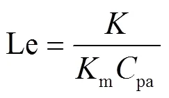


式中a,s为空气和溶液焓值,kJ/kg;e为与溶液平衡空气焓值,kJ/kg;为水汽化潜热,kJ/kg;1为溶液与空气的流向系数,其中顺流为-1,逆流为1;2为热水的流向系数,热水流向与溶液相同(流向Ⅰ)时为-1,相反(流向Ⅱ)时为1;为刘易斯数;a为空气含湿量,kg/kg;e为与溶液平衡空气含湿量,kg/kg;w,s为热水和溶液温度,℃;a,w,salt为空气、热水和溶液中盐分质量流量,kg/s;pa,pw为空气和热水比热,kJ/(kg·K);为水盐比,kg/kg;为空气和溶液间传热系数,kW/(m2·K);w为热水和溶液间传热系数,kW/(m2·K);m为空气和溶液间传质系数kg/(m2·s);1为溶液和空气接触面积,m2;2为溶液和热水接触面积,m2;NTU1为溶液和空气间的传热单元数;NTU2为溶液和热水间的传热单元数。
式(9)-式(13)为叉流热湿交换数学模型。


式中为溶液流动方向;为空气流动方向;为再生装置高度,m;为再生装置长度,m。
1.2 预热型再生模型
再生器为预热型时,相当于将内热型中的热水和溶液传热单元数(NTU2)移到装置外构成预加热器,因此在模型建立中,只需要将上述内热型模型中的NTU2设置为0,而再生器的入口溶液受预热器加热作用温度升高。假设预热再生器入口溶液与热水在预热器中进行逆流换热,换热器效能由公式(14)得出,则再生器的溶液入口温度可经公式(15)计算得到。

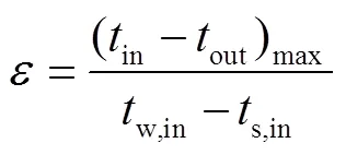
式中为换热效率;(p)max,(p)min分别为流体质量流量和比热乘积的最大和最小值,kW/℃;in,out分别为流体进出口温度,℃;w,in,s,in,分别为热水和溶液进口温度,℃。
2 模型验证
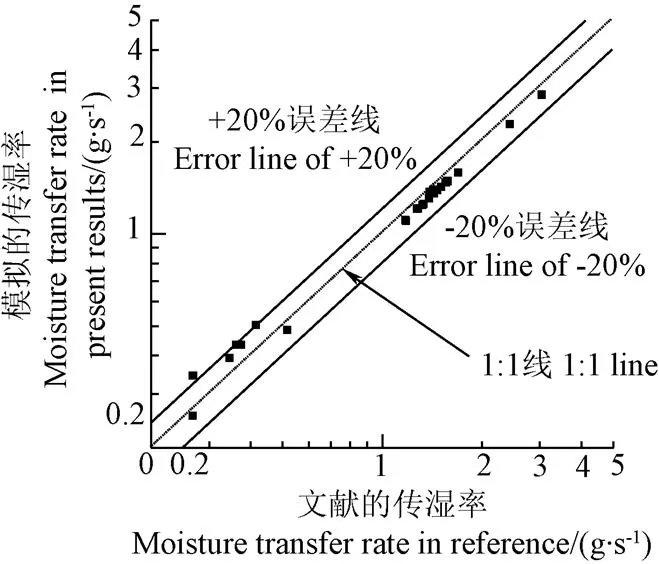
为验证预热和内热溶液再生模型的精确性,将文献[24-27]中通过试验及理论得到的57个传湿率(蒸发率或除湿率)结果作为对比参数,其中规整填料和散装填料的形状参数计算方法在文献[28-29]中给出,溶液物性参数根据文献[30]中给出的计算方式进行计算。文献中的溶液、空气和水的初始参数如表1所示。图2对比了文献和本文数值模拟的传湿率,其中图2a为模拟的蒸发率与文献[24,27]给出的预热型逆流及叉流再生试验数据的结果对比;图2b为模拟的蒸发率及除湿率与文献[25-26]分别给出的内热/冷型逆流理论解及叉流内热再生试验数据的结果对比。其中文献[25]中还对比了内冷除湿率的结果,虽不是再生结果,但采用相同的理论模型也能验证模型的精确性。由图2可以看出,模拟数据和对比数据之间误差除去1个数据点外,均在20%的误差范围内,平均误差为8.6%。考虑到试验仪器和测量上的误差,一般工程上20%的误差在可接受范围内[31],验证了模拟程序的精确性。

表1 对比文献的流体入口参数

a. 预热模型
a. Pre-heated model
b. 内热模型
b. Internally heated model
注:图2a的蒸发率的数据来自文献[24]和[27];图2b的蒸发率及除湿率的数据来自文献[25]和[26];图中横纵坐标均为对数坐标。
Note: Evaporativity data of Fig.2a is from Refs. [24] and [27]; Evaporativity and dehumidificativity data of Fig.2b is from Refs. [25] and [26]. The-axis and-axis are logarithmic coordinate.
图2 数值模型的精确性验证
Fig.2 Validation of numerical model
3 两种溶液再生方式性能比较
为研究内热和预热2种不同的溶液再生方式对再生器再生性能的影响,文章针对溶液和空气呈顺流、逆流、叉流3种流型及热水和溶液分别处于同向(流向Ⅰ)和反向(流向Ⅱ)的6种不同组合情况进行模拟,并与相应情况下的预热结果进行比较。各模拟工况所选择的参数范围见表2,表中给出19组初始参数,结合内热型再生的6种流型及预热型再生的3种流型组合共计得到171个模拟结果,如图3所示。模拟中、、a分别为0.4、0.5 m和1 kg/s。模拟结果显示大部分工况下内热型再生器的溶液出入口浓度差是预热型的2~4倍,即内热型再生器表现出明显的性能优势。这是由于预热型再生器中溶液的温度会随着热湿交换的发生而下降,而溶液温度的下降影响着装置的再生性能。内热型再生器由于热水与溶液的热交换及溶液与空气的热湿交换同时进行,能一定程度上抑制温度下降,使溶液与热水的温度势差更均匀。仅当s/a以及w/a在一定范围内变化时,部分工况的预热型再生器优于内热型再生器。
为进一步了解内热和预热再生性能受溶液与空气流量比以及热水与空气流量比的影响,文章分析溶液-空气质量流量比(s/a)从0.1上升至0.65,热水-空气流量比(w/a)从0.4上升至0.95的范围中,溶液和空气顺流,且热水自下而上流动(流向Ⅱ)时,内热型再生器与预热型的出入口浓度差比值,见图4所示。模拟中参数取如下基准值:热水空气流量比w/a=0.7,溶液空气流量比s/a=0.2;空气入口温度a, in=30 ℃、溶液入口温度s, in=27 ℃,热水入口温度w, in=80 ℃;空气入口含湿量a, in=0.012kg/kg,溶液入口水盐比in=1.85 kg/kg;溶液空气间传热单元数NTU1=0.5,溶液热水间传热单元数NTU2=0.9。
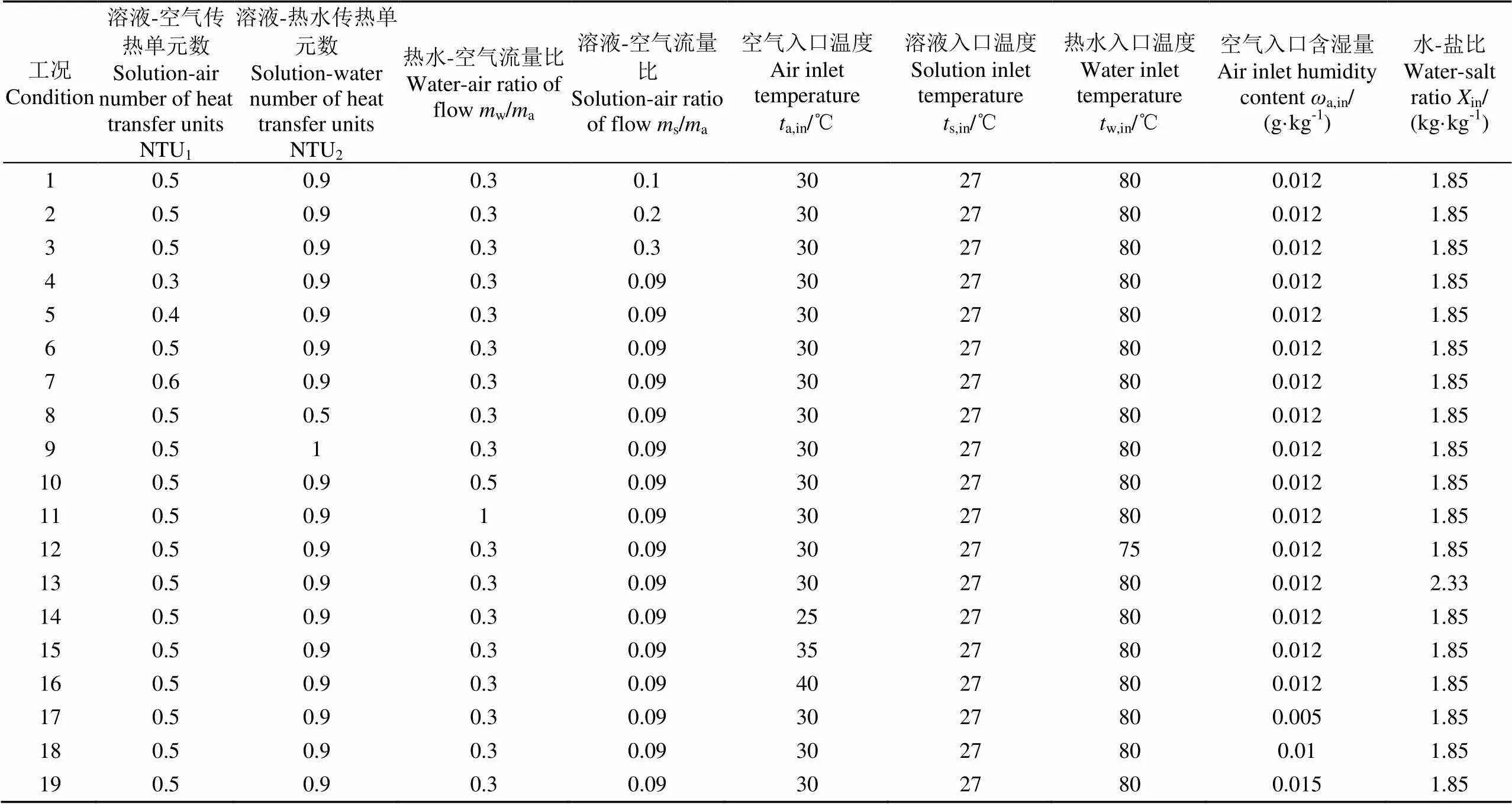
表2 不同工况所选择的初始参数
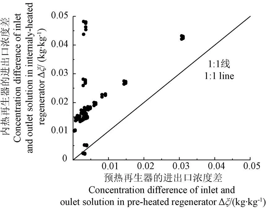
注:图中数据包含内热型及预热型再生中的溶液与空气在顺、逆、叉3种不同流向下的比较,其中内热型再生包含2种热水流向(流向Ⅰ和流向Ⅱ);长度L=0.4 m;高度H=0.5 m;空气质量流量ma=1( kg·s-1),下同。
预热溶液的出口温度逐渐升高并趋于一个定值,但溶液总体的所得热能大幅下降,而整体的流量下降也导致在热湿交换中温度下降更快,再生能力变差。而在内热装置中,由于溶液流量的减小,其入口段温升越快,再生段的长度增加,再生能力增强。即使热水流量持续增加,预热型再生器中再生溶液的温度增加到一个定值后便不再递增,随后再生溶液进入再生器中进行再生过程时,由于热湿传递使得溶液温度下降较大,再生能力也大幅下降。而内热型再生器中的再生溶液依靠大流量的热水保持温度基本稳定,且随着热水流量增加,溶液温度基本与热水温度相等,这就使得溶液一直保持着较好的再生性能。
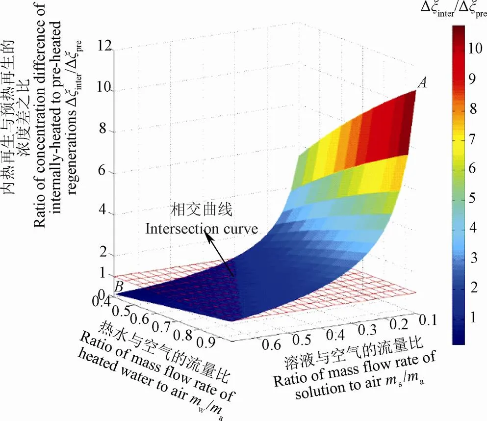
注:溶液和空气顺流;热水自下而上流动(流向Ⅱ);模拟中参数基准值:ta, in=30 ℃、ts, in=27 ℃,tw, in=80 ℃;ωa, in=0.012 (kg·kg-1),Xin=1.85 (kg·kg-1);NTU1=0.5,NTU2=0.9,下同。A点为内热最大点 (A:mw/ma=0.95, ms/ma=0.1); B点为内热最大点 (B:mw/ma=0.65, ms/ma=0.4)
图中显示随着s/a减小以及w/a增加,内热型再生器具有更好的性能。即单位空气流量下,溶液流量越小,或是热水流量越大,内热型再生器相对于预热型再生器的再生性能越好。这是由于随着溶液流量的减小,由图4可知,在给定的模拟范围内,内热型再生器的溶液出入口浓度差最高可达到预热的10.85倍,最低仅有预热的0.15倍。将图中的交界线拟合成曲线,得到内热效果较好的工况,流量比之间满足关系式(s/a)<(0.628 6w/a−0.055 9)。另外,通过计算蒸发率,得到该模拟范围内的内热最大值点(:s/a=0.1,w/a=0.95)时,溶液中的水蒸发率为0.0105kg/s,得到该模拟范围内的预热最大值点(:s/a=0.4,w/a=0.65)时,溶液的水蒸发率仅为5.29×10-4kg/s,即内热最佳点的蒸发量是预热的19.84倍,内热型再生器明显优于预热型。因此,选用内热型再生方式进行研究。A、B两点分别为基于NTU1和NTU2的基准值模拟得到,其随NTU1与NTU2的变化规律将在下文研究中阐述。
4 内热型溶液再生器性能分析
影响内热型溶液再生器性能的因素包括各种流体流型和传热单元数。流型主要有热水流动方向、溶液和空气相对流动方向。传热单元数是基于溶液、空气和热水三者间传热系数和传热面积的综合变量。下文针对这3个因素对内热型再生的性能(溶液进出口浓度差)进行影响分析。
4.1 热水流向对内热再生性能的影响
图5中展示了内热型再生器在不同热水流向下溶液出入口浓度差的变化情况。
由图5可以看出,热水的流向影响比较小,但是总体上流向Ⅱ要优于流向Ⅰ,溶液与空气呈顺流、逆流、叉流时均满足此规律,且在顺流工况下流向Ⅱ相对流向Ⅰ表现更优,其再生性能最大可提高5%。这是由于在热水与溶液逆向流动的过程中,其传热温差比较稳定,所以传热效果更理想。

图5 热水流向Ⅰ和流向Ⅱ对再生性能的影响
4.2 传热单元数对内热再生性能的影响
传热单元数受装置传热面积和装置内流体间传热系数变化的影响,是一种影响性能的重要因素。在内热型再生器中,溶液与空气间的传热单元数(NTU1)以及热水与溶液间的传热单元数(NTU2)是反映溶液和空气间及溶液和热水间的传热面积和传热系数的综合影响因素,是影响装置热湿交换性能的2个关键性参数。
图6为NTU1和NTU2对溶液出入口浓度差的影响,其中NTU1和NTU2均在0.2到1.65之间变化。

图6 不同NTU对顺流内热再生器出入口浓度差的影响


4.3 顺、逆、叉流对内热再生性能的影响
为比较溶液与空气在顺流、逆流、叉流3种再生方式下的再生效果,图6b绘制了逆流与顺流浓度差比以及叉流与顺流浓度差比变化的2种情况。由图可以看出,整体上,顺流最优,逆流其次,叉流最差。但在NTU1偏大且NTU2极小时(NTU1大于0.7,NTU2小于0.4),逆流优于叉流;特别是当NTU2小于0.35,NTU1大于1.45时,逆流与顺流比高于1,逆流优于顺流,但最高仅达到1.03优势不明显。叉流与顺流之比大部分处于0.97,当NTU2小于0.5时叉流与顺流的浓度差之比下降到0.88;而逆流与顺流的浓度差之比的曲面呈现马鞍状,当NTU1与NTU2均小于0.7或均大于1.5时,逆流与顺流的浓度差之比均下降至0.87。随着基准点的变化,对具体浓度差会有一定的影响,但总体趋势不变。
为分析在模拟范围内大部分工况下顺流最优的原因,本节对于模拟范围内顺流最优工况(工况:NTU1=1.2,NTU2=0.8)和逆流优势工况(工况:NTU1=1.8,NTU2=0.2)进行溶液与空气含湿量变化趋势研究,分别见图7a和7b。图中同一流向中溶液与空气含湿量的交点表示由除湿过程转变至再生过程的NTU1位置,称为临界点,内热再生过程中到达临界点的先后决定了该过程的再生性能优劣。由图可看出工况中顺流的临界点比逆流提前,即提前进入再生状态,而工况中逆流临界点靠前,即逆流更快到达再生状态。分析2种工况下溶液与空气含湿量可得到流体流动过程中的平均含湿量,以及得到溶液和空气的含湿量差值。工况中,逆流含湿量差为5.85 g/kg,小于6.19 g/kg顺流含湿量差;而工况中,逆流含湿量差为0.21 g/kg,大于0.207 g/kg顺流含湿量差。含湿量差越大意味着传质驱动力越大,在相同传热单元数下,再生性能越好。上述结果解释了图6b所呈现的结果。工况中的含湿量差远大于工况中的含湿量差,这说明在顺流工况下再生性能优于逆流工况下再生性能。

注:图中为顺流最优工况(工况Ⅰ:NTU1=1.2,NTU2=0.8)。
Note: Parallel type is in the best condition in the figure (Condition Ⅰ: NTU1=1.2, NTU2=0.8).
a. 顺流为优势流型的情况
a. Parallel type in best condition
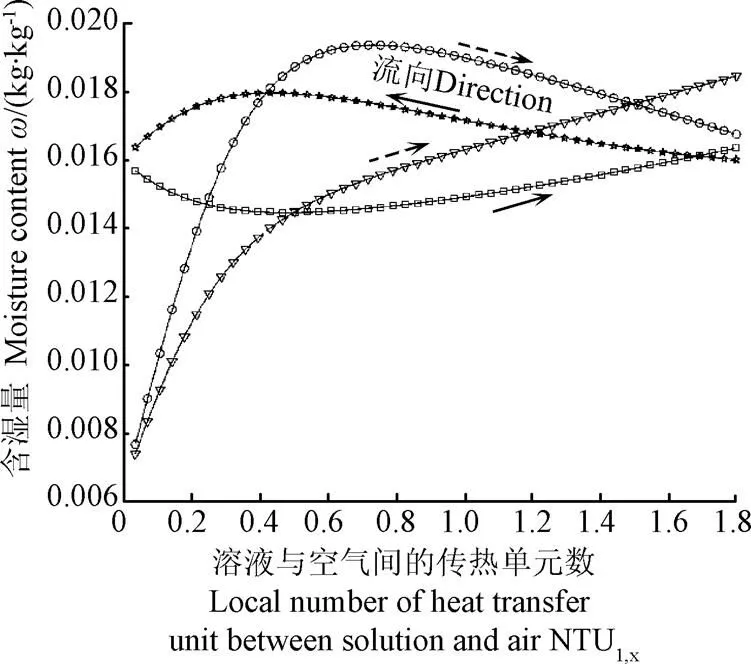
注:图中为逆流最优工况(工况Ⅱ:NTU1=1.8,NTU2=0.2)。
Note: Counter type is in the best condition in the figure (Condition Ⅱ: NTU1=1.8, NTU2=0.2).
b. 逆流为优势流型的情况
b. Counter type is best condition
图7 2种优势流型下溶液与空气含湿量变化趋势
Fig.7 Change of moisture content of solution and air under two kinds of flow types
5 结 论
文章基于溶液、空气以及热水的三者间能量和质量守恒,建立基于传热单元数的预热、内热再生器在2种热水流向下的顺流、逆流、叉流的数学模型,分析不同装置结构对再生性能的影响,得到如下结论:
1)文章在分析预热及内热结构对再生性能的影响时,发现大部分工况下内热型再生器的溶液出入口浓度差是预热型的2~4倍,即内热型再生器表现出明显的性能优势。且整体受流量比影响,随着溶液-空气流量比减小以及热水-空气流量比增加,内热型再生器相对于预热型再生器的再生性能越好。
2)在研究热水的流向对再生性能的影响时,发现热水流向对装置性能影响比较小,但是总体上热水与溶液流向相反时要优于相同时,两者浓度差最大可达到5%。
3)在分析传热单元数对再生性能的影响时,发现当溶液-热水传热单元较小时(0.2~0.35)再生效果随着溶液-空气流量比的增加,呈现先增加后减少的趋势,当溶液-热水传热单元较大时(大于0.35)浓度差随着溶液-空气流量比的增加先增长然后逐渐趋于稳定。总体上当空气与溶液处于顺流状态时,再生效果最优,仅当溶液-空气流量比大于0.7,溶液-热水传热单元小于0.4时,空气与溶液处于逆流的再生效果优于叉流;当溶液-热水传热单元小于0.35,溶液-空气流量比大于1.45时逆流优于顺流。
[1] Jain S, Tripathi S, Das R S. Experimental performance of a liquid desiccant dehumidification system under tropical climates[J]. Energy Conversion and Management, 2011, 52(6): 2461-2466.
[2] Liu J, Liu X H, Zhang T. Performance comparison of three typical types of internally-cooled liquid desiccant dehumidifiers[J]. Building and Environment, 2016, 103: 134-145.
[3] Luo Y, Wang M, Yang H X, et al. Experimental study of internally cooled liquid desiccant dehumidification: Application in Hong Kong and intensive analysis of influencing factors[J]. Building and Environment, 2015, 93: 210-220.
[4] Katejanekarn T, Chirarattananon S, Kumar S. An experimental study of a solar-regenerated liquid desiccant ventilation pre-conditioning system [J]. Solar Energy, 2009, 83(6): 920-933.
[5] Kabeel A E. Augmentation of the performance of solar regenerator of open absorption cooling system[J]. Renewable Energy, 2005, 30(3): 327-338.
[6] Audah N, Ghaddar N, Ghali K. Optimized solar-powered liquid desiccant system to supply building fresh water and cooling needs[J]. Applied Energy, 2011, 88(11): 3726-3736.
[7] Guo Y, Ma Z, Al-Jubainawi A, et al. Using electrodialysis for regeneration of aqueous lithium chloride solution in liquid desiccant air conditioning systems [J]. Energy and Buildings, 2016, 116: 285-295.
[8] Cheng Q, Xu Y, Zhang X S. Experimental investigation of an electrodialysis regenerator for liquid desiccant[J]. Energy and Buildings, 2013, 67: 419-425.
[9] Abdel-Salam M R H, Besant R W, Simonson C J. Performance testing of a novel 3-fluid liquid-to-air membrane energy exchanger (3-fluid LAMEE) under desiccant solution regeneration operating conditions[J]. International Journal of Heat and Mass Transfer, 2016,95: 773-786.
[10] Patel H, Ge G, Abdel-Salam M R H, et al. Contaminant transfer in run-around membrane energy exchangers[J]. Energy and Buildings, 2014, 70: 94-105.
[11] Zhang T, Liu X, Jiang J, et al. Experimental analysis of an internally-cooled liquid desiccant dehumidifier[J]. Building and Environment, 2013, 63: 1-10.
[12] 常晓敏,刘晓华,江亿. 内冷型溶液除湿器的热质交换分析及流型比较研究[J]. 太阳能学报,2009,30(2):170-176.
Chang Xiaomin, Liu Xiaohua, Jiang Yi. Research in the heat and mass transfer performance and flow-pattern comparosion of the internally-cooled liquid desiccant dehumidifiers[J]. Acta Energiae Solaris Sinica, 2009, 30(2): 170-176. (in Chinese with English abstract)
[13] Fumo N, Goswami D Y. Study of an aqueous lithium chloride desiccant system: Air dehumidification and desiccant regeneration[J]. Solar Energy, 2002, 72(4): 351-361.
[14] Kim M H, Park J Y, Jeong J W. Simplified model for packed-bed tower regenerator in a liquid desiccant system[J]. Applied Thermal Engineering, 2015, 89(5): 717-726
[15] Longo G A, Gasparella A. Experimental analysis on desiccant regeneration in a packed column with structured and random packing[J]. Solar Energy, 2009, 83(4): 511-521.
[16] Mun J H, Joen D S, Kim Y L, et al. A study on the regeneration performance characteristics of an internally heated regenerator in a liquid desiccant system[J]. Journal of Mechanical Science and technology, 2016, 30(3): 1343-1349.
[17] Liang C H, Wen X T, Liu C X, et al. Performance analysis and experimental study of heat-source tower solution regeneration[J]. Energy Conversion & Management, 2014, 85: 596-602.
[18] Yin Y G, Zhang X S, Peng D G, et al. Model validation and case study on internally cooled/heated dehumidifier/ regenerator of liquid desiccant systems[J]. International Journal of Thermal Sciences, 2009, 48(8): 1664-1671.
[19] Yin Y G, Zhang X S. Comparative study on internally heated and adiabatic regenerators in liquid desiccant air conditioning system[J]. Building and Environment, 2010, 45(8): 1799-1807.
[20] Luo Y M, Yang H X, Lu L, et al. A review of the mathematical models for predicting the heat and mass transfer process in the liquid desiccant dehumidifier[J]. Renewable & Sustainable Energy Reviews, 2014, 31: 587-599.
[21] Liu J, Zhang T, Liu X, et al.Experimental analysis of an internally-cooled/heated liquid desiccant dehumidifier/ regenerator made of thermally conductive plastic [J]. Energy and Buildings, 2015, 99: 75-86.
[22] Qi R H, Lu L. Energy consumption and optimization of internally cooled/heated liquid desiccant air-conditioning system: A case study in Hong Kong [J]. Energy, 2014, 73(7): 801-808.
[23] Qi R H, Lu L, Yang H X. Development of simplified prediction model for internally cooled/heated liquid desiccant dehumidification system[J]. Energy and Buildings, 2013, 59: 133-142.
[24] Longo G A, Gasparella A. Experimental and theoretical analysis of heat and mass transfer in a packed column dehumidifier/regenerator with liquid desiccant[J]. International Journal of Heat and Mass Transfer, 2005, 48(25/26): 5240-5254.
[25] Ren C Q, Tu M, Wang H H. An analytical model for heat and mass transfer processes in internally cooled or heated liquid desiccant-air contact units[J]. International Journal of Heat and Mass Transfer, 2007, 50(17/18): 3545-3555.
[26] Bansal P, Jain S, Moon C. Performance comparison of an adiabatic and an internally cooled structured packed-bed dehumidifier [J]. Applied Thermal Engineering, 2011, 31(1): 14-19.
[27] Zhang L, Hihara E, Matsuoka F, et al. Experimental analysis of mass transfer in adiabatic structured packing dehumidifier/ regenerator with liquid desiccant[J]. International Journal of Heat and Mass Transfer, 2010, 53(13/14): 2856-2863.
[28] Al-Farayedhi A A, Gandhidasan P, Al-Mutairi M A. Evaluation of heat and mass transfer coefficients in a gauze-type structured packing air dehumidifier operating with liquid desiccant[J]. International Journal of Refrigeration, 2002, 30: 330-339.
[29] Treybal R E. Mass-Transfer Operations/ -3rd ed[M]. New York:McGraw-Hill, 1980.
[30] Conde M R. Properties of aqueous solutions of lithium and calcium chlorides: Formulations for use in air conditioning equipment design[J]. International Journal of Thermal Sciences, 2004, 43(4): 367-382.
[31] 杨世铭,陶文铨. 传热学[M]. 北京:高等教育出版社,2006.
Analysis of performance and regeneration method of internally-heated liquid desiccant regenerator
Peng Donggen, Luo Danting, Li Shunyi
(,,330031,)
Liquid desiccant cooling system, as a good alternative to traditional electric refrigeration air conditioner, is environmentally friendly and can be driven by low-grade energy while it can improve indoor air quality and has high energy storage capacity. The regeneration technique,a key technique in the liquid desiccant cooling system,must be developed before it is widely applied in variety of buildings. The present methods of solution regeneration have electrodialysis, membrane energy exchanger, ultrasonic atomization regeneration, packing tower, and so on. The first three have complicated structures and high costs for their application on a large scale. The packing tower regenerator because of its simple structure and being driven possibly by low-grade energy has attracted many attentions across the world. In packing tower regenerators, the internally-heated liquid desiccant regenerator is a kind of high-efficient solution regeneration device. To improve the reliability and economy of internally-heated regeneration technique, the mathematical models of pre-heated and internally-heated regeneration are established based on the energy and mass conservation between solution and air as well as the energy conservation between heated water and solution in this paper, which include parallel flow, counter flow and cross flow with 2 kinds of different flow directions of heated water respectively, and their theoretical performances are numerically simulated and compared with each other. As for the regeneration performances affected by the ways of heating solution and flow directions of heated water, the simulation results show that regeneration performances of internally-heated type are about 2-4 times that of pre-heated type in most conditions, which means the internally-heated regenerator has a better performance. And the regeneration performances are greatly influenced by the flow-rate ratios of solution to air and heated water to air. With the decrease in flow-rate ratio of solution to air and the increase in flow-rate ratio of heated water to air, the regeneration performances of the internally-heated regenerator are increasingly better than that of the pre-heated regenerator. At the maximum point of the internally-heated (flow-rate ratio of solution to air is 0.1 and flow-rate ratio of heated water to air is 0.95, flow-rate ratio of air is1 kg/s), the rate of evaporation is calculated to be 20 times that of the pre-heated at its maximum point (flow-rate ratio of solution to air is0.4, flow-rate ratio of heated water to air is0.65). The flow direction of heated water in internally-heated regenerator is divided into 2 conditions: Heated-water is parallel to solution (DirectionⅠ) or counter to solution (DirectionⅡ). It is also found the regeneration performances, when the heated water flows counter to solution, are superior to heated water paralleling to solution and are increased by 5% at most. As for the effects of the numbers of heat transfer units (NTU1andNTU2), the regeneration performances in general increase with the increase in NTU1and NTU2, and a fitted curve combining NTU1with NTU2occurs that presents the rapidest increase in regeneration performance with the increasing of NTU1and NTU2. Besides, it is also exposed that parallel type shows the largest concentration difference of solution and the cross type is about 97% of that, while the counter type only reaches about 87% as much as parallel type in the worst condition. The results in this paper can offer theoretical supports for the optimal design of internally-heated regenerator.
models; regenerators; concentration; internally-heated; performance; numbers of heat transfer units
10.11975/j.issn.1002-6819.2017.18.022
TU831.6
A
1002-6819(2017)-18-0165-08
2017-05-24
2017-08-07
国家自然科学基金项目(51766010);江西省研究生创新专项资金项目(YC2017-S012)
彭冬根,男,博士,副教授,主要从事太阳能制冷空调研究。南昌 南昌大学建筑工程学院,330031。Email:ncu_hvac2013@163.com

