
Mechanical Behavior Analysis for Unbonded Umbilical under Axial Loads
2017-06-22 14:44:18GUOYousongCHENXiqiaFUShixiaoWANGDe
船舶力学 2017年6期
GUO You-song,CHEN Xi-qia,FU Shi-xiao,WANG De-yü
(1.State Key Laboratory of Ocean Engineering,Collaborative Innovation Center for Advanced Ship and Deep-Sea Exploration,Shanghai Jiao Tong University,Shanghai 200240,China;2.Tianjin Branch, CNOOC Ltd,Tianjin 300452,China)
Mechanical Behavior Analysis for Unbonded Umbilical under Axial Loads
GUO You-song1,CHEN Xi-qia2,FU Shi-xiao1,WANG De-yü1
(1.State Key Laboratory of Ocean Engineering,Collaborative Innovation Center for Advanced Ship and Deep-Sea Exploration,Shanghai Jiao Tong University,Shanghai 200240,China;2.Tianjin Branch, CNOOC Ltd,Tianjin 300452,China)
To investigate the mechanical behavior of the unbonded umbilical and to improve the structural design,an analytical model to predict the tension behavior is proposed.The governing equation of the model provides the solution for the tension load-elongation relationship considering the effect of diameter reduction of armor layers.A finite element model of a given unbonded umbilical is established to supply the value of armor diameter reduction for analytical model and to determine the stress distribution in the umbilical.Tension stiffness tests of the given unbonded umbilical are carried out and a good agreement among analytical model,finite element model and experimental results is shown.Based on the analytical model,a parametric study is conducted to understand the effect of radial reduction on the tension stiffness.Furthermore,the fatigue analysis of the unbonded umbilical under design tension loading cases is also conducted.
unbonded umbilical;tension;stiffness tests;effect of radial reduction; numerical model;fatigue
0 Introduction
Multi-layered unbonded umbilicals are widely used in offshore production,conveying fluid,signals and power between well-heads and offshore rigs.In their serving life,unbounded umbilicals have to undergo load combinations induced by current,waves,vortex-induced vibrations and the motion of floating vessels.To ensure their safety,it is indispensable to accurately assess the load conditions,the stress distribution and the fatigue life of the umbilicals at the design stage.Hence,an analytical model and a finite element model to predict the tension stiffness and stress distribution are of great importance.
The problems of predicting the structural response in similar multilayer structures have been dealt with by many researchers.KNapp[1]derived a stiffness matrix for multi-layered cables subjected to tension and torsion.Feret and Bournazel[2]took each layer of flexible pipeas an independent element and formulated the governing equations of flexible pipe axisymmtric behavior.Ramos and Pesce[3]extended Feret’s model and provided a more general one for flexible pipe subjected to combined loads.Ramos et al[4]presented axial-torsional behavior tests of flexible pipe to validate the proposed analytical model and good agreements have been shown.Witz and Tan[5]presented expressions to predict axial-torsional behavior expression for multi-layered structural based on Love’s curved beam theory and discussed a case study. Claydon et al[6]studied the unbonded flexible pipe response under cyclic loading conditions. As mentioned above,many theoretical models are presented in the literature to predict the behavior of flexible pipes under tension load,but few of them can provide accurate estimation for umbilicals due to the effect of armor layer diameter reduction.The diameter reduction caused by core compression and filling of the cusp space is difficult to calculate analytically and should be obtained from finite element analysis or experiment tests.
The proposed analytical models are quite complicated and their range of application is limited by the simplified assumptions on which they are based.This motivated researchers to develop refined finite element model.Zhang and Tuohy[7]studied the application of FEM in the analysis of large diameter unbounded flexible riser.They utilized an equivalent material and geometric properties to model the contact between layers,but the contact surface friction and end-fitting effects were not considered in the model.Bahtui et al[8]developed a finite element model to study the response of unbounded flexible riser under axial tension.The numerical results had compared with the analytical results obtained from several analytical methods and a good agreement had been found.Vaz and Rizzo[9]developed an axisymmetric model to estimate the critical instability and failure modes.The model was constructed by employing a complex combination of beam and spring elements.Although researchers have conducted a significant amount of research on the finite element analysis of flexible pipe,few of them extended it to umbilicals.
Taking the radial reduction of armor layer into consideration,an analytical model is presented to predict the tension behavior of unbounded umbilical.The governing equation provides the tension load-elongation relationship and a parametric study of radial reduction is conducted based on it.A finite element model of a given unbounded umbilical is established in general software to supply the value of radial reduction for the analytical model.Prototype tests of the tension stiffness of the given unbounded umbilical were carried out to validate the analytical and the finite element model.Finally,the fatigue analysis of the given umbilical under design loads is conducted and it is found that the design tension loads contribute little to the fatigue damage of the umbilical.
1 Analytical model
Umbilical is a complex structural composed by different components,among them,tensile armors are in helical configuration,which makes it difficult to analyze the tension behav-ior for the whole structural.Taking the tensile armors as the analysis objects,the structural axial strain is derived and then the tension stiffness is obtained based on Hook’s law.Several assumptions must be made to develop the analytical model.
(1)All of the layers have the same elongation under tension load.
(2)All of the materials are assumed to respond in the linear elastic range.
(3)There is no gap between adjacent layers.
(4)All the deformation of the components is assumed to be small.
(5)The axial strain and stress of all the components are assumed to distribute uniformly.
Unfolding the helical laying tensile armor,the geometric relations between the axial elongation and radial reduction are shown in Fig.1.
According to the geometric relationship between the original and deformed shapes as illustrated in Fig.1,the axial strain in the elongated helical armor can be written as


Fig.1 Helical geometry of a helical armor
where a and a′are the length of the helical armor before and after the elongation respectively,and can be expressed as:
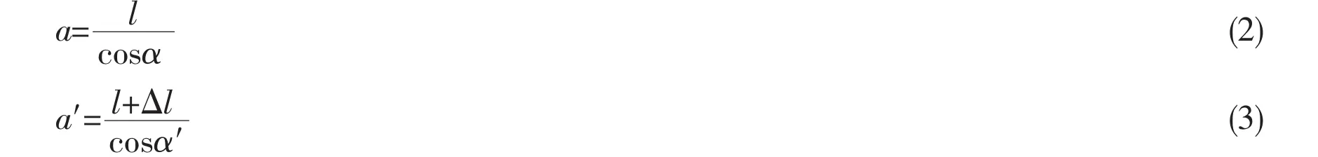
According to Fig.1,the lay angle after the elongation can be expressed as

where l denotes the length of the umbilical;R and△R denote the lay radius and radius reduction of the helical armor,respectively.
Substituting Eqs.(2)-(4)into Eq.(1),we have

Neglecting the second-order strain quantities,Eq.(5)can be linearized as

According to the Hooke’s law,we have

where σ,F and E denote the axial stress,axial force and the material elastic modulus of the helical armor,respectively.
Projecting the axial force of the helical armor onto the axes of the umbilical,the force contribution from the helical armor to the total axial force of the umbilical can be further deduced.

Combing the expressions of the straight component axial force with Eq.(9),the total axial force F of the umbilical can be deduced.

where EiAidenotes the axial stiffness of helical armor i;αidenotes the lay angle of helical armor i;n denotes the number of helical armors;EjAjdenotes the axial stiffness of straight component j;m denotes the number of straight components.
The axial stiffness K of the umbilical can further be derived from Eq.(10)as

where ν denotes the ratio of radial reduction,which can be expressed as

2 Finite element model
A very detailed finite element model of a given umbilical is developed in general finite element software to obtain the structural behavior under tension loads and to provide the value of radial reduction of armor layer for the analytical model.
As shown in the Fig.2,the 1.8 m model consists of 6 separate cylindrical components, located one into another as layers of the umbilical.There are two tube layers,two sheath layers and two armor layers.The geometric parameters and material properties are listed in the Tab.1.

Fig.2 Finite element model of the given unbounded umbilical
The umbilical is modeled by 3D,8-node linear brick,reduced integration elements with hourglass control,which allows much more accurate contact analysis.Contact elements are defined between each layer and the contact analysis is based on the Coulomb friction model to-gether with the general contact algorithm. The coefficient of friction between layers is assumed to be 0.1,as given in the experimental results[10].A well distributed mesh containing 307 246 elements and 446 863 nodes is utilized to keep the artificial energy well below 5%of the stain energy.
The ends of each side of all layers are connected rigidly to two reference nodes at the centre of each cross section.All boundary conditions for both ends are then applied to these two reference nodes only,as shown in Fig.3. In order to obtain stable solution for such complicated contact problems,the explicit solver is used with 5e-7sec time increment.
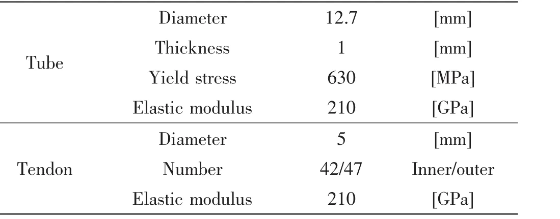
Tab.1 Geometric parameters and material properties of the given unbounded umbilical

Fig.3 The schematic diagram of boundary and load conditions
As illustrated above,the finite element analysis is conducted and the stress contour plot of the umbilical is shown in Fig.4.
As shown in Fig.4,the stress in each layer distributes uniformly,which proves the validity of assumption 5.The stress in the tube layer is much larger than that in armor layer,which can be accounted for by the fact the lay angle of tube layer is larger than the armor layer’s and the stress response is larger with bigger lay angle,as illustrated by Eq.(7).
Comparing the stress in the two armor layers with the same lay angle,the stress in the inner layer is larger than that of outer layer.The fact is because that the radial reduction of outer layer is more notable than the inner layer’s and the radial reduction can reduce the stress response as shown by Eq.(7).As the axial force is dominated by the cross-section area and the axial stress,the tension stiffness contributed from inner layer is bigger than that from the outer layer.And we candraw a conclusion that the radial reduction not only affects the value of the stiffness but also changes the distribution of stiffness in the umbilcial.

Fig.4 Axial-stress contour plot for the whole given umbilical
Extract the node locations of armor layers before and after deformation,the radial reduction of the two armor layers can be calculated in the coordinated system of Fig.3
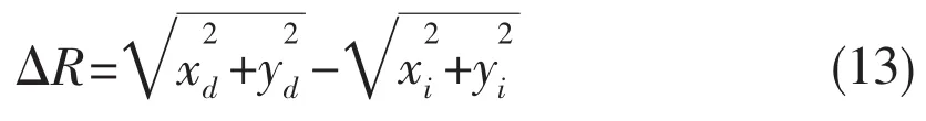
where xiand yidenote the x and y node coordinate of initial configuration;xdand yddenote the x and y node coordinate of deformed configuration.
The curves of relationship between the axial strain and average value of radial reduction of inner armor and outer armor are shown in Fig.5.
As shown in Fig.5,the axial strain and the radial reduction are in linear relation.The radial reduction of outer armor layer is lager than that of inner armor layer,which can explain the fact that the stress in the inner layer is larger than that of outer layer.The results of the calculated radial reduction can be applied to the analytical model for further stiffness analysis.
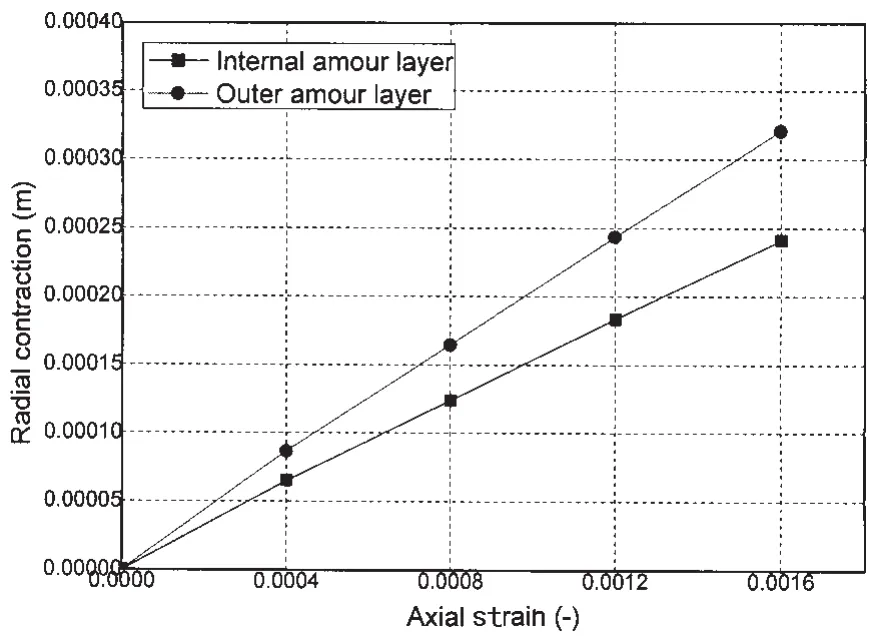
Fig.5 The relationship curves between the axial strain and the radial reduction
3 Verification and sensitive analysis of the model
Tension behavior tests of the given umbilical were carried out to verify the developed analytical model and finite element model in this paper.The average results of the tests are shown in Fig.6,compared with the analytical and FEM results.
From the figure,we can see that the FEM results agree well with the experiment results, from which we can draw a conclusion that the FEM can provide a good prediction of the tension behavior for the umbilical and this FEM can be used to conduct fatigue analysis of the umbilical.
Comparing the analytical results without radial reduction with the experiment results,we can find out that the analytical results overestimate the tension stiffness of the umbilical,being almost 2.7 times of the experiment results.Taking the radial reduction results in Fig.5 into Eq.(11),the modified analytical results satisfy well with the experiment results,which prove the fact that the radial reduction has a great effect on the tension stiffness and cannot be neglected.

Fig.6 The comparison of tension stiffness results
Based on the developed analytical model,the sensitive analysis of radial reduction on the tension stiffness is conducted.According to Eq.(11),the tension stiffness can be expressed as a function of the radial reduction as shown in Eq.(13)

For convenience to analysis,assuming that both the two armor layers are of the same radial reduction,then the values of the umbilical tension stiffness with different radial reduction ratio are calculated and listed in Tab.2.
From the calculated results,we can find out that the stiffness of the whole umbilical decreases with the increasing radial reduction and the main stiffness contribution transfers from armor layers to tube and sheath layers.Without radial reduction,most of the umbilical tension stiffness is provided by armor layers.However,with 4.5 radial reduction ratio,the tube and sheath layers contributed much more than the armor layers to.The above facts illustrated that the radial reduction affects the load distribution ratio and attention should be paid to when conducting stress analysis on certain layer.

Tab.2 The calculated tension stiffness with different radial reduction ratio
The relationship between the tension stiffness and the lay angle with and without radial reduction ration is shown in Fig.7.Different lay angles from 0°to 25°are set in this model.
As shown in Fig.7,the tension stiffness results with and without radial reduction decrease with the increasing lay angle,which prove that the stiffness is a decreasing function of the lay angle.Comparing the two relationship curves,we can find out that the influence of radial reduction on the tension stiffness becomes less with smaller lay angle.
4 Fatigue analysis
Based on the developed FEM,the fatigue analysis of the given umbilical is conducted.Thedesign fatigue tension load in 0.5 hour is shown in Fig.8 according to Ref.[11].
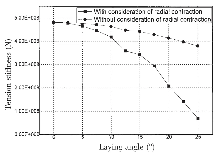
Fig.7 The relationship curves between the lay angle and the tension stiffness
As shown in Fig.8,the horizontal and vertical coordinates stand for minimum and maximum tension load respectively.The tension range of a certain point is the difference between its vertical and horizontal coordinate.The counted cycles of certain tension range is represented by the color in the figure.Among the data in the figure,the minimum tension range is at (233.4,233.5)to be 0.1 kN and the maximum tension range is at(230.1,236.4)to be 6.3 kN. The cycles of tension range decrease from 194 to 1with the increasing tension range.

Fig.8 The tension load ranges and their cycles
Taking the load conditions in Fig.8 into the developed FEM,the fatigue stress in the inner armor layer can be calculated and listed in Fig.9.
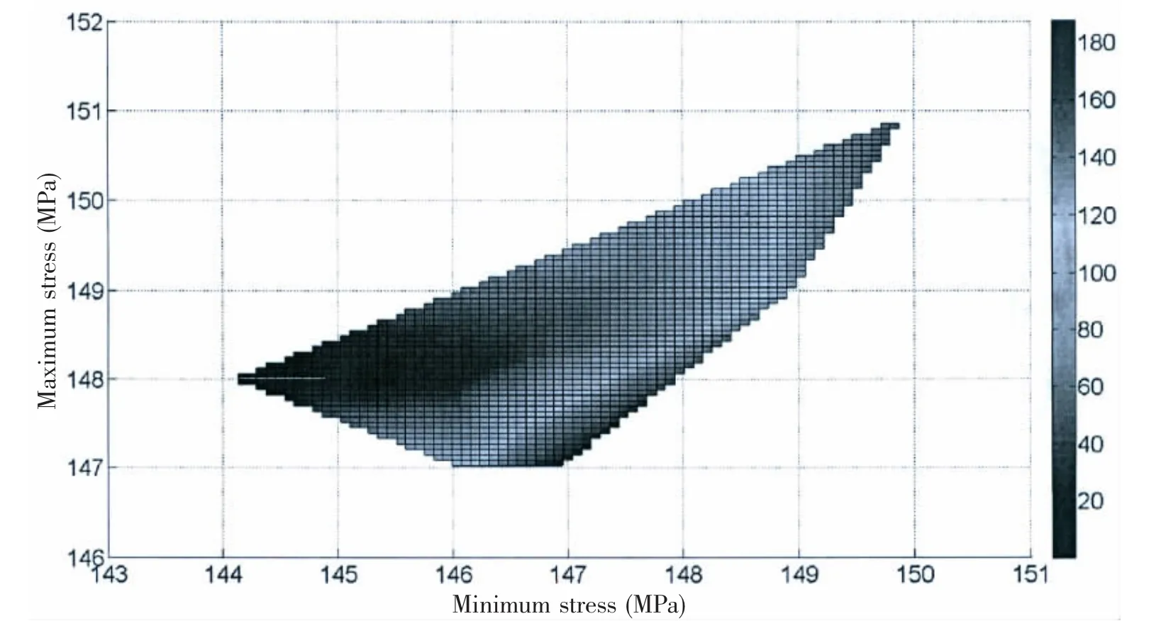
Fig.9 The calculated fatigue stress ranges and their cycles
As shown in Fig.8,the horizontal and vertical coordinates stand for minimum and maximum fatigue stress,respectively.The mean fatigue stress and fatigue stress range are the sum and the difference of the vertical and horizontal coordinates.The maximum fatigue stress under design load conditions is 151 MPa much smaller than the material yield stress,hence,theumbilical will not occur ultimate failure.As the stress is calculated based on the results in Fig.8,the data distribution in Fig.9 is almost the same as that in Fig.8.The maximum fatigue stress range is at(144,148)to be 4 MPa and the minimum fatigue stress range is at(146.7, 147)to be 0.3 MPa.The cycles of tension range decrease from 194 to 1with the increasing fatigue stress range.
The S-N curve is adopted in fatigue life prediction of the umbilical;and for the case in this paper,the following S-N curve is used according to Ref.[13].

To consider the mean stress level effects on the fatigue damages,the obtained stress ranges should be further corrected by Goodman line

where△σf,△σ,σutand σmare the equivalent fatigue stress range,the calculated fatigue stress range,the ultimate stress and the mean stress,respectively.
With the chosen S-N curve,the fatigue damage in one year of fatigue stress range i can be calculated by

where νidenotes fatigue damage of fatigue stress range σi,and nidenotes the cycles of fatigue stress range σiin one year and Nidenotes the cycles-to-failure of fatigue stress range σi.The corresponding results for the case in this paper are shown in Fig.10.

Fig.10 Fatigue damage of each stress range in one year
Fig.10 indicates that the largest fatigue damage is from the stress rang 1.5-2 MPa,whereas the 4-4.5 MPa stress range is the smallest part.Stress range between 1 to 3 MPa will serve as the primary contribution to the fatigue damage.Summing all of the fatigue damages induced by each stress range,the fatigue damage ν in one year can then be obtained as

According to Ref.[12],the fatigue damage produced by bending load is 2.67e-03.Comparing the fatigue damage of tension loads with that of bending loads,we can draw a conclusion that the tension load ranges hardly deduce fatigue damage to the umbilical and can be neglected in the fatigue analysis.
5 Conclusions
Taking the radial reduction of armor layer into consideration,the analytical model of tension stiffness is firstly deduced.And a very detailed FEM is developed to obtain the structural behavior under tension loads and to apply the value of radial reduction for the analytical model.To prove the validity of the analytical model and FEM,a prototype test result is presented. Based on the analytical model,a parameter study is conducted to investigate the effect of radial reduction on tension stiffness.Finally,the fatigue analysis of umbilical under deign tension load is carried out.Conclusions about umbilical tension behavior can be drawn as follows:
(1)The developed FEM can provide a good prediction of the tension behavior for the umbilical.
(2)The analytical model without the radial reduction overestimates the tension stiffness of the umbilical,the effect of the radial reduction on tension stiffness cannot be neglected.
(3)The radial reduction not only affects the value of the stiffness but also changes the distribution of the stiffness.
(4)The influence of radial reduction on the tension stiffness becomes less with smaller lay angle.
(5)The tension load ranges hardly deduce fatigue damage to the umbilical and can be neglected in the fatigue analysis.
[1]KNapp R H.Derivation of a new stiffness matrix for helically armored cables considering tension and torsion[J].International Journal for Numerical Methods in Engineering,1979,14:512-529.
[2]Feret J J,Bournazel C L.Calculation of stress and slip in structural layers of un-bonded flexible pipes[J].Journal of Offshore Mechanics and Arctic Engineering,1987,109:263-269.
[3]Ramos J R,Pesce C P.A consistent analytical model to predict the structural behavior of flexible risers subjected to combined loads[J].Journal of Offshore Mechanics and Arctic Engineering,2004,126:141-146.
[4]Ramos J R,Clovis A M,et al.A case study on the axial-torsional behavior of flexible riser[C].Proceedings of Offshore Mechanics and Arctic Engineering,2008.
[5]Witz J A,Tan Z.On the axial-tortional structural behavior of flexible pipes,umbilical and marine cables[J].Marine Structures,1992,5:205-227.
[6]Claydon P,Cook P,et al.A theoretical approach to perdition of service life of unbonded flexible pipes under dynamic loading conditions[J].Marine Structures,1992,5:399-429.
[7]Zhang W,Tuohy J.Application of finite element modeling in the qualification of large diameter unbonded flexible risers [C].Proceedings of Offshore Mechanics and Arctic Engineering,2002.
[8]Bahtui A,Bahai H,Alfano G.A finite element analysis for unbonded flexible risers under axial tension[C].Proceedings of Offshore Mechanics and Arctic Engineering,2008.
[9]Vaz M A,Rizzo N S A.A finite element model for flexible pipe armor wire instability[J].Marine Structures,2011,24: 275-291.
[10]Saevik S,Berge S.Correlation between theoretical predictions and testing of two-4-inch flexible pipes[C]//Energy-Sources Technology Conference and Exhibition.Houston,TX,ASME Petroleum Div.,PD,1993,51:63-78.
[11]CNOOC report.The fatigue analysis report of the unbonded umbilical[R].10,2012.
[12]DNV-RP-C203.Fatigue design of offshore steel structures[S].2010.
无粘接脐带缆轴对称响应与疲劳特性分析研究
郭有松1,陈希恰2,付世晓1,王德禹1
(1.上海交通大学海洋工程国家重点实验室,高新船舶与深海开发装备协同创新中心,上海200240;2.中海石油(中国)有限公司天津分公司渤海石油研究院,天津300452)
为了提高对脐带缆力学特性的研究,便于设计,文中提出了一种脐带缆拉伸载荷作用下的理论模型。在总体控制方程中对拉伸过程中骨架层的径向缩减。针对给定的无粘结脐带缆脐,建立了有限元模型,模拟分析了骨架层的径向缩减对应力分布的影响。通过对拉伸刚度试验对比,理论分析与试验吻合度较高。基于解析模型,分析了径向缩减对拉伸刚度的影响。此外,在应力分析的基础上,对无粘结脐带缆在拉伸载荷作用下的的疲劳特性进行了研究。
无粘结脐带缆;拉伸;刚度试验;径向缩减影响;数值模型;疲劳
O35
:A
国家自然科学基金资助(51239007)
郭有松(1974-),男,上海交通大学博士研究生;
O35
:A
10.3969/j.issn.1007-7294.2017.06.008
1007-7294(2017)06-0739-11
陈希恰(1988-),男,中海石油(中国)有限公司天津分公司渤海石油研究院工程师;
date:2016-12-06
Supported by the National Natural Science Foundation of China(51239007)
Biography:GUO You-song(1974-),male,Ph.D.candidate of Shanghai Jiao Tong University,E-mail: guoyousong@sjtu.edu.cn;CHEN Xi-qia(1988-),male,engineer of Tianjin Branch, CNOOC Ltd,E-mail:chenxq33@cnooc.com.cn.
付世晓(1976-),男,上海交通大学教授;
王德禹(1963-),男,上海交通大学教授,博士生导师。
猜你喜欢
电气自动化(2022年2期)2023-01-07 03:51:56
中学生数理化·高一版(2021年3期)2021-06-09 06:10:20
数学物理学报(2021年1期)2021-03-29 03:14:18
中国生殖健康(2020年2期)2021-01-18 02:51:32
重型机械(2020年3期)2020-08-24 08:31:40
健康博览(2019年10期)2019-12-02 04:48:51
数学年刊A辑(中文版)(2019年3期)2019-10-08 07:34:44
新世纪智能(英语备考)(2019年4期)2019-06-26 00:49:08
中国生殖健康(2018年2期)2018-11-06 07:10:54
家庭百事通·健康一点通(2016年9期)2016-09-21 02:31:35

- 船舶力学的其它文章
- Modified Backstepping Controller for Path Following of Marine Crafts with Actuator Dynamics
- Characteristic Study of the Random Wind Load on Semi-submersible Tender Support Platform
- Comparison on Different Schemes of Direct Numerical Simulation for Low/medium Reynolds Flow
- Sound Field Separation Technique Based on Acoustic Radiation Modes
- New Impulsive Factor in Representing Cabin Damage under External Air Explosion
- Numerical Simulation of Nonlinear Sloshing Waves in Three-dimensional Tank based on DBIEM