
Application of the dividing wall column to olefin separation influidization methanol to propylene(FMTP)process☆
2017-05-29 10:48:10XiaolongGeBotongLiuXigangYuanYiqingLuoKuoKsongYu
Xiaolong Ge ,Botong Liu ,Xigang Yuan ,*,Yiqing Luo ,Kuo-Ksong Yu
1 College of Chemical Engineering and Materials and Science,Tianjin Key Laboratory of Marine Resources and Chemistry,Tianjin University of Science and Technology,Tianjin 300457,China
2 State Key Laboratory of Chemical Engineering,Tianjin University,Tianjin 300354,China
1.Introduction
Distillation is extensively used in separating multi-component mixture.However,high energy consumption and capital cost make the practitioners strive to find effective solution to further promote its energy efficiency.Dividing wall column(DWC),also known as the fully thermally coupled distillation column(Petlyuk column)[1],which was firstly established in 1985,is regarded as the most practical technology for saving energy over the past three decades[2,3].
Initially,the DWC was used in final distillation,where the medium boiling component is the main component of interest.In this case the intermediate component usually needs to be separated from small amounts of light and heavy components.Currently,its application range has been largely expanded:hydrocarbons,alcohols,aromatics,ketones,aldehydes,amines,cryogenic air separation and C7+aromatics from olefin/paraffin[4–6].Obviously,there are no restrictions with respect to the type of chemicals.
Before investigating the operability of DWC,parameters including stage number in each column section,reflux ratio,side stream flowrate,liquid and vapor split ratio, flowrate of distillate should be specified.Various methods have been proposed for optimal design of DWC[7–10].With respect to control structure,three-point control structure with constant vapor and liquid split ratio was initially proposed by Wolf and Skogestad[11].Based on this criterion,various three-point control structures could be derived by pairing the controlled and manipulated variable differently.In 1999,Halvorson and Skogestad[12] firstly proposed the concept of employing liquid split ratio as manipulated variable,which was further developed by Ling and Luyben[13–15],Kiss and Rewagad[16].By employing liquid split ratio to control the prefractionator in directcomposition,temperature and temperature difference control structure,minimum energy requirement can be achieved.Besides conventional PID control structures,advanced control structures such as generic model control(GMC)[17,18]and model predictive control(MPC)[19]were proposed,which show shorter settling time for some cases.However,their practicability need to be further validated.Precious studies mainly concentrate on separating ternary mixture into three products with only one main component in each product[20].The energy saving performance for separating multi components into three products with more than one component in each product has not been extensively studied.Moreover,as for control structure design,contradict conclusion is usually derived because a fair comparison is impossible by employing differentseparation system.
In the presentwork,DWC was used to separate the feed mixture that is composed of 28 components into three products.Firstly,the energy consumption of DWC and conventional column sequence for olefin separation was compared,with each con figuration at their optimal operation conditions.Then a pilot DWC is designed in detail to determine the location of partition wall,the height of each column section and auxiliary internals.Finally,considering feed disturbance with four cases, five PID control schemes were proposed and their performance was compared.
2.Comparison Between the Performance of DWC and Conventional Columns
The conventional column sequence and DWC for separating ethylene-ethane-propylene in a process of fluidization methanol to propylene(FMTP)is shown in Fig.1.The FEED1 is vapor flow while the stream FEED2 is almost saturated liquid with liquid fraction 0.994.Mass balance and feed property for the designed DWC is displayed in Table 1.For simplification,the original 28 components mixture was regarded as feed mixture composed of seven main components.The mass fraction of the three products to total feed is 0.408:0.138:0.454 and the three products specification is shown in Table 2.As illustrated in Table 2,non-sharp split is conducted between ethylene and propene,while sharp split is conducted between propane and 1-butene.The annual production capacity of the pilot DWC with diameter 1.2 m/0.8 m is 217.8 thousand tons per year.
Before detailed design,the structural parameters and operating conditions of DWC need to be determined.There are seven structural variables and five operating variables needed to be optimized,including stage number in seven column sections,distillate flowrate,side stream flowrate,reflux ratio,vapor and liquid split ratio.This turned to be a mixed integer nonlinear programming problem(MINLP),which could be effectively solved by combining simulation software with stochastic algorithm such as genetic algorithm,which has been reported by our research before[10].With respect to detailed design,the flow resistance in the two sides of dividing wall was checked rigorously to ensure vapor and liquid split ratio at their optimal design value.
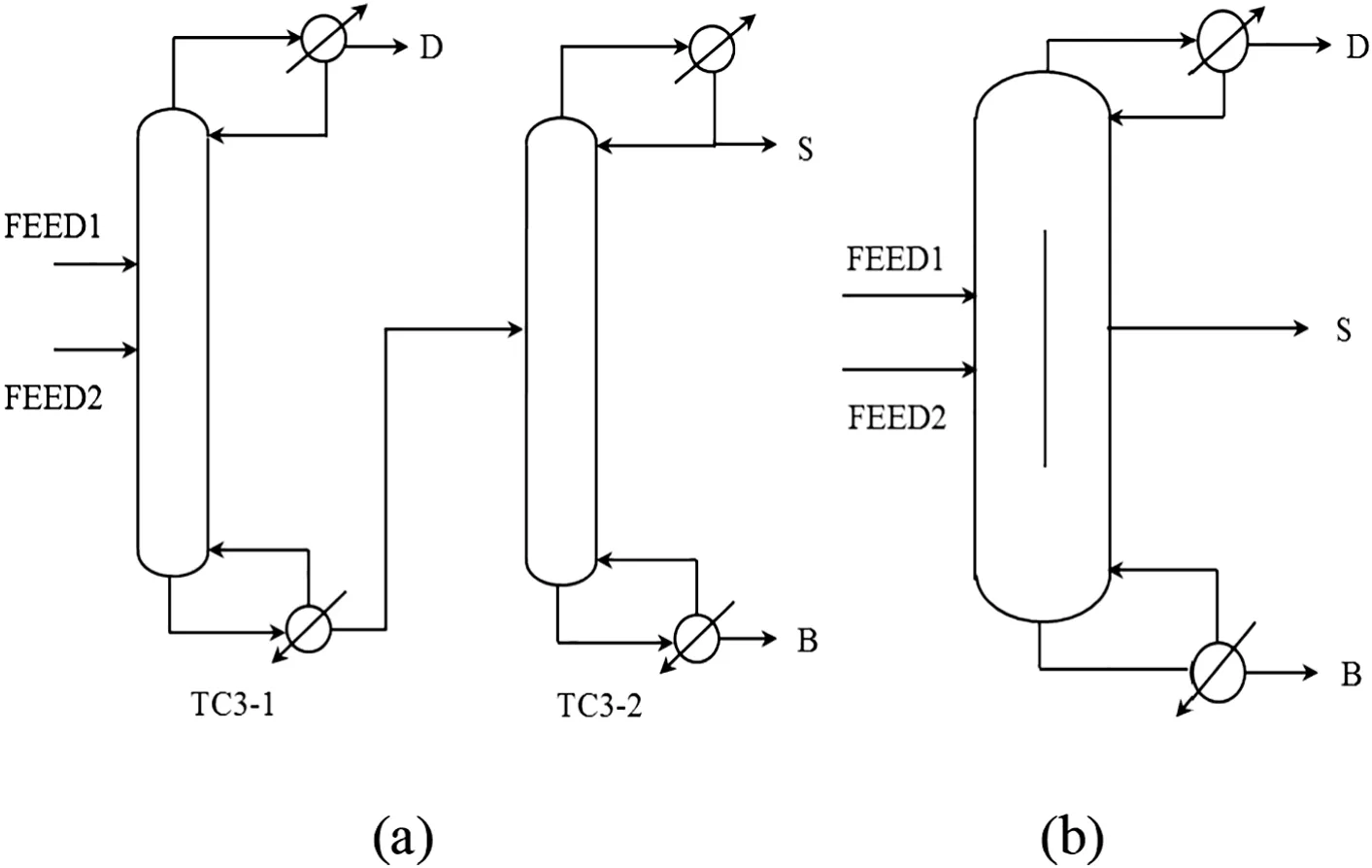
Fig.1.Flowsheet for separating olefin mixture in a process of fluidization methanol to propylene(FMTP):(a)conventional column sequence(b)DWC.

Table 1Mass balance and property for the designed pilot dividing wall column
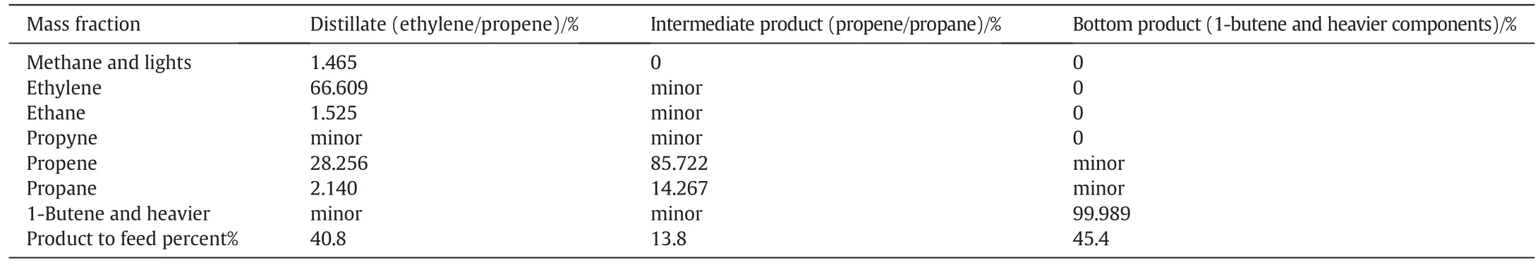
Table 2Three products specification
Compared to the direct column sequence for separating this mixture,DWC can save hotand cold utility by 30.2%and 25.7%,respectively,which is shown in Table 3.The cold utility forthe designed pilotdividing wallcolumn is refrigeration(-20°C)and the hot utility is low pressure steam(160 °C,0.5 MPa).The moderately lowrefrigeration system(5 °C)cannot be used for cooling because all of the condensers'temperature is below this value.Increasing the pressure can make the column use Refrigerated Water(15 °C to 25 °C)and Cooling Water(30 °C to 45 °C),however,energy demand would increase dramatically[21].
The reason why the DWC can save energy is that“remixing effect”existed in the conventional column sequence could be eliminated in DWC.The composition pro files of propene in the first column of the conventional column sequence and prefractionator of DWC are displayed in Fig.2.The composition of propene increases toward the bottom of the prefractionator in DWC.However,in the conventional column sequence,the composition of propene first increases toward to the bottom of the column,if we move further down to the bottom,the composition starts to decrease,which refers to “remixing effect”.

Table 3Comparison between dividing wall column(DWC)and conventional distillation column
3.Detailed Design of the Pilot Dividing Wall Column
The energy saving performance of DWC consists in using an optimal vapor split ratio,which was significantly influenced by the partition wall location in the column shell and flow resistance in the two sides of partition wall[22,23].The partition wall's location in the shell can be determined by precisely balancing the pressure drop in two sides of dividing wall.
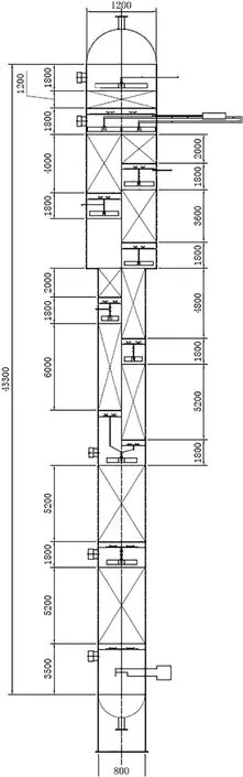
Fig.3.Detailed drawing of the pilot dividing wall column.

Fig.2.Composition pro file of propene:(a)the first column of the conventional column sequence(b)prefractionator of DWC.
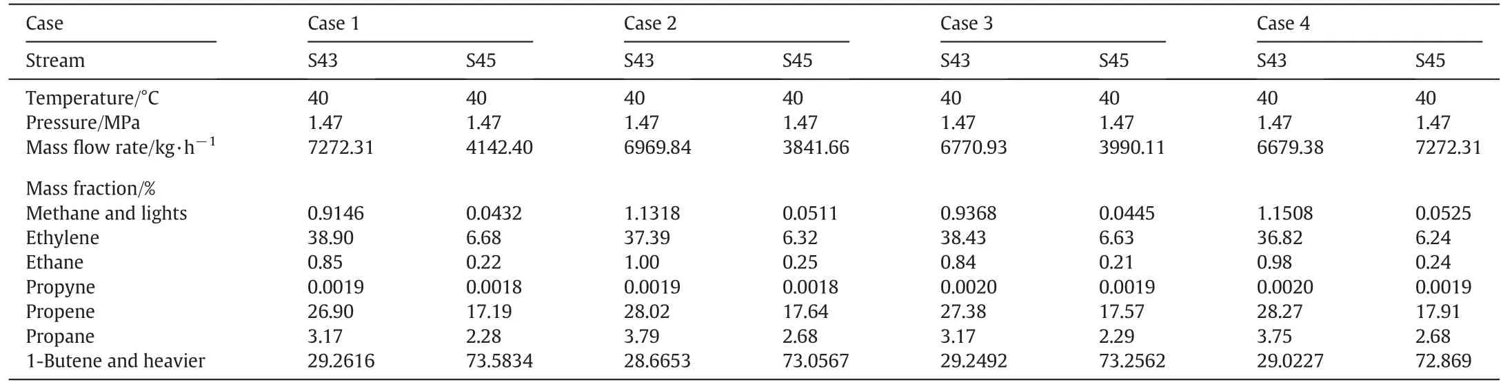
Table 4Four cases for feed condition
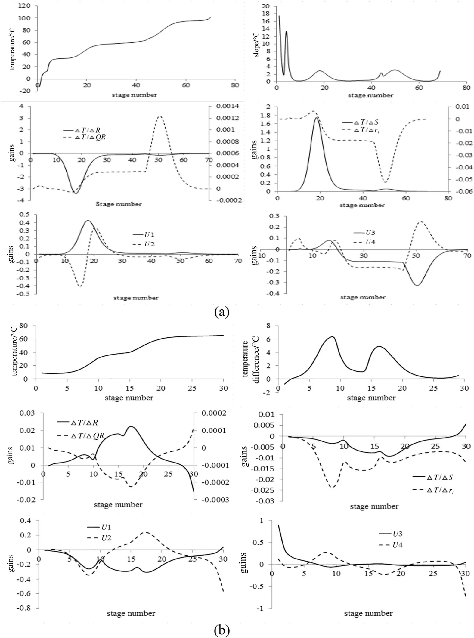
Fig.4.Sensitivity and singular value decomposition analysis for(a)main column(b)prefractionator.
Due to the vapor phase of FEED1,the vapor load of the column section above FEED1 is significantdifferent from the column section below FEED1.If uniform column diameter is used,operating difficulty such as weeping and flooding in some column sections may occur.Therefore,column sections with different diameters are used to design the pilot DWC.The diameter of the column section above FEED1 is 1.2 m while the diameter below FEED1 is 0.8 m.
The procedure for determining the location of partition wall was as followed: firstly the vapor split ratio is fixed at optimal value.Then by changing the location of partition wall,the vapor velocity in the two sides of dividing wall would change,thus the pressure drop can be calculated.This pressure rating procedure is an iteration process,which terminates until the pressure drop in the two sides of dividing wall becomes the same.For packed column,the pressure drop of the collector and liquid distributor,packing can be determined easily by correlations which can be found in the literature and book[24].
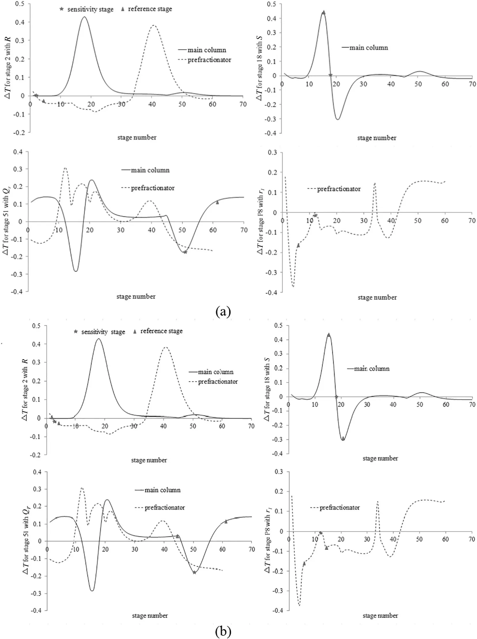
Fig.5.SVD analyses for selecting differential temperature stage for(a)temperature difference control structure(TDC)(b)double temperature difference control structure(DTDC).
For rigorous simulation,the diameterofeach column section was set in “Tray Rating”module in the simulation software,e.g.the diameter of common rectifying section was set as 1.2 m and that of common stripping column section set as 0.8 m.For the prefractionator,the column section above FEED1 was determined as 0.849 m and that below FEED1 was 0.566 m,which means the partition wall set at the center of the column.For this DWC,the stage number in the two sides ofpartition wallis different.There are 30 stages in the prefractionator and 39 stages in the side stream column section.Similar to prefractionator,the side stream column section was divided into two parts according to its corresponding stage number proportion with prefractionator.The diameter of upper part was determined as 0.849 m while that of lower part was determined as 0.566 m.
By hydraulic rating,each column section could operate at appropriate flooding factor with dividing wall set at the center of the column.The pressure drops in the two sides of partition wall are 12.62 kPa and 11.486 kPa,respectively,which ensures vapor split ratio at optimal design value.
The detailed drawing for the designed pilot dividing wall column is shown in Fig.3,including the associated packed beds and all auxiliary devices,i.e.liquid collectors and distributors,an external liquid splitter,and packing support grids.The liquid distributors are narrow through type with drip tubes and liquid collectors are determined as chevron type.The criterion for selecting column internals type could be found in literature[25–27].


Fig.6(continued).
4.Control Structure Design
The olefin mixture is the ef fluent of fluidized bed,which results in feed flow rate and composition change.There are four cases for feed disturbance,which are shown in Table 4.
In orderto circumventfeed disturbance, five control structures were proposed,i.e.,direct composition control(CC),temperature control(TC),composition-temperature cascade control(CC-TC),temperature difference control(TDC),double temperature difference control(DTDC).As for TC,TDC and DTDC,sensitivity criterion and singular value decomposition(SVD)criterion was used to determine the controlled stage location[28–30].To implement sensitivity analysis,a small change was made to the manipulated variable(R,QR,Sandrl),the change in each temperature tray divided by the change of manipulated variable gives the steady gain for that tray.The main column matrix has 70 rows and 4 columns while prefractionator matrix has 30 rows and 4 columns.Each matrix was decomposed by SVD function in Matlab software into three matrices:K=U∑VT.The four U vectors are plotted against stage number.The result of sensitivity analysis and SVD analysis for main column and prefractionator was shown in Fig.3,from which temperature controlled trays were selected[31].In CC-TC,the controlled temperature stage is the same with that in TC.
In order to achieve product specification and minimize energy consumption simultaneously,the temperature set point should change as the feed disturbance occurs.However,the controlled temperature is set constant in TC.To handle this problem,DTC and DTDC were proposed because adjacent stage shows similar temperature change as the feed disturbance occurs.In this way,keeping the temperature difference between adjacent trays constant would not result in maximum deviation from original product specification.
As for TDC,each loop has two stage temperatures.One is determined as the same with stage in TC,which was termed as sensitivity stage.As shown in above-mentioned TC,the four controlled stages are 2,18,and 51 in the main column and stage 8 in the prefractionator,respectively.The steady gain between the four temperatures and four manipulated variables are determined.For example,the four gains areK2,ΔT/ΔR,K2,ΔT/ΔQR,K2,ΔT/ΔS,K2,ΔT/Δrlfor stage 2.The gains for other stages could also be obtained and the gain of stagenwas termed asKn,ΔT/ΔR,Kn,ΔT/ΔQR,Kn,ΔT/ΔS,Kn,ΔT/Δrl.Then the difference between the gains for stage 2 and stagenare calculated,which generates the matrix of gain difference ΔK2,this matrix has 70 rows and 4 columns.SVD analysis gives U1vector which was plotted against stage number.The result was shown in Fig.4.The stage has the largest ΔU1with sensitivity stage was selected as reference stage.However,it should be notedthatthis criterion is notalways effective in selecting differentialtemperature control stage.For example,as shown in Fig.5(a),the reference temperature is selected as stage 4 because itlocates in the same column section with stage 2 and gives better performance than selecting stage 18 which indicates the largest ΔU1.

Table 5Controller tuning parameters for five control structures
The procedure for selecting two reference temperatures for DTDC is similar with TDC.The result is shown in Fig.5(b).
Fig.6 shows thefive controlframes with main regulatory controllers.All of the five control structures are implemented in Aspen Dynamic using conventional PID controllers.

Fig.7.Comparison of the performance of five control structures for feed disturbance case 2.
The inventory controllers include level controllers,pressure controllers and flow controllers.The gain of all level controllers is 2.The gain and integral time for all pressure controllers isKC=20 and τC=12min.For flow controllers,KC=0.5 and τC=0.3min is used.
The four regulatory controllers were tuned using a sequential method.TheQRloop is tuned first with other three controllers on manual mode.Relay-feedback test was run and Tyreus-Luyben rules were used to calculate the ultimate gains and integral time.ThenRloop was tuned withQRloop set automatic.ThenSloop was tuned withQRandRloops on automatic mode.Finally,rlloop was tuned with the other three loops on automatic mode.The tuning results are shown in Table 5.
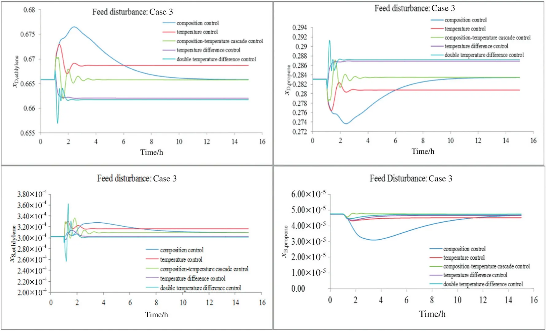
Fig.8.Comparison of the performance of five control structures for feed disturbance case 3.
Figs.7 to 9 give the control structure performance of the proposed five control structures,subject to feed disturbance in Cases 2,3,and 4 shown in Table 4.For all cases,the maximum deviation and settling time is large for CC,which takes 10 h to reach the new steady state.This could be significantly reduced by employing tighter control structure-TC.TDC and TC show similar performance and are superior to DTDC in terms of divergence number.

Fig.9.Comparison of the performance of five control structures for feed disturbance.
5.Conclusions
A pilot dividing wall column with diameter of 1.2 m/0.8 m is designed in detail for olefin separation,which shows 30%energy saving compared to the present conventional distillation sequence.The observation of the “remixing effect”of the intermediate component in the deethanizer column demonstrates the inefficiency in conventional column,which can be eliminated by DWC.The result demonstrates that DWC is also could be employed to separate mixture with low fraction of intermediate product.Moreover,for this specific feed conditions(with one vapor feed),column sections with different diameters are appropriate for operating the pilot DWC.
Maintaining vapor split ratio at optimal value is the key point to successfully design a DWC.Optimal vapor split ratio could be obtained by optimizing operating parameters firstly,and ensured by appropriately arranging the flow resistance in the two sides of partition wall.As shown and demonstrated in this olefin separation case,this could be done by using the published mathematical correlations for estimating the pressure drop of packings and its associated device,e.g.liquid distributor and collector,respectively.
To circumvent feed disturbance in operation, five control structures were proposed.Sensitivity analysis and singular value decomposition(SVD)was shown to be effective for selecting the sensitive and reference temperature location.Among the five control schemes,temperature control(TC)and temperature difference control(TDC)shows superior performance,i.e.with lower maximum deviation and shorter settling time.
Nomenclature
K gain matrix
KCcontroller ultimate gain
ΔK matrix of gain difference
QRreboiler duty,kW
RReflux rate,kg·h-1
rlliquid split ratio
S side stream mass flow rate,kg·h-1
xD,propenepropene mass fraction in distillate
xS,butene1-butene mass fraction in side stream
xW,propenepropene mass fraction in bottom product
yP,butene1-butene mass fraction in the vapor stream leaving the prefractionator top
τCcontroller integral time,min
[1]F.B.Petlyuk,V.P.,D.M.Slavinski,Thermodynamically optimal method for separating multicomponent mixtures,Int.Chem.Eng.5(3)(1965)555–561.
[2] Ž.Olujić,M.Jödecke,A.Shilkin,G.Schuch,B.Kaibel,Equipmentimprovementtrends in distillation,Chem.Eng.Process.48(6)(2009)1089–1104.
[3]M.A.Schultz,D.G.Stewart,J.M.Harris,S.P.Rosenblum,M.S.Shakur,D.E.O'Brien,Reduce costs with dividing-wall columns,Chem.Eng.Prog.98(5)(2002)64–71.
[4]Ö.Yildirim,A.A.Kiss,E.Y.Kenig,Dividing wallcolumns in chemical process industry:A review on current activities,Sep.Purif.Technol.80(3)(2011)403–417.
[5]N.Asprion,G.Kaibel,Dividing wall columns:Fundamentals and recent advances,Chem.Eng.Process.49(2)(2010)139–146.
[6]I.Dejanović,L.Matijašević,Ž.Olujić,Dividing wall column—A breakthrough towards sustainable distilling,Chem.Eng.Process.49(6)(2010)559–580.
[7]C.Triantafyllou,R.Smith,The design and optimisation of fully thermally coupled distillation columns,Chem.Eng.Res.Des.70(A2)(1992)118–132.
[8]C.Gutiérrez-Antonio,A.Briones-Ramírez,Pareto front of ideal Petlyuk sequences using a multiobjective genetic algorithm with constraints,Comput.Chem.Eng.33(2)(2009)454–464.
[9]J.A.Vazquez-Castillo,J.A.Venegas-Sánchez,J.G.Segovia-Hernández,H.Hernández-Escoto,S.Hernández,C.Gutiérrez-Antonio,A.Briones-Ramírez,Design and optimization,using genetic algorithms,of intensified distillation systems for a class of quaternary mixtures,Comput.Chem.Eng.33(11)(2009)1841–1850.
[10]X.Ge,X.Yuan,C.Ao,K.-K.Yu,Simulation based approach to optimal design of dividing wall column using random search method,Comput.Chem.Eng.68(0)(2014)38–46.
[11]E.A.Wolff,S.Skogestad,Operation of integrated three-product(Petlyuk)distillation columns,Ind.Eng.Chem.Res.34(6)(1995)2094–2103.
[12]I.J.Halvorsen,S.Skogestad,Optimal operation of Petlyuk distillation:Steady-state behavior,J.Process Control9(5)(1999)407–424.
[13]H.Ling,W.L.Luyben,New control structure for divided-wall columns,Ind.Eng.Chem.Res.48(13)(2009)6034–6049.
[14]H.Ling,W.L.Luyben,Temperature control of the BTX divided-wall column,Ind.Eng.Chem.Res.49(1)(2009)189–203.
[15]H.Ling,Z.Cai,H.Wu,J.Wang,B.Shen,Remixing control for divided-wall columns,Ind.Eng.Chem.Res.50(22)(2011)12694–12705.
[16]A.A.Kiss,R.R.Rewagad,Energy efficient control of a BTX dividing-wall column,Comput.Chem.Eng.35(12)(2011)2896–2904.
[17]R.C.van Diggelen,A.A.Kiss,A.W.Heemink,Comparison of control strategies for dividing-wall columns,Ind.Eng.Chem.Res.49(1)(2009)288–307.
[18]A.A.Kiss,C.S.Bildea,A control perspective on process intensification in dividingwall columns,Chem.Eng.Process.50(3)(2011)281–292.
[19]S.-J.Wang,D.S.H.Wong,Controllability and energy efficiency ofa high-purity divided wall column,Chem.Eng.Sci.62(4)(2007)1010–1025.
[20]G.Niggemann,C.Hiller,G.Fieg,Experimental and theoretical studies of a dividingwall column used for the recovery of high-purity products,Ind.Eng.Chem.Res.49(14)(2010)6566–6577.
[21]R.Turton,R.C.Bailie,W.B.Whiting,J.A.Shaeiwitz,Analysis,Synthesis and Design of Chemical Processes,Prentice Hall,New York,2008.
[22]D.Dwivedi,J.P.Strandberg,I.J.Halvorsen,H.A.Preisig,S.Skogestad,Active vapor split control for dividing-wall columns,Ind.Eng.Chem.Res.51(46)(2012)15176–15183.
[23]X.Ge,C.Ao,X.Yuan,Y.Luo,Investigation of the effect of the vapor split ratio decision in design on operability for DWC by numerical simulation,Ind.Eng.Chem.Res.53(34)(2014)13383–13390.
[24]I.Dejanović,L.Matijašević,H.Jansen,Z.A.Olujić,Designing a packed dividing wall column for an aromatics processing plant,Ind.Eng.Chem.Res.50(9)(2011)5680–5692.
[25] Ž.Olujić,I.Dejanović,B.Kaibel,H.Jansen,Dimensioning multipartition dividing wall columns,Chem.Eng.Technol.35(8)(2012)1392–1404.
[26]I.Dejanović,L.Matijašević,I.J.Halvorsen,S.Skogestad,H.Jansen,B.Kaibel,Ž.Olujić,Designing four-product dividing wall columns for separation of a multicomponent aromatics mixture,Chem.Eng.Res.Des.89(8)(2011)1155–1167.
[27]I.Dejanović,I.J.Halvorsen,S.Skogestad,H.Jansen,Ž.Olujić,Hydraulic design,technical challenges and comparison of alternative con figurations of a four-product dividing wall column,Chem.Eng.Process.84(0)(2014)71–81.
[28]S.Luan,K.Huang,N.Wu,Operation of dividing-wall columns.1.A simplified temperature difference control scheme,Ind.Eng.Chem.Res.52(7)(2013)2642–2660.
[29]C.-C.Lin,T.-J.Ho,W.-T.Liu,Distillation in a rotating packed bed,J.Chem.Eng.Jpn35(12)(2002)1298–1304.
[30]Y.Yuan,K.Huang,Operation of dividing-wall distillation columns.3.A simplified double temperature difference control scheme,Ind.Eng.Chem.Res.53(41)(2014)15969–15979.
[31]W.L.Luyben,Distillation Design and Control Using Aspen Simulation,Wiley&Sons,USA,2013.
 Chinese Journal of Chemical Engineering2017年8期
- Chinese Journal of Chemical Engineering的其它文章
- Step-wise synthesis of work exchange networks involving heat integration based on the transshipment model☆
- The mass and heat transfer process through the door seal of refrigeration☆
- Performance of CO2 absorption in a diameter-varying spray tower☆
- Optimal design of heat exchanger header for coal gasification in supercritical water through CFD simulations☆
- Coupled simulation of recirculation zonal firebox model and detailed kinetic reactor model in an industrial ethylene cracking furnace☆
- Optimization and control of a reactive distillation process for the synthesis of dimethyl carbonate☆