Design and Implementation of a TDD-Based 128-Antenna Massive MIMO Prototype System
Xi Yang, Wenjun Lu, Ning Wang, Karl Nieman, Chao-Kai Wen, Chuan Zhang, Shi Jin,*,Xiaomin Mu, Ian Wong, Yongming Huang, Xiaohu You
1 National Mobile Communications Research Laboratory, Southeast University, Nanjing 210096, China
2 Jiangsu Key Laboratory of Wireless Communications, Nanjing University of Posts and Telecommunications, Nanjing 210003, China
3 School of Information Engineering, Zhengzhou University, Zhengzhou 450001, China
4 National Instruments, Austin 78759, Texas, USA
5 Institute of Communications Engineering, National Sun Yat-sen University, Kaohsiung 804, Taiwan, China
I. INTRODUCTION
The fifth-generation (5G) cellular system,which is expected to be released in 2020 according to the IMT-2020 road map [1], represents a paradigm shift in mobile networking.To achieve the visions of 5G, simple evolutions from existing wireless technologies, such as 3GPP LTE and Wi-fiare insufficient. New disruptive technologies must be introduced to both network and device levels. Among these technologies, massive multiple-input multiple-output (MIMO) is considered the most significant breakthrough in base stations (BSs)[2]. Different from the conventional multi-user MIMO (MU-MIMO), massive MIMO promises significant gains in wireless data rates and link reliability by using a large excess of BS antennas to serve a relatively small number of user equipment (UE) over the same time-frequency resource block. Massive MIMO has elicited increasing attention from the academe and industries in recent years and has become one of the most dynamic research topics in wireless communications [3]–[14].
Reference [3] showed that in a massive MIMO system, the MU-MIMO channel is asymptotically orthogonal when the channel coefficients for different antenna elements are independent and identically distributed (i.i.d.).Therefore, by fully exploiting the spatial degrees of freedom of the large-scale antenna array, hardware-friendly linear precoding schemes, such as maximal-ratio transmitting(MRT) and zero forcing (ZF), are sufficient to achieve optimal performance. In addition, Ngo et al. [15] reported that massive MIMO presents promising potentials to improve energy efficiency, which is significantly important for future green wireless networks.
Although massive MIMO technology has many desirable features that could be used in future wireless networking, the use of a largescale antenna array raises new issues. First,obtaining accurate instantaneous channel state information on the transmitter side is difficult for the downlink, especially when the system operates in the frequency division duplex(FDD) mode [5]. Even in the time division duplex (TDD) mode, hardware mismatch exists between BS and UE, and this mismatch impairs channel reciprocity and necessitates radio frequency (RF) calibration before downlink transmission [6], [16]–[18]. Second, hardware and computational complexity increase dramatically with the size of large-scale antenna arrays; this increase poses challenges to the design and implementation of massive MIMO prototype systems. These challenges include(1) large demand for flexible software-defined radios (SDRs) to receive and transmit RF signals, (2) precise time and frequency synchronization among different RF devices, (3) high throughput data bus to collect and transfer massive data, and (4) high computation capability and processing power required by the real-time signal processing in the execution of physical layer (PHY) functionalities.
Building a massive MIMO prototype system is essential as its potential and feasibility must be verified before commercial deployment. Several basic prototypes have been developed for massive MIMO, and these include Argos [21]–[23] developed by Rice University, Lund massive MIMO (LuMaMi) [24], [25]created by Lund University in collaboration with Bristol University, open air interface(OAI) 64-antenna massive MIMO testbed [26]designed by Eurocom, and ARIES implemented by Facebook [27]. By using hierarchical and modular design principles, Argos demonstrates scalability and flexibility when implemented. Argos V1 [21] was built with a 64-antenna BS and serves 15 single-antenna users simultaneously with 0.625 MHz of bandwidth in the TDD mode. Channel measurements are conducted for line-of-sight (LOS) and nonline-of-sight (NLOS) scenarios by measuring signal to interference plus noise ratio. In Argos V2 [22], an upgraded version of Argos V1,the number of BS antennas is increased to 96,and 32 data streams are supported. Both Argos V1 and V2 were built based on commercially available hardware, namely, Wireless Open Access Research Platform, which has an open field programmable gate array (FPGA) and two RF chains on board. Compared with Argos, LuMaMi is a 100-antenna SDR-based centralized massive MIMO testbed capable of serving 12 single-antenna users in the same time-frequency resource with a TDD LTE-like frame structure over 20 MHz of bandwidth.On the contrary, the OAI massive MIMO testbed is a general purpose processor (GPP)-based 64-antenna LTE-compliant massive MIMO prototype system; it can serve up to four user equipments simultaneously with 5 MHz of bandwidth. In addition, Facebook developed a 96-antenna massive MIMO prototype system capable of supporting 24 data streams in their ARIES project. Several leading communication network equipment manufacturers, such as Huawei, ZTE, and Samsung,have also involved in massive MIMO-related research and development activities.
Most of the existing work on prototype massive MIMO focus on either channel measurement or complex system design from the hardware point of view. A clear, detailed system design procedure starting from theory to link-level simulation and until system hardware design is lacking. Clearly clarifying the link-level process of a TDD-based massive MIMO prototype system would help researchers solve practical problems and propose optimal algorithms. To address these limitations,we present the design and implementation of a TDD-based 128-antenna massive MIMO prototype system from theory to reality. To provide an overview of the fundamentals behind the proposed prototype system design, we first present the analytical model of the TDD-based massive MIMO system. Second, the detailed procedure of link-level simulation (including uplink and downlink transmission processes),which is consistent with a practical prototype system, is described. The purpose of the link-level simulation is to verify the feasibility of the entire transmission scheme and provide guidance to system debugging and algorithm selection. Finally, we present the system setup and experiment results to validate our system design.
The main contributions of this work are summarized as follows:
(a) We provide an analytical signal model for a practical TDD-based massive MIMO prototype system. The designs of the frame structure, frequency orthogonal pilot, and QR decomposition-based linear minimum mean square error (LMMSE) detector are included. The analytical signal model facilitates the setup of a feasible massive MIMO prototype system.
(b) The entire procedure of the link-level simulation, which is consistent with a practical TDD-based 128-antenna massive MIMO prototype system, is presented. Given that the hardware mismatch between BS and UE is considered, the emulation of the link-level processing procedure for the prototyping system is valuable when evaluating the processing algorithms implemented (e.g., RF calibration algorithm and multi-user precoding).
(c) We design and build a practical TDD-based 128-antenna massive MIMO prototype system. The frame structure of the prototyping system is reconfigured, and real-time video transmission in the uplink and constellation data transmission in the downlink are achieved. The successful real-time high-definition (HD) video transmission of multiple single-antenna users highlights the low-processing latency and better bit error rate (BER) performance of our system. Additionally, we study the measurements of multi-user massive MIMO channels over 20 MHz of bandwidth and the impact of reciprocity calibration.
The rest of this paper is organized as follows. The theoretical system model is presented in Section II. Section III describes the system link-level simulation in detail. The system design and experiment setup for validating the prototype design are presented in Section IV, and Section V presents the corresponding experimental results and comparisons with state-of-the-art prototyping systems. The conclusions are provided in Section VI.
Notation: We use uppercase and lowercase boldface letters to denote matrices and vectors, respectively. The N×N identity matrix is denoted by IN, the all-zero matrix is denoted by 0, and the all-one matrix is denoted by 1. ek∈ℝK×1represents the kth unit vector,i.e., the vector that is zero in all entries, except for the kth entry in which it is set to 1.The superscripts (⋅)H, (⋅)T, and (⋅)*stand for conjugate-transpose, transpose, and conjugate operations, respectively.
II. SYSTEM MODEL
The signal model for our TDD-based massive MIMO prototype system is presented in this section. The analytical model offers an over-view of the fundamentals behind the proposed prototyping system design and facilitates the setup of a feasible massive MIMO prototype system.
2.1 Scenario
We consider a single-cell multi-user (MU)massive MIMO system, in which the BS is equipped with M antennas and simultaneously serves K (K≪M) single-antenna users at the same time-frequency resource (figure 1). The system operates in TDD mode, and orthogonal frequency division multiplexing (OFDM) technology is utilized. Figure 2 shows the LTE-like frame structure1To reduce realization complexity, we adopt a simplified version of 3GPP TDD-LTE frame structure, where sounding reference signal(SRS) and demodulation reference signal (DMRS) are replaced by user pilots, and the usage of OFDM symbols in frame structure is unique,i.e., the OFDM symbol is dedicated to either transmitting pilots or transmitting user data.. Specifically, a 10 ms radio frame is divided into 10 subframes. Except for Subframe 0, which is used for synchronization between BS and UE through the primary synchronization signal (PSS), all the other subframes (i.e. Subframes 1 to 9) are used for data transmission. Each subframe has the same structure of two 0.5 ms time slots, and each time slot consists of seven OFDM symbols.Given that the frame schedule in our prototyping system is software programmable, the frame structure can be reconfigured flexibly to meet the data transmission demand in different scenarios. Additionally, we can allocate all the data OFDM symbols to either uplink or downlink transmission to achieve the highest data transmission rate and spectral efficiency.Notably, the guard OFDM symbol is reserved for the TDD switch. No data are transmitted in the guard OFDM symbol. In this example,we arrange two OFDM data symbols for the uplink because of the uplink real-time video streaming application to be realized in our prototyping system.
2.2 Uplink data transmission
Before the uplink data transmission, the uplink pilot OFDM symbol is transmitted by K single-antenna users (labeled asfor channel estimation at the BS. We adopt frequency orthogonal pilots for different users,and the K neighboring subcarriers are successively allocated to K users, e.g., subcarrier i is used for, then subcarrier K is again used for UE0, and so on. Details on the resource allocation scheme are provided in figure 3. As shown in figure 3, we group every K consecutive subcarriers into a subband2Under current settings,K=12, so each sub-band consists of 12 consecutive subcarriers., which provides N/K sub-bands marked as Sub0, Sub1, ..., Sub N/K−1. Each user only transmits pilots on its allocated subcarriers of each sub-band on the pilot OFDM symbol; the other K−1 subcarriers on the sub-bands are preserved. Once the channel is estimated forby the pilot on subcarrierin Sub i through the method of least square (LS), the channel estimate is used for the other K−1 subcarriers in Sub i, i.e., zero-hold is utilized in each subband in our system. The signal model of the uplink pilot transmission at Sub i over the block fading channel is given by

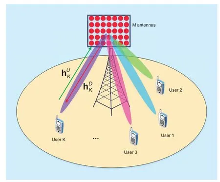
Fig. 1 Single-cell MU massive MIMO system. BS is equipped with M antennas and simultaneously serves K (K≪M) randomly distributed single-antenna users at the same time-frequency resource
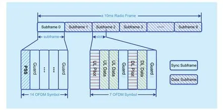
Fig. 2 Frame structure. A 10 ms radio frame is divided into 10 subframes. Subframe 0 is used for synchronization between the BS and UEs. Subframes 1 to 9 are used for data transmission, where each subframe is composed of two 0.5 ms slots, and each slot consists of seven OFDM symbols: Uplink (UL) Pilot, UL Data,UL Data, Guard, Downlink (DL) Pilot, DL Data, and Guard

Fig. 3 Time-frequency resource grids of twelve single-antenna UEs. Frequency orthogonal pilots are employed for the twelve single-antenna UEs and the number of subcarriers in one subband is 12

Substituting (1) into (2) results in

After the uplink pilot OFDM symbol,uplink data OFDM symbols are transmitted by K users over the same time-frequency resource blocks. We assume thatis the transmitted vector with snkfor k=1,…,K being the i.i.d.zero-mean unit-variance transmitted complex message from UEk. The received signal at the BS is provided by


where

As can be observed from (6), matrix inversion must be implemented to achieve the LMMSE detector. This inversion results in significant computational complexity especially in FPGA-based massive MIMO prototyping systems. To address this challenge, we use the QR decomposition approach as discussed in[20], [28], [29] to solve the matrix inversion problem. We define the extended channel matrix as

where QR decomposition is introduced in the second equation and (M+K)×K matrix Q with orthonormal columns is partitioned into M×K matrix Q1and K×K matrix Q2, R is a K×K upper triangle matrix. By substituting (7) into (6), Wlmmse,ncan be derived as

From (7), we can see

and

which means

Combining (8), (9), and (11) results in

Hence, matrix inversion can be replaced with the QR decomposition of the extended channel matrix B, which can be easily realized through Gram-Schmidt orthogonalization.
2.3 Downlink data transmission
Similar to that in the uplink, the BS in the downlink transmits the pilot OFDM symbol,followed by the downlink data OFDM symbols. The allocation of the downlink pilot is similar to that in the uplink, and frequency orthogonal pilots are used for different users.In addition, consistent with the transmission of downlink data, downlink pilots are also subjected to downlink precoding, which means the channel estimates on the user equipment sides are effective channels. We let xn∈ℂK×1denote the information-bearing signals to be transmitted to K single-antenna users. It satisfies the power constraint, i.e.,,where ρ is the total transmitting power at BS.We use Fn∈ℂM×Kfor the precoder matrix and the received signal at K users is given by

In our massive MIMO prototyping system,two precoding strategies, namely, LMMSE precoding and MRT precoding, are employed.For LMMSE precoding, precoder matrix Fnis given by

and for MRT, precoder matrix Fnis defined as

where diagonal matrix Λ1nand Λ2nare introduced to normalize the columns ofand, respectively.
On the user side, least square channel estimation and maximal-ratio combining are employed. Given the use of frequency orthogonal pilots and supposing that nmodK=k , the downlink pilot vector on subcarrier n before precoding at the BS is given bywhere pnkis a QPSK modulated symbol with a unit norm for user k on subcarrier n. We defineand, whereis the column vector of the effective precoder matrix, andis the downlink channel of user k on subcarrier n. The estimate of the effective channel onsubcarrier n for user k is given by
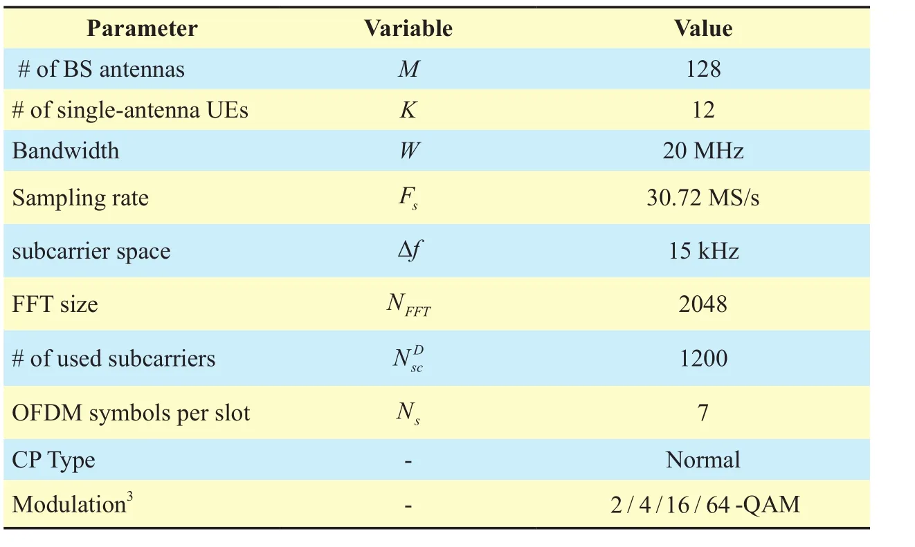
Table I System simulation parameters

where the second item is the downlink channel estimate error. Subsequently, the single-antenna user processes its received data by multiplying the conjugate-transpose of the effective channel estimate, which, according to (13),results in

By combining (16) and (17), we obtain


III. LINK-LEVEL SIMULATION
A link-level simulation of the TDD-based 128-antenna massive MIMO system is presented in this section. First, we present the simulation parameters including system configuration and channel model. Second, we show the system block diagram that illustrates the link-level transmission procedure in detail.Numerical results are presented at the end of the section.
3.1 Simulation parameters
The simulation is conducted similar to that for LTE cellular systems. The settings of the simulation parameters are shown in Table 1. Both OFDM technology and frequency orthogonal pilots are employed in the link-level simulation. The time-frequency resource grids of the 12 single-antenna users are presented in figure 3, where each sub-band contains 12 subcarriers. In addition, the simulation is performed based on the spatial channel model (SCM)[30], and the settings of the channel model are shown in Table 2.
3.2 Link level procedure
According to the system model and simulation parameters given above, the link-level procedure block diagram of the TDD-based massive MIMO system is shown in figure4The purpose of setting the antenna spacing at BS to 0.8λ is to be consistent with a practical prototyping system and provide an accurate guideline for practical system design..
First, through the practical measurement,we model the hardware mismatch impairments as complex multiplicative coefficients on subcarriers with unit norm and random phases for both BS and UEs antennas. Therefore, before the transmission between BS and UE, reciprocity calibration is performed at BS.5[23] pointed out that for multi-user beamforming, a constant multiplicative factor across base station antennas does not affect multi-user interference;hence, it is possible to internally calibrate the base station relative to one of its antennas.By setting one antenna in the antenna array as the reference antenna and the others transmit reference signals to the reference one,BS can obtain all calibration coefficients and perform calibration in the uplink. The detailed procedure of relative reciprocity calibration is similar to that for a practical prototyping system and is presented in Section IV. Notably,we adopt pre-precoding calibration (Pre-Cal)in our link-level simulation for consistencywith our prototyping system design. As discussed in [31], reciprocity calibration can be carried out either before or after precoding;these two scenarios are referred to as Pre-Cal and post-precoding calibration (Post-Cal), respectively. However, [17] pointed out that the Pre-Cal scheme outperforms Post-Cal, which motivated the use of the Pre-Cal approach in our simulation and prototyping system.
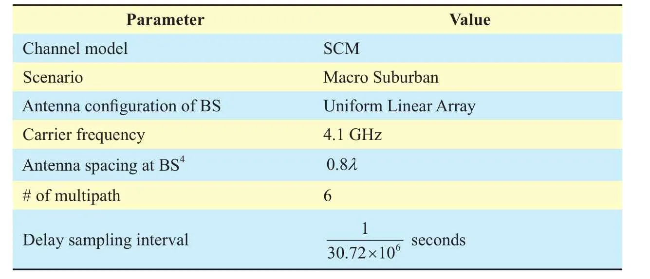
Table II SCM channel model parameters
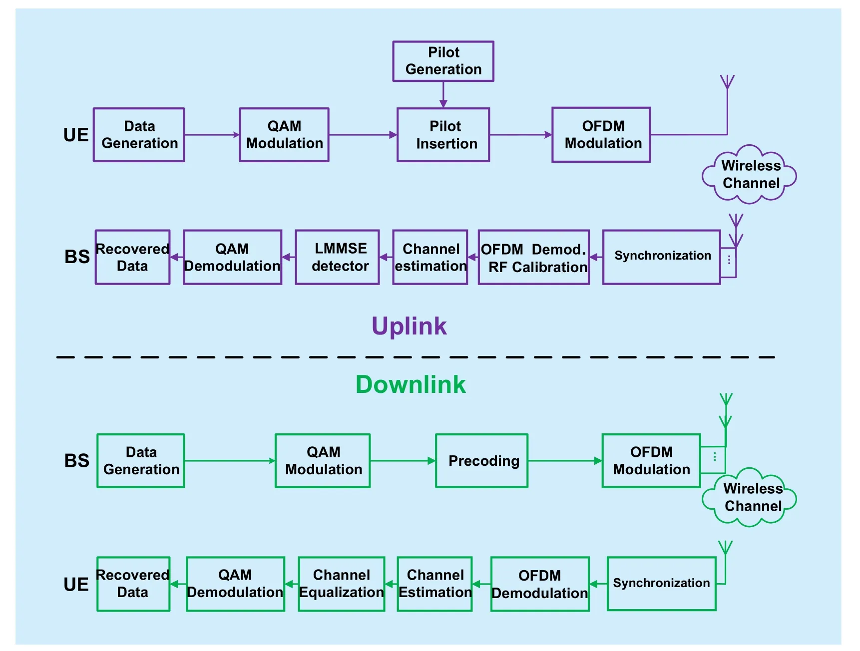
Fig. 4 System block diagram of the TDD-based 128 antenna massive MIMO system in link-level simulation.Top: uplink pilot/data transmission. Bottom: downlink pilot/data transmission
The uplink transmission begins after successful synchronization between BS and UE by PSS. In the uplink, if the current OFDM symbol is used for uplink pilot transmission,then pilot symbols (QPSK modulated) are generated and mapped into resource elements in accordance with the time-frequency resource grids in figure 3. Otherwise, raw data bits are generated, QAM modulated, and then mapped into resource elements in accordance with the time-frequency resource grids to be further processed, such as OFDM modulation.In OFDM modulation, inverse fast Fourier transform (IFFT) and cyclic prefixing (CP)are implemented. Then, either the pilot or data OFDM symbol is transmitted by the UE through the SCM channel. At the BS end,OFDM demodulation, i.e., fast Fourier transform (FFT) and CP removal, is carried out followed by RF calibration, LS channel estimation, and joint LMMSE detection. QAM demodulation is finally conducted to recover the raw data bits and calculate the bit error rate (BER).
The downlink adopts an inverse process of the uplink. First, raw data bits for multiple single-antenna users are generated at BS. After QAM modulation, precoding (based on the uplink channel estimates), and OFDM modulation, the users’ OFDM modulated signals are transmitted by the massive MIMO BS over the SCM channel. Notably, we assume that the channel is quasi-static within a time slot,so the SCM channel coefficients during one time slot do not change. However, channel reciprocity between the uplink and downlink is impaired due to the hardware mismatch. On the UE side, similar to the BS in the uplink,OFDM demodulation, LS channel estimation,maximum-ratio combining and QAM demodulation are conducted in sequence.

Fig. 5 Effect of reciprocity calibration under a different precoding matrix when M = 128, K = 12 and QPSK is used for the 12 single-antenna users. Top: BER of uplink (left)/downlink (right) data transmission without reciprocity calibration. Bottom: BER of uplink (left)/downlink(right) data transmission with reciprocity calibration.
3.3 Numerical results
Based on the link-level simulation, we investigate the impacts of reciprocity calibration under different precoding matrices, the BER for different users with different modulation,and the data throughput of the system.
Figure 5 shows the impact of reciprocity calibration in the uplink and downlink data transmission under different precoding schemes. Reciprocity calibration exerts a significant impact on downlink data transmission,but has a negligible impact on uplink data transmission. Regardless of whether reciprocity calibration is introduced or not, the BER of all the single-antenna users is 10-4at SNR=4 dB in the uplink. However, the performance of the downlink severely degrades without reciprocity calibration regardless of whether MRT or LMMSE precoding is employed. The reason is that the effective uplink channels,which contain the hardware impacts from BS’RX chains and UE’s TX chains, are well estimated by the uplink pilot. Thus, the data transmitted from multi-users are jointly processed at BS by making full use of the estimated effective channel coefficients. Nevertheless, the channel reciprocity in TDD mode is destroyed by the hardware mismatch between BS’ TX chains and BS’ RX chains. The precoding matrix constructed from the estimated effective channel in the uplink cannot effectively inhibit the interference in the downlink, so the performance of downlink data transmission is significantly degraded. With reciprocity calibration, LMMSE precoding outperforms MRT in downlink data transmission.
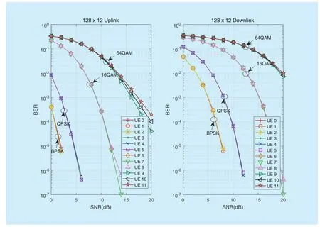
Fig. 6 BER for different users with different modulations in uplink and downlink for M = 128 and K = 12. BPSK is used for UE0-2, QPSK is used for UE3-5, 16-QAM is used for UE6-8, 64-QAM is used for UE9-11, and reciprocity calibration is also considered. Left: uplink data transmission. Right: downlink data transmission
Figs. 6 and 7 show the BER and throughput for different users under different modulation schemes. In figure 6, uplink data transmission outperforms the downlink transmission due to the joint processing at the BS. Comparison of figure 6 with figure 7 shows that a high modulation order results in poor BER performance but high throughput. Consequently, a tradeoff is made between system throughput and BER performance. In our prototyping system,to acquire improved BER to support video streaming application in the absence of channel coding, we select QPSK for all users in the uplink, which can achieve

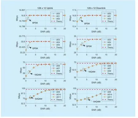
Fig. 7. Throughput of users when M = 128 and K = 12. The theoretical throughput of different QAM modulation under 20MHz bandwidth with OFDM utilized is presented as a baseline for different users, and BPSK is used for UE0-2, QPSK is used for UE3-5, 16-QAM is used for UE6-8, and 64-QAM is used for UE9-11. Left: uplink data transmission. Right: downlink data transmission with reciprocity calibration
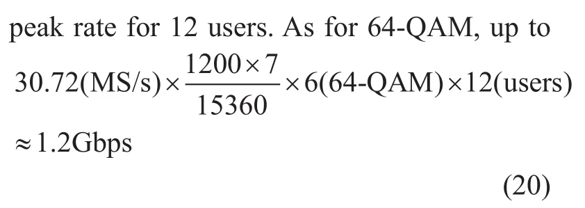
peak rate can be achieved over a 20 MHz bandwidth for 12 users at high SNR. 256-QAM can also be supported with the introduction of channel coding.
These numerical results provide several guidelines for our TDD-based massive MIMO prototype system design. First, with the assumption of a quasi-static channel during one slot, the designed frame structure presented in figure 2 operates well. This indicates that the frame structure is applicable to scenarios in which channel coherent time is equal to or larger than 0.5 ms. Second, as observed in(18), although much interference is induced by other users resulting from the rough pilot design, the simulation results reveal that the downlink data of multiple users can also be perfectly recovered with the aid of the downlink channel estimate. Third, reciprocity calibration is necessary especially in downlink transmission. Furthermore, relative reciprocity calibration, which means we only internally calibrate the BS relative to one of its antennas,is feasible and can be adopted in practical system.
In addition, a 128-antenna massive MIMO BS can serve the data transmission of 12 single-antenna users at the same time-frequency resource in both the uplink and downlink.More users (e.g., 24 users) can also be supported by reconfiguring the frame structure and making full use of time division multiple access. Finally, to successfully transmit multiple uplink video streaming in the absence of channel coding, the combination of QPSK (or 16-QAM) modulation scheme and LMMSE detector is optimal when the hardware power constraint is considered (e.g., the maximum output power at 4.1 GHz is 15 dBm), and the antennas are passive without a connected power amplifier.
IV. SYSTEM DESIGN AND EXPERIMENT SETUP
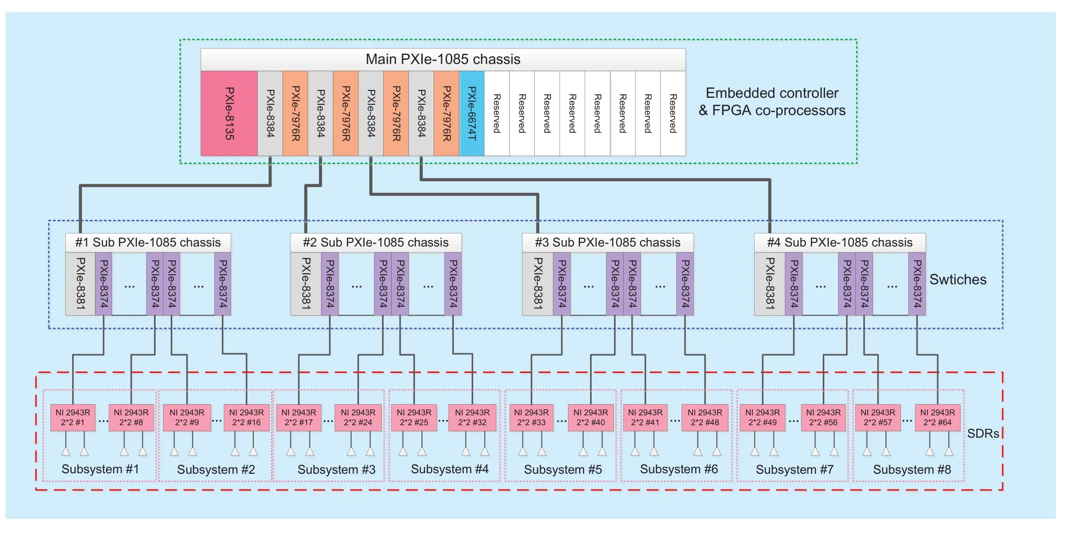
Fig. 8 System architecture of our TDD-based 128 antenna massive MIMO prototype system. The entire system framework is composed of PXIe-1085 chassis in a hierarchical design, where PXIe-1085 chassis serve as switches, data collected by NI 2943Rs will converge at each sub PXIe-1085 chassis, and the main PXIe-1085 chassis is equipped with both PXIe-8135 high-performance embedded controller and PXIe-7976R FPGA co-processor to enhance the data processing capability
In this section, we present the hardware design of the TDD-based 128-antenna massive MIMO prototype system including the system architecture and experiment setup. Uplink and downlink data transmission procedures along with hardware devices are also discussed in detail.
4.1 System architecture and experiment deployment
1) Overview of the system architecture:Combining the clock distribution module and the high data throughput peripheral component interconnect extensions for instrumentation(PXI) system, the system architecture of our TDD-based 128-antenna massive MIMO prototype system based on software defined radio platform (i.e., USRP-RIO manufactured by National Instruments) is shown in figure 15.
To alleviate the overwhelming processing burden of data transmission and signal processing due to the dramatically increased BS antenna array size, we have divided the 128-antenna massive MIMO prototype system into subsystems with each subsystem consisting of 16 antennas (8 NI 2943Rs). In addition,four FPGA co-processors (PXIe-7976R) are introduced into the main PXIe-1085 chassis to handle the massive baseband data. Distributive implementations of functionalities such as OFDM (de)modulation, MIMO detection,and precoding are realized in these NI 2943Rs and FPGA co-processors. Both the hardware and the software utilized by our system are built with commercially available products/solutions, which makes our system stable, customization friendly, and sufficiently accurate.
A brief introduction of all the hardware components involved in the system block diagram in figure 15 is given in the following.
● PXIe-1085 chassis: 3U PXI Express chassis with 18 slots, including 16 hybrid slots and one PXI Express system timing slot.Each hybrid slot has a bandwidth of 4 GB/s and can be connected with an NI 2943R through PXIe-8374.
● PXIe-8374: MXIe×4 cabled PCIe interface card, can be used to connect NI 2943R and the PXI chassis for data exchange with a real-time data transfer bandwidth up to 200 MHz and a maximum data transfer rate of 800 MB/s.
● NI 2943R: SDR nodes of USRP-RIO series, consists of a programmable FPGA(Xilinx Kintex-7) and two RF transceivers with a bandwidth of 40 MHz and a center frequency to be configured in the range of 1.2−6 GHz. The maximum transmitting power is 15 dBm.
● PXIe-8135: NI PXIe-8135 is a high-performance embedded controller based on Intel Core i7-3610QE processor with 2.3 GHz baseband frequency, 3.3 GHz quad-core CPU and dual-channel 1600 MHz DDR3 memory.
● PXIe-8384/PXIe-8381: ×8 Gen 2 cabled PCI Express interface suite, used to connect PXI chassis for the purpose of converging data from sub PXIe-1085 chassis to the main PXIe-1085 chassis.
● PXIe-6674T: Timing and trigger sync module with on-board highly stable 10 MHz OCXO (sensitivity of 50 ppb). This module is used to generate the clock signal and enlarge the trigger signal, which can then be routed among multiple devices such as PXI chassis and USRP RIOs to realize precise synchronization of timing and trigger signals across the whole system.
● PXIe-7976R: DSP-focused Xilinx Kintex-7 FPGA co-processor, used to help CPU process baseband data such as channel estimation and MIMO detector.
As can be observed in figure 15, the entire system framework is made with a PXIe-1085 chassis in a hierarchical design, where the PXIe-1085 chassis serves as switches. Data collected by USRP RIOs, e.g., NI 2943R,will converge at each sub PXIe-1085 chassis.Each sub PXIe-1085 chassis can connect up to 16 USRP-RIOs to construct a MIMO of size 32×32 and aggregates these MIMO data to the main PXIe-1085 chassis through PXIe-8384 and PXIe-8381. Thus four sub PXIe-1085 chassis can construct 128×128 MIMO.The main PXIe-1085 chassis is equipped with not only the PXIe-8135 high-performance embedded controller but also the PXIe-7976R FPGA co-processor to enhance the data processing capability.
At the bottom of figure 15, a total of eight subsystems, with each subsystem containing eight USRP RIOs, i.e., sixteen antennas are shown. In each subsystem, two of the eight USRP RIOs serve as data combiner and data splitter for this subsystem respectively. All sixteen antennas’ whole band (i.e. 20 MHz)baseband data will be grouped into consecutive data chunks and aligned with the antenna index in the data combiner in the uplink and the data splitter in the downlink. In the data combiner, baseband data are aggregated in the current subsystem and will be distributed to the sub-band processors (i.e. the four FPGA co-processors with each processing 5 MHz baseband data) for channel estimation and MIMO detection subsequently. While in data splitter, precoded baseband data are aggregated from sub-band processors and will then be distributed to sixteen antennas in the current subsystem. The embedded controller is responsible for finishing the hardware configuration and initialization, displaying the received constellation in the uplink and generating raw bits for multi-users (MUs) in the downlink.
A picture of the assembled 128-antenna base station is shown in figure 16. An 8×16 uniform planar antenna array composed of dipole element is allocated in front of the rack and connect with NI 2943Rs through SMA cables. Each NI 2943R has two RF chains.Thus, our system needs 64 NI 2943Rs which are divided equally and installed on 4 cabinets.Each cabinet is equipped with 16 NI 2943Rs and each PXIe-1085 chassis makes up 2 subsystems except the second one from the left,which is the main cabinet and consequently equipped with two PXIe-1085 chassis. In the main cabinet, the middle chassis is one of the sub PXIe-1085 chassis and the bottom is the main PXIe-1085 chassis.
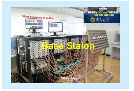
Fig. 9 Picture of the assembled BS. The 816 uniform planar antenna array constituted by dipole element is allocated in front of the rack and connect with NI 2943Rs through SMA cables. 64 NI 2943Rs are divided equally and installed on 4 cabinets,and each cabinet is equipped with 16 NI 2943Rs
2) Synchronization: Timing and synchronization are critical for multi-device systems,especially a massive MIMO system that needs the deployment of a large number of radio devices. Two challenges in timing and synchronization exist for our massive MIMO system.One is the timing and synchronization among radio devices at BS, and the other is timing and synchronization between BS and UEs. To solve the former problem, a clock and trigger signal distribution network is established with the use of the OctoClock module at BS. Figure 10 presents the clock and trigger signal distribution network. The OctoClock module in the diagram is a signal amplifier and distribution module, and it can use an external 10 MHz reference clock as clock source and an external pulse per second (PPS) signal as a trigger signal source. The input clock signal and trigger signal will be then amplified and distributed to eight channels in the top-level OctoClock to synchronize the timing and trigger signals for the second-level eight OctoClock modules or eight USRP-RIO devices depending on the connected peripheral.

Fig. 10 Clock and trigger signal distribution network. Firstly, the timing and sync module PXIe-6674T receives a digital trigger signal from the master NI 2943R and generates a stable and precise 10MHz reference clock at local. The digital trigger signal and 10MHz reference clock are subsequently forwarded to the top-level OctoClock module by PXIe-6674T. Then, the toplevel OctoClock module amplifies the received reference clock signal and trigger signal and distributes them to eight second-level OctoClock modules to do further amplification and distribution. Finally, each OctoClock module at second-level amplifies and distributes the reference clock signals and trigger signals to eight USRP-RIO devices respectively
The principle of the clock and trigger signal distribution network can be summarized as follows: First, the timing and sync module PXIe-6674T, which has an oven-controlled crystal oscillator (OCXO), receives a digital trigger signal from the master NI 2943R and generates a stable and precise 10 MHz reference clock (sensitivity of 50 ppb) locally.The digital trigger signal and 10 MHz reference clock are subsequently forwarded to the top-level OctoClock module by PXIe-6674T.Then, the top-level OctoClock module amplifies the received reference clock signal and trigger signal and distributes them to eight second-level OctoClock modules for further amplification and distribution. Finally, each second-level OctoClock module amplifies and distributes the reference clock signals and trigger signals to eight USRP-RIO devices. Therefore, all 128 antennas of the 64 USRP-RIOs share the same reference clock signal and trigger signal, and all radio devices at BS can start data collection and generation synchronously.
As for timing and synchronization between BS and UEs, we use PSS similar to LTE: UEs transmits PSS to BS first. After receiving PSS, BS performs a cross correlation of the received PSS with local PSS. Then, the peak index among a 10 ms radio frame is found and conveyed to 64 USRP-RIOs by the embedded controller at BS. Finally, all the radio devices are aligned, and synchronization between BS and UEs is successfully achieved. Note that carrier offset compensation needs to be considered because of the sampling clock frequency offset between BS and UEs.
3) Reciprocity Calibration: On the basis of the numerical results in the link-level simulation, beamforming antennas need to have relatively accurate channel state information(i.e., a constant multiplicative factor across base station antennas). Hence, relative reciprocity calibration is feasible, and we realize the relative calibration method utilized in our link-level simulation, which is similar to[16], [21]. The calibration process is shown in Algorithm 1. BS needs to finish RF configuration and initialization before the start of the calibration process, and no interference should occur during calibration.
The calibration process can be summarized as follows: 1) Each antenna k(k=1,…,M) on the base station transmits the reference waveform, and all M antennas (including the kth one) at BS receive and note it down. 2) One of the M antennas is selected as the reference antenna mref, and for this reference antenna,the reciprocity coefficients to (and from) all other base station antennas are calculated. 3)The coefficients for each antenna over all the subcarriers are averaged. 4) All reciprocity coefficients are sent to USRP-RIOs. Measured by our prototyping system, the aforementioned calibration process takes only several minutes to finish. Nevertheless, because base station antennas share common reference clocks,these calibration coefficients are stable over long periods, and thus, we update these coefficients only once per day during the initialization of BS.
4) Antenna Array: A 128-element uniform planar array (UPA) is designed to serve as the base station antenna array of our massive MIMO prototype system. As shown in figure 16, this antenna array is constructed on a lowcost reference design, and all elements on the antenna array are printed dipoles and mounted above metallic reflectors. The operation band is 3.8-4.3 GHz and the antenna spacing is 0.8λ @4.1 GHz both in the horizontal and vertical directions. The measured performance of the antenna element is tabulated in Table 3. The dipole element is measured by using Agilent’s 8720ET vector network analyzer and Microwave Vision’s Starlab near the field antenna measurement system. As can be observed from figure 11 and Table 3, the standing wave ratio of the dipole is lower than 1.4 from 3.8-4.3 GHz, and the dipole exhibits a stable unidirectional, linearly polarized radiation pattern within its impedance bandwidth.The half-power beam width of the E- and the H-plane is 55° and 100°, respectively. The front-to-back ratio of the antenna is higher than 22 dB, and the in-band average gain is 7.7 dBi.
5) User Equipment: Four USRP-RIOs (i.e.,NI 2943Rs) are used at the terminal ends to emulate eight single-antenna users. To simplify the hardware implementation of synchronization between BS and UEs, a 10 MHz reference clock signal is shared among the four USRP-RIOs. The details of hardwareimplementation for each single-antenna user are provided in figure 4. As can be observed in figure 4, in the user side, data generation/recovery is implemented in the embedded controller or the computer, and the rest is programmed in FPGA contained in USRP-RIOs.
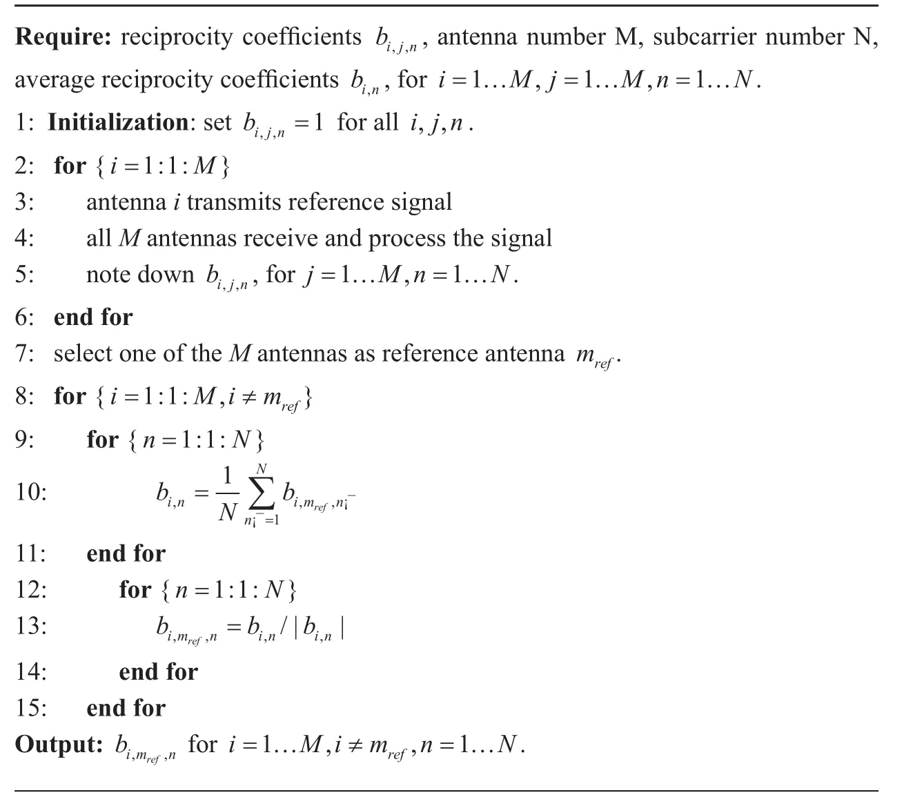
Algorithm 1 Relative reciprocity calibration process
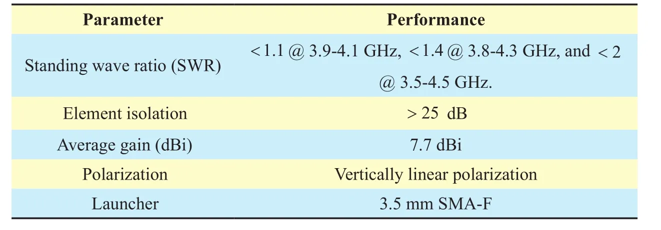
Table III Measured antenna performance
6) Experiment Deployment: The experiments are conducted in a typical indoor office environment6An outdoor environment test is under our consideration in future work., and the deployment is presented in figure 11. The 128-element UPA with a height of 1.2 m is fixed near the chassis, and the eight horn antennas related to eight single-antenna users are placed at eight line-ofsight7We also demonstrate non-line-of-sight tests by placing a metal obstacle in the middle of BS and UEs. Results verify that the typical indoor office environment is rich scattered.(LOS) points and marked with 1,2,…8.A series of experiments is carried out in the deployment, including MU massive MIMO channel measurement, multiple video streaming transmission in the uplink, and MU beamforming data transmission in the downlink.Experiment results are illustrated in Section V.

Fig. 11 Radiation patterns of principal planes, H plane is parallel to the ground and E plane is perpendicular to the ground, (a) H plane @3:8 GHz, (b) E plane @3:8 GHz, (c) H plane @4:1 GHz, (d) E plane @4:1 GHz
4.2 Link-level transmission procedure in hardware
Figure 13 presents the system block diagrams related to hardware implementation for both uplink and downlink. To improve system scalability and meet latency and hardware resource constraints, a total of eight subsystems are divided in the base station, which is consistent with figure 15. Each subsystem contains eight USRP-RIOs, where the first USRP-RIO (NI 2943R) serves as a data combiner in the uplink and the last serves as data splitter in the downlink. Four FPGA co-processors are introduced to improve the computational capability, and each FPGA co-processor is responsible for the baseband processing (i.e., LS channel estimation, LMMSE detection, and precoding) of 5 MHz bandwidth from 128 antennas. Details of the link-level transmission procedure in hardware are provided as follows:
Uplink Data Transmission Procedure.
As shown in the figure, for the uplink, the RF signals acquired by 64 NI 2943Rs, i.e., 128 antennas, first go through the 128 RF chains and perform low noise amplification, down conversion, and analog-to-digital conversion(ADC). Then, the high-rate samples (e.g.,120 MS/s) from ADC are sent to each NI 2943R’s FPGA for IQ imbalance correction,frequency shift correction, digital down sampling8The raw high rate samples from ADC are down sampled to the specified sampling rate in this module.For 15 KHz subcarrier spacing and 2048 FFT size, the specified sampling rate is 30.72 MS/s. The operation of digital up sampling in downlink is in the reverse., and OFDM demodulation. After applying reciprocity calibration coefficients over all subcarriers, obtained valid baseband data from 16 antennas in each subsystem are aggregated and aligned in their data combiners. These aligned baseband data are then distributed to four FPGA co-processors for LS channel estimation and QR decomposition-based LMMSE detection through switches (i.e., PXIe-1085).Finally, these recovered data are conveyed to the embedded controller by FPGA co-processors for display and further analysis. In our prototyping system, the conversion accuracy of ADC is 12 bit. Thus available data throughput per RF chain is

Each subsystem contains 16 RF chains.Therefore, the available data throughput per subsystem are 806.4 MB/s. A total of eight subsystems are connected with the main switch. Thus the available data throughput in main switch will be
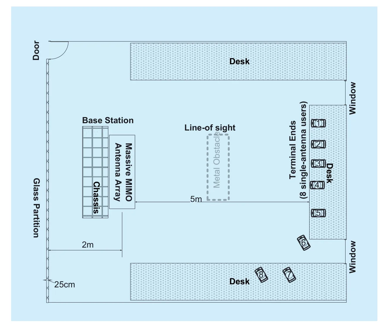
Fig. 12 The measured environment and experiment deployment. The 128-element UPA with 1:2m height is fixed near the chassis, and the eight horn antennas related to eight single-antenna users is placed at eight points marked with 1; 2; : : : 8


Fig. 13 System block diagram related to hardware implementation for both uplink and downlink data transmission at base station. A total of eight subsystems is divided in the base station, each subsystem contains eight USRP-RIOs, where the first USRP-RIO (NI 2943R) serves as data combiner in uplink and the last serves as data splitter in downlink. Four FPGA co-processors are introduced to improve the computational capability, and each FPGA co-processor is responsible for the baseband processing (i.e., LS channel estimation, LMMSE detection and precoding) of 5MHz bandwidth from 128 antennas
Downlink Data Transmission Procedure.
The process of downlink data transmission is opposite that of uplink. For downlink, raw data bytes generated by the embedded controller for multiple users are first transferred to four FPGA co-processors. The precoding matrices used for downlink beamforming are pre-obtained during uplink channel sounding at the same slot and are stored in the memories of the four FPGA co-processors. Each FPGA co-processor is responsible for precoding the downlink data of 5 MHz bandwidth of 128 antennas by using precoding matrices stored on board. The precoding algorithm is LMMSE precoding. Then, these precoded data are distributed to eight data splitters that correspond to eight subsystems through switches. When each data splitter aggregates its 16 antennas’whole band data, these data will be distributed to eight NI 2943Rs (i.e., 16 antennas) in the current subsystem for OFDM modulation.After OFDM modulation, digital up-sampling,frequency shift correction, and IQ imbalance correction in the FPGA of each NI 2943R, the high-rate data bytes will be conveyed to each RF chain for digital-to-analog conversion and up conversion, and then finally transmitted by antennas.
V. EXPERIMENT RESULTS
Experiment results are presented and discussed in this section. These results include MU massive MIMO channel measurement,multiple video stream transmission in the uplink, MU beamforming data transmission in the downlink, and the performance of the relative reciprocity calibration method.
a) MU Massive MIMO Channel Measurements.To measure the MU massive MIMO channel, frequency orthogonal pilots are transmitted to BS by 8 single-antenna users9Twelve or more users can be supported by introducing more USRP-RIOs in the user equipment side or by reconfiguring the frame structure.at the same time-frequency resource during channel sounding period, i.e., UL pilot OFDM symbol in the frame structure. After receiving pilot signals, the BS estimates each user’s channel matrices by using LS channel estimation with pre-stored local pilot sequences as illustrated in Section II. Then, the measured channel matrices are further processed and analyzed to obtain results, including channel time-domain impulse response, channel correlation matrix on the BS side, and channel correlation matrices on the user side, which are presented in figure 14.
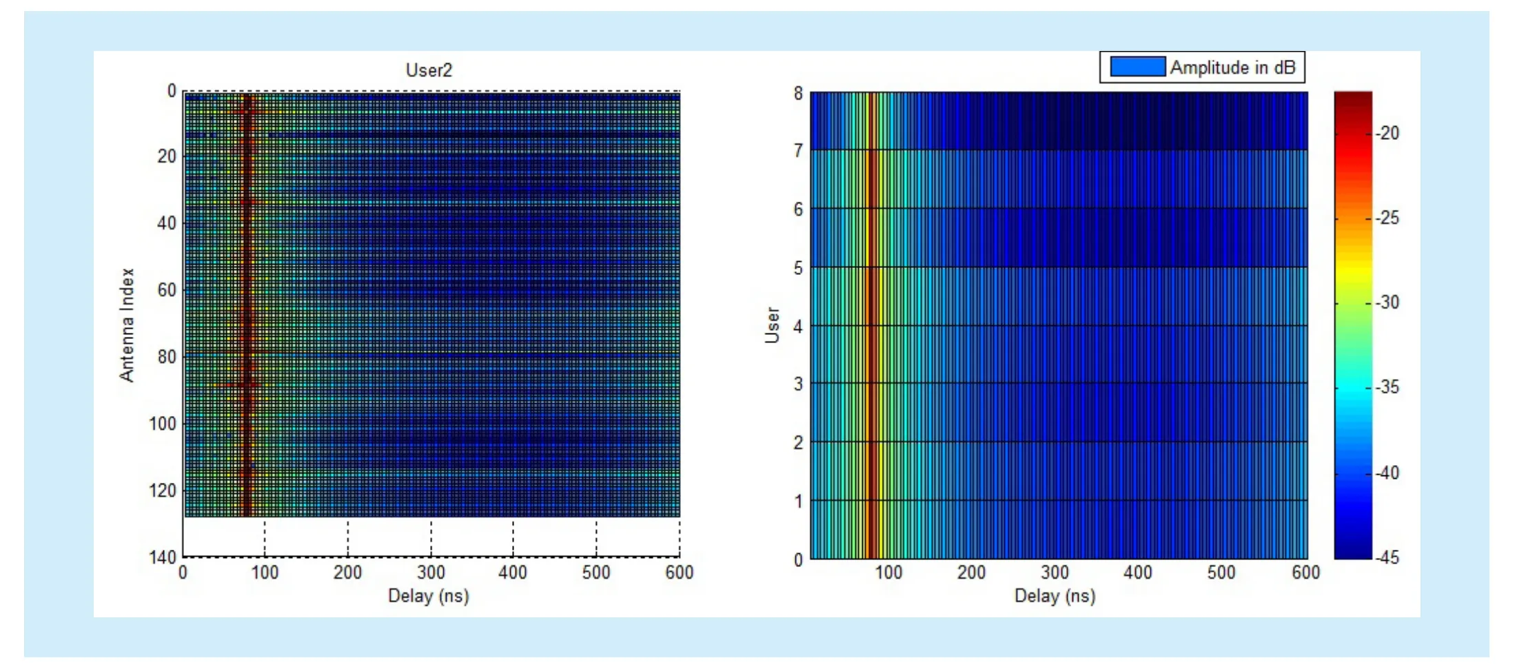
Fig. 14 Left: Time-domain impulse response of uplink channel for User2, The horizontal axis is delay (ns), the vertical axis is the antenna index, and 128 antennas are configured in BS. Right: Time-domain impulse responses of uplink channel for eight single-antenna users, averaged on 128 antennas
The time-domain impulse responses on the left side of figure 14 show that for User2, a distinctive planar wavefront with an approximately 33 ns delay spread exists despite the little difference among different antennas. The right side of figure 14 shows that the averaged time-domain impulse responses of uplink channel for eight single-antenna users also exhibit an approximately 33 ns delay spread.Combined with the sample rate of 30.72 MS/s(i.e., 33 ns) for the 20 MHz bandwidth, the frequency selectivity of the channel is not severe in the current deployment. In addition,the distinctive planar wavefront of the righthand side plot of figure 23 also verifies that the eight users are well time-aligned in the uplink.
Figs. 15 and 16 show the channel correlation matrix. For the channel correlation matrix on the BS side, signal strength is not concentrated on the diagonal line but on the border of squares. This finding is consistent with the geometry of the antenna array (8×16 UPA) used in our prototyping system. As for the UEs, signal strength is concentrated on the diagonal line as expected, which indicates that the single-antenna users are independent and the environment is rich scattered. More channel measurement results can be referred to in[32].
b) Massive MIMO MU Uplink and Downlink Data Transmission.According to the designed frame structure provided in figure 2, a real-time uplink and downlink data transmission test is conducted with the carrier frequency configured as 4.1 GHz. The test results are shown in figure 16, where eight single-antenna users transmitted video streams to BS with the QPSK modulation scheme. The base station successfully recovered the eight video streams and displayed them in the monitor, which validates the

peak rate achieved in the uplink. Constellation data transmission with 64-QAM modulation scheme or 256-QAM modulation scheme can also be achieved with peak rate of 806.4 Mbps and 1.075 Gbps respectively. In the downlink, the QPSK modulation scheme is used for six of these single-antenna users, and the other two use 16-QAM, which manifests an achieved peak rate of 470.4 Mbps over 20 MHz bandwidth. In addition, the maximum spectral efficiency we achieved is by the usage of 256-QAM and six OFDM symbols used as uplink data transmission per slot under twelve single-antenna users. Note that the maximum spectral efficiency can still be improved by increasing the valid subcarriers from 2048 FFT size. For example, we can use 1400 of the 2048 subcarriers to transmit data and thus achieve a maximum spectral efficiency of 80.64 bit/s/Hz.
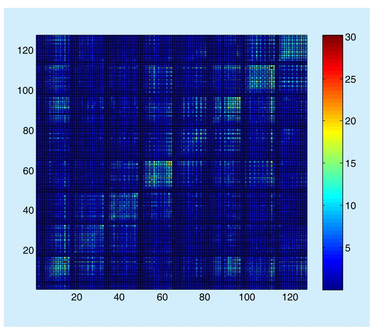
Fig. 15 Channel correlation matrix on the BS side
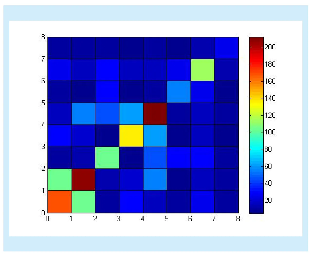
Fig. 16 Channel correlation matrix on the user side


Table IV Hardware utilization of Xilinx Kintex-7 FPGAs for the proposed TDD-based 128-antenna massive MIMO system
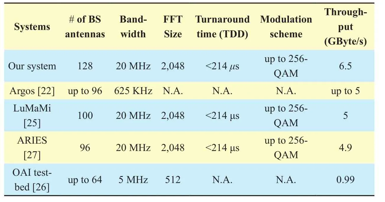
Table V Implementation comparison with the state-of-the-art massive MIMO prototype systems
c) Reciprocity Calibration.To verify the performance of the relative reciprocity calibration method, we performed several trials by setting different antennas as the reference antenna or by ensuring that the UEs continue to transmit during the calibration process. The results shown in figure 19 imply that when interference (e.g., UEs are transmitting signals)occurs during the calibration process or the selected reference antenna is near the border of the antenna array (inducing low SNR for the antennas in the opposite side due to the large array size), the reciprocity calibration coefficients will be inaccurate and UEs can-not recover the data they received in the downlink because of the large interference. Therefore,the geometry of the antenna array needs to be considered.

Fig. 17 Left: Reciprocity calibration coefficients. The vertical axis represents the amplitude of the obtained calibration coefficients over the 1200 subcarriers. Right: The constellation of detected data for two single-antenna UEs in the downlink
In addition, the vertical axis in figure 19 represents the amplitude of the obtained cali-bration coefficients over the 1200 subcarriers.From the green and blue lines, we can determine that the practical calibration coefficients for all antennas maintain an almost constant amplitude over a 20 MHz bandwidth, which clarifies the availability of the hardware mismatch model adopted in the link-level simulation and the validity of the relative calibration method.
d) Hardware Performance Analysis.Hardware resource utilization for each module of the 128-antenna massive MIMO system is given in Table 4. Given the task of routing sub-band 128-antenna data and performing LS channel estimation, LMMSE detection,and LMMSE precoding, more than half of the hardware resources are used in the FPGA of sub-band processors respectively. For instance,the ratio of the used DSP48E is 72.9%, which mainly results from the pseudo-inverse computation of the 128×12 matrix. The considerable hardware resource usage severely hinders the introduction of error correction codes,such as turbo or polar codes. Therefore, advanced detectors, which fully exploit massive MIMO system characteristics with less realization complexity, should be introduced, such as successive over relaxation-based detector. A robust channel estimator, e.g. LMMSE channel estimator, also needs to be considered to acquire more accurate channel state information.
As for resource utilization in data splitter and data combiner, for the sake of data routing and aligning, the majority of RAMs are used,but many unused resources still exist, such as LUTs and DSP48Es. These resources are sufficient for the introduction of new radio interface technologies, e.g., filter bank multi-carrier, which is also considered in our future work. Table 5 presents the implementation comparison among existing massive MIMO prototype systems.
Compared with Argos and OAI testbed,our system, LuMaMi, and ARIES, are all operated with 2048 FFT size and 20 MHz bandwidth. Moreover, for our system, LuMa-Mi, and ARIES, the turnaround time between uplink and downlink transition are all less than 214 μs (i.e., three-OFDM-symbol duration).Moreover, with a configured 20 MHz bandwidth and 128 base station antennas, the data throughput of our implemented prototype system achieves 6.5 GByte/s, which significantly highlights the tremendous real-time baseband data processing burden.10The hardware resource utilization of the other NI 2943Rs in each subsystem(except data splitter and data combiner) is the same as that of the data combiner. This configuration is created from the consideration of serving the other six NI 2943Rs as data combiner candidates. Thus, we can reconfigure the system flexibly and achieve enhanced system robustness.
VI. CONCLUSION
In this paper, we presented the design and implementation of a TDD-based 128-antenna massive MIMO prototype system from theory to reality. The analytical signal model and link-level simulation related to a practical massive MIMO system have been established.Both uplink video transmission and downlink LMMSE beamforming have also been realized. The maximum spectral efficiency we achieved is 69.12 bit/s/Hz. We also studied reciprocity calibration algorithm in our practical TDD-based massive MIMO system.Comparisons with the state-of-the-art prototyping systems showed the advantages of not only this system but also the proposed design methodology, which can be further employed to design more massive and practical systems.Conclusively, our TDD-based 128-antenna massive MIMO prototype system provides a sufficient but scalable reference design for research on massive MIMO system. Future work will be directed toward introducing an LMMSE channel estimator and advanced detector in our system. Other baseband processing techniques such as polar coding and advanced computation architecture [33] will also be considered in the near future.
ACKNOWLEDGEMENT
The authors would like to thank Southeast University graduates Feng Ji and Zijian Han,Nanjing University of Posts and Telecommunications graduate Yu Yu, and Zhiya Information Technology engineers Xiaolong Miao and Wankai Tang for their assistance with the system architecture design and implemen-tation. This work was supported in part by the National Science Foundation (NSFC) for Distinguished Young Scholars of China with Grant 61625106, the National Natural Science Foundation of China under Grant 61531011,and the Hong Kong, Macao and Taiwan Science and Technology Cooperation Program of China (2016YFE0123100).
[1] ITU-R. “IMT Vision – Framework and overall objectives of the future development of IMT for 2020 and beyond’. Tech. Rep., 2015. [Online].Available: https://www.itu.int/dms\_pubrec/itu-r/rec/m/R-REC-M.2083-0-201509-I!!PDF-E.pdf
[2] F. Boccardi, R. W. J. Heath, A. Lozano, T. L.Marzetta, and P. Popovski, “Five disruptive technology directions for 5G,’ IEEE Commun. Mag.,vol. 52, no. 2, pp. 74-80, Feb. 2014.
[3] T. L. Marzetta, “Noncooperative cellular wireless with unlimited numbers of base station antennas,’ IEEE Trans. Wireless Commun., vol. 9, no.11, pp. 3590-3600, Nov. 2010.
[4] X. Li, T. Jiang, S. Cui, J. An, and Q. Zhang, “Cooperative communications based on rateless network coding in distributed MIMO systems,’IEEE Wireless Commun., vol. 17, no. 3, pp. 60-67,Jun. 2010.
[5] F. Rusek, D. Persson, B. K. Lau, E. G. Larsson, T. L.Marzetta, O. Edfors, and F. Tufvesson, “Scaling up MIMO: Opportunities and challenges with very large arrays,’ IEEE Signal Process. Mag., vol.30, no. 1, pp. 40-60, Jan. 2013.
[6] E. G. Larsson, O. Edfors, F. Tufvesson, and T. L.Marzetta, “Massive MIMO for next generation wireless systems,’ IEEE Commun. Mag., vol. 52,no. 2, pp. 186-195, Feb. 2014.
[7] J. Zhang, C.-K. Wen, S. Jin, X. Gao, and K.-K.Wong, “On capacity of large-scale MIMO multiple access channels with distributed sets of correlated antennas,’ IEEE J. Sel. Areas Commun.,vol. 31, no. 2, pp. 133-148, Feb. 2013.
[8] Q. Zhang, S. Jin, K.-K. Wong, H. Zhu and M.Matthaiou, “Power scaling of uplink massive MIMO systems with arbitrary-rank channel means,’ IEEE J. Sel. Topics Signal Process., vol. 8,no. 5, pp. 966-981, Oct. 2014.
[9] L. Fan, S. Jin, C.-K. Wen, and H. Zhang, “Uplink achievable rate for massive MIMO systems with low-resolution ADC,’ IEEE Commun. Lett., vol.19, no. 12, pp. 2186-2189, Dec. 2015.
[10] S. Jin, X. Wang, Z. Li, K.-K. Wong, Y. Huang and X. Tang, “On massive MIMO zero-forcing transceiver using time-shifted pilots,’ IEEE Trans.Veh. Technol., vol. 65, no. 1, pp. 59-74, Jan. 2016.
[11] H. Xie, F. Gao, and S. Jin, “An overview of lowrank channel estimation for massive MIMO systems,’ IEEE Access, vol. 4, pp. 7313-7321, 2016.
[12] C.-K. Wen, C.-J. Wang, S. Jin, K.-K. Wong, and P.Ting, “Bayes-optimal joint channel-and-data estimation for massive MIMO with low-precision ADCs,’ IEEE Trans. Signal Process., vol. 64, no.10, pp. 2514-2556, May. 2016.
[13] H. Xie, F. Gao, S. Zhang, and S. Jin, “A unified transmission strategy for TDD/FDD massive MIMO systems with spatial basis expansion model,’ IEEE Trans. Veh. Technol., vol. 66, no. 4,pp. 3170-3184, Apr. 2017.
[14] E. G. Larsson, et al. “Teaching the Principles of Massive MIMO: Exploring reciprocity-based multiuser MIMO beamforming using acoustic waves,’ IEEE Signal Process. Mag. vol. 34, no. 1,pp. 40-47, Jan. 2017.
[15] H. Q. Ngo, E. G. Larsson, and T. L. Marzetta,“Energy and spectral efficiency of very large multiuser MIMO systems,’ IEEE Trans. Commun.,vol. 61, no. 4, pp. 1436-1449, April 2013.
[16] J. Vieira, F. Rusek, O. Edfors, S. Malkowsky, L.Liu, and F. Tufvesson. (2017, Feb.). Reciprocity calibration for massive MIMO: Proposal, modeling and validation [Online]. Available:https://arxiv.org/pdf/1606.05156.pdf
[17] W. Zhang, H. Ren, C. Pan, M. Chen, R. C. de Lamare, B. Du, and J. Dai, “Large-scale antenna systems with UL/DL hardware mismatch:achievable rates analysis and calibration,’ IEEE Trans. Commun., vol. 63, no. 4, pp. 1216-1229,April 2015.
[18] H. Wei, D. Wang, H. Zhu, J. Wang, S. Sun, and X.You, “Mutual coupling calibration for multiuser massive MIMO systems,’ IEEE Trans. Wireless Commun., vol. 15, no. 1, pp. 606-619, Jan. 2016.
[19] H. Yang, and T. L. Marzetta, “Performance of conjugate and zero-forcing beamforming in large-scale antenna systems,’ IEEE J. Sel. Areas Commun., vol. 31, no. 2, pp. 172-179, Feb. 2013.
[20] F. Edman, and V. Owall, “A scalable pipelined complex valued matrix inversion architecture,’in Proc. 2005 IEEE Int. Symp. Circuits, Syst., vol. 5,Kobe, Japan, May 2005, pp. 4489-4492.
[21] C. Shepard, H. Yu, N. Anand, E. Li, T. Marzetta, R.Yang, and L. Zhong, “Argos: Practical many-antenna base stations,’ in Proc. 2012 Annual Int.Conf. Mobile Comput. Netw., ACM, 2012, pp. 53-64.
[22] C. Shepard, H. Yu, and L. Zhong, “ArgosV2: A flexible many-antenna research platform,’ in Proc. 2013 Annual Int. Conf. Mobile Comput. Netw.,ACM, 2013, pp. 163-166.
[23] C. W. Shepard, “Argos: Practical base stations for large-scale beamforming,’ Ph.D. dissertation, Rice University, 2012.
[24] J. Vieira, S. Malkowsky, K. Nieman, Z. Miers, N.Kundargi, L. Liu, I. Wong, V. {”O}wall, O. Edfors,and F. Tufvesson, “A flexible 100-antenna testbed for massive MIMO,’ in Proc. IEEE Global Commun. Conf. Workshops, 2014, pp. 287-293.
[25] S. Malkowsky et al. (2016, Dec.). The World’s First Real-Time Testbed for Massive MIMO: Design,Implementation, and Validation [Online]. Available:http://arxiv.org/pdf/1701.01161.pdf
[26] X. Jiang et al. (2016, Aug.). OpenAirInterface massive MIMO testbed: A 5G innovation platform[Online]. Available:http://www.openairinterface.org/?page\_id=1760
[27] N. Choubey, and A. Yazdan. (2016, April).Introducing Facebook’s new terrestrial connectivity systems Terragraph and Project ARIES [Online]. Available:https://code.facebook.com/posts/1072680049445290/introducing-facebook-s-new-terrestrial-connectivity-systems-terragraph-and-project-aries/
[28] D. Wubben, R. Bohnke, V. Kuhn, and K.-D. Kammeyer, “MMSE extension of V-BLAST based on sorted QR decomposition,’ in Proc. 2003 IEEE Veh. Technol. Conf., vol. 1, Oct. 2003, pp. 508-512.
[29] M. Myllyla, J.-M. Hintikka, J. R. Cavallaro, M.Juntti, M. Limingoja, and A. Byman, “Complexity analysis of MMSE detector architectures for MIMO-OFDM systems,’ in Proc. 2005 Asilomar Conf. Signals, Syst., Comput., California, USA,Oct.-Nov. 2005, pp. 75-81.
[30] “Spatial channel model for multiple input multiple output (MIMO) simulations,’ 3GPP TR 25.996 V6.1.0, Sep. 2003.
[31] R. Rogalin, O. Y. Bursalioglu, H. C. Papadopoulos, G. Caire, and A. F. Molisch, “Hardware-impairment compensation for enabling distributed large-scale MIMO,’ in Proc. 2013 IEEE Inf.Theory Applications Workshop, Feb. 2013, pp.1-10.
[32] Y. Yu, F. P. Cui, J. She, Y. Liu, X. Yang, W.J. Lu, S.Jin, and H.B. Zhu. “ Measurement and empirical modeling of massive MIMO channel matrix in real indoor environment,’ in Proc. Int. Conf.Wireless Commun. Signal Processing (WCSP), Oct.2016, pp. 1-5.
[33] X. Yang, Z. Huang, B. Han, S. Zhang, C.-K. Wen,F. Gao, and S. Jin, “RaPro: A Novel 5G Rapid Prototyping System Architecture,’ IEEE Wireless Commun. Lett., vol. 6, no. 3, pp. 362-365, June.2017.
- China Communications的其它文章
- Radio Access Network Slicing Based on C/U Plane Separation
- Multi-User Detection for Spatial Modulation toward 5G Wireless Communications
- Clustering of Virtual Network Function Instances Oriented to Compatibility in 5G Network
- Contract-Based Content Delivery in 5G Converged Networks
- Resource Allocation in D2D-Aided High-Speed Railway Wireless Communication Systems: A Matching Theory Approach
- On Uplink Non-Orthogonal Multiple Access for 5G:Opportunities and Challenges

