Applications of Deep Mixing to Earthquake Disaster Mitigation
Masaki+KITAZUME


Abstract:In Japan,soft alluvial clay ground has frequently encountered in on land and marine constructionsThe ground is so soft and compressible large settlement and failure can occurSandy soil has relatively better properties for compressibility,but liquefaction might happen during earthquakes in the case of loose and saturated conditionMany earthquakes occur each year in Japan,in which the 1995 Hyogoken-Nambu earthquake and the 2011 Tōhoku earthquake induced both a humanitarian crisis and massive economic impactsAs liquefaction which occurs in a loose and saturated sand layer,inducing quite large damages of infrastructures,the importance of liquefaction mitigation has been emphasized to minimize earthquake disasters for many yearsMany kinds of ground improvement techniques based on various principles have been developed for earthquake disaster mitigationAmong them,the deep mixing method(DMM),one of the insitu cement stabilization techniques,was developed in 1970s in Japan and has been often applied to improvement of clayey and sandy soilsRecently,the grid type of DMM has also been applied to prevent liquefaction,where the grid of stabilized column walls function to restrict generation of excessive pore pressure by confining the soil particle movement during earthquakesThe improvement effect of the method was first evaluated in the 1995 Hyogoken-Nambu earthquakeIn this paper,some applications of deep mixing method to earthquake disaster mitigation are briefly introduced
Keywords:deep mixing method,earthquake,liquefaction,disaster mitigation
CLC Number:TU473Document Code:AArticle ID:1000-0666(2017)01-0029-06
Introduction
Soft alluvial clay ground is wildly distributed in Japan, and many structures have to be built on it Obviously, this ground has a deadly defect, liquidation, which will destroy the stability of the structures and even cause the buildings to collapse under the seismic actionIn fact,port and harbor facilities at Kobe Port were heavily damaged in the 1995 Hyogoken-Nambu earthquake,where gravity type of sea revetments displaced a couple of meters towards sea together with large ground settlement at backfill yardTable 1 shows the amount of damage to port facilities caused by strong earthquake(Noda,1991),and demonstrates quite large difference between conditions and without liquefactionAccording to the Table 1,when liquefaction takes place,the amount of earthquake disaster is about 20 to 50 times larger than that of without liquefactionThis highlights the importance of liquefaction mitigation to minimize earthquake disasters
There are many kinds of soil stabilization techniques developed and available in Japan for countermeasure of stability,ground deformation and liquefactionAmong these techniques,the deep mixing method,one of the insitu cement stabilization techniques,was developed in 1970s in Japan and has been frequently applied to improvement of clayey and sandy soils(Kitazume,Terashi,2013).Recently,the grid type of DMM has been often applied to prevent liquefaction,where the grid of stabilized column walls function to restrict generation of excessive pore pressure by confining the soil particle movement during earthquakesThe improvement effect of the method was first evaluated in the 1995 HyogokenNambu earthquakeIn this paper,some applications of deep mixing method to earthquake disaster mitigation are briefly introducedTable 1Comparison of amount of damage caused by some Japan earthquake
EarthquakeMagnitudePortSoil typeMaxaccel/galLiquefactionDamage(million yen)Niigata,196475NiigataSand159Yes49980*Tokachi Oki,196879HachioheSand233No1980*Miyagiken Oki,197874ShiogamaClay273No160*74IshinomakiSand195~210Yes3008*Urakawa Oki,198273MuroranSand164No120Nihonkai Chubu,198377AkitaSand205Yes6400Note:*converted into 1978 prices地震研究40卷第1期Masaki KITAZUME:Applications of Deep Mixing to Earthquake Disaster Mitigation1Deep Mixing Method
11Outline of the Method
Deep Mixing Method(DMM),an insitu admixture stabilization technique using cement and/or lime as a binder,has been applied in many construction projects for various improvement purposes(Kitazume,Terashi,2013).DMM was put into practice in Japan in the middle of 1970s to improve soft marine deposits,and was spread into China,South East Asia,and recently to the other part of the worldTwo decades of practice has made equipment improved,binders changed,and applications diversifiedLime is replaced with cement in JapanThe special machines used to stabilize soft soil are basically composed of several mixing shafts and blades,and a binder-supplying systemIn one operation,a column of treated soil is constructed in a groundThrough a series of construction steps,any arbitrary shape of improved mass(such as block,wall and grid types)can be formed in the groundFor liquefaction mitigation,the block and grid types of DMM
have been applied
12Application of the Block Type DMM for Sea RevetmentFigure 1 shows an application at Kushiro port for liquefaction mitigation of backfill,where sandy ground was stabilized by a block type improvement with 100% improvement area ratioThe ratio of the improved soil area to the whole site areaThe design field strength qu,was 100 kPa,which was considerably low level compared with that for clay soil improvementThe revetment was subjected to the 1994 TohoOki earthquake,which caused huge damages with liquefaction and cracks at unimproved areaHowever,due to the ground improvement,negligible damage took place at the revetment,which has confirmed the high applicability of DMM for earthquake disaster mitigation(Yamazaki,2000).
13Application of the Grid Type DMM for BuildingDMM was applied to foundation of a building at the Kobe Port,where sandy ground was improved by a grid type improvement to prevent excessive pore water pressure generation during earthquakesA 14-story building Figure 1Application of DMM at Kushiro port(Yamazaki,2000)located on Meriken Wharf in Kobe was experienced the 1995 Hyogoken-Nambu earthquakeThe soil profile at the site consisted of 10~12 m of soft reclaimed sand and gravel layers over the seabedThe seabed soil consisted of alternating layers of clay,sand and gravelThe building was supported by cast-in-place reinforced concrete piles with a diameter of 25 m extending to dense diluvial sand and gravel at a depth of 33 mIts section and plan diagrams are shown in Figure 2A grid type improvement was applied to prevent liquefaction in the upper loose fillThe improvement area ratio was approximately 20%The unconfined compressive strength of the improved soil after about six weeks curing was 4~6 MPa(Tokimatsu et al,1996;Suzuki et al,1996;Namikawa et al,2007).Figure 2Application of DMM at Kobe portFigure 3a shows the damage of quay wall near the building after the earthquakeThe concrete caisson type quay walls on the west,south and east displaced horizontally by 1 m,2 m,and 06 m respectively and settled by 05 m,06 m and 03 mSand boils and ground fissures were observed at the ground surfaceIn the building,however,there was no crack at the surface of the improved ground as shown in Figure 3b.The head of the cast-in-place piles supporting the building was found to be intactMoreover,negligible differential settlement was observed on the first floor of the buildingThese have indicated that the cement stabilization improvement could mitigate the damage to pile foundation and superstructure
(a)Sea revetment near the building
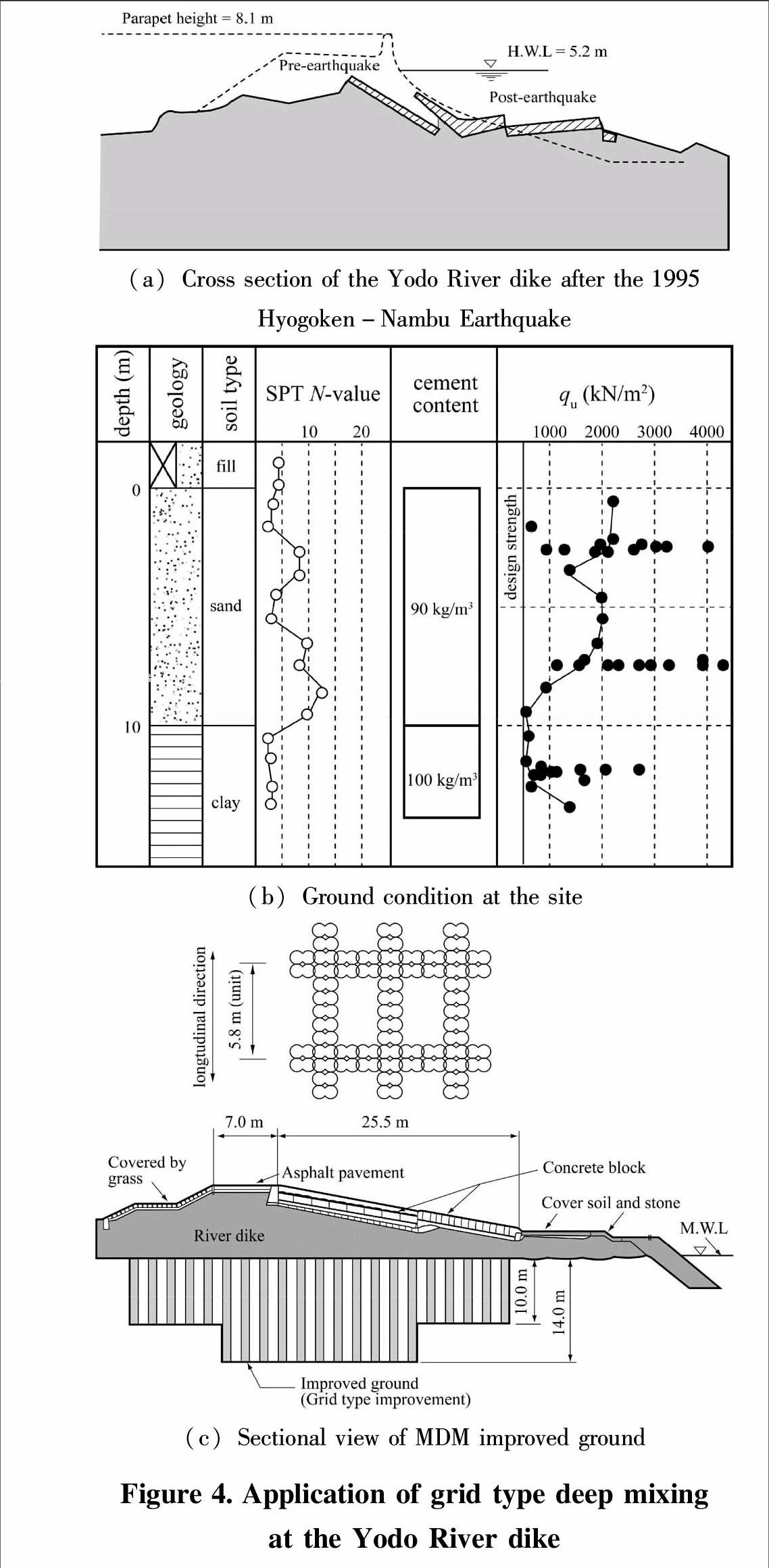
(b)Parking area in the buildingFigure 3Damage due to the earthquake14Application of the Grid Type DMM for EmbankmentYodo River flows from Lake Biwa to Osaka Bay through Osaka CityDue to the Hyogoken-Nambu Earthquake in January 1995,the river dike was heavily damaged for the length of 18 km because of slope failure due to ground liquefaction(Kamon,1996).A representative cross section of the damaged dike is shown in Figure 4a.The top portion of the river dike sank down about 3 mThe damaged dike had to be restored very quickly,because there was a risk of flooding during the rainy season which usually commenced in JuneThe ground condition at the site is shown in Figure 4b.The ground consisted of a sandy layer and a clayey layerAs the SPT N-value of the sandy layer was smaller than 10,the liquefaction might take place again in earthquake attack in the futureBecause there were many residential houses in the neighborhood along the river dike,it was necessary to avoid noise and vibratory problems during the constructionThis was one of the reasons why the deep mixing method was appliedThe cross section of the improved ground is shown in Figure 4c,where grid type improvement
(a)Cross section of the Yodo River dike after the 1995
Hyogoken-Nambu Earthquake
(b)Ground condition at the site
(c)Sectional view of MDM improved groundFigure 4Application of grid type deep mixing
at the Yodo River dike was applied to prevent the liquefaction of the ground and to improve the stability of river embankmentThe grid of the stabilized soil columns was about 5 m by 54 mThe design strength of the stabilized column,qu was 500 kPaAssuming the strength ratio of the field stabilized soil and laboratory stabilized soil,quf/qul was assumed to be 025 in the design,and 90 or 100 kg/m3 of blast furnace slag cement type B were mixed to achieve the design strength for the sandy layer and clay layer respectively
15Other applications of the Grid Type DMM
Soon after the aftermath of the 2011 Tohoku earthquake and tsunami,the Cement Deep Mixing(CDM)Association,the Dry Jet Mixing(DJM)Association and Chemical Grouting CoLtdconducted field surveys in the Tohoku and Kanto areas to investigate any deformation and damage in the deep mixing improved ground and the performance of the improved groundsThough few slight deformations were found in some grounds,as a whole no severe deformation and damage was found in the improved ground and superstructures even they were subjected to quite large seismic force(Kitazume,2012;Tokunaga et al,2015).Here,two applications in the field surveys are briefly introduced
151Road embankment
The road embankment at Soga,Chiba Prefecture,was improved by the grid type deep mixing method for liquefaction preventionThe original ground beneath the embankment contains large amount of fine sand to the depth of -7 m,which was anticipated to be highly liquefied due to earthquake motionThe improved ground has about 56 m in width,60 m in height,and the improvement area ratio is 50%,and whose unconfined compressive strength,qu is 200 kN/m2(Figure 5a).No damage was found in the embankment and the improved ground is shown in Figure 5b,even subjected to the seismic force of 50 upper in Japanese Magnitude-Shindo(seismic intensity scale).As contrast,Figure 5c shows heavy damage on road without improvement located in the neighborhood due to liquefaction
(a)Layout of ground improvement
(b)Road at improved area after earthquake
(c)Road at unimproved area after earthquakeFigure 5CDM improved ground at Soga,
Chiba Prefecture152River embankment
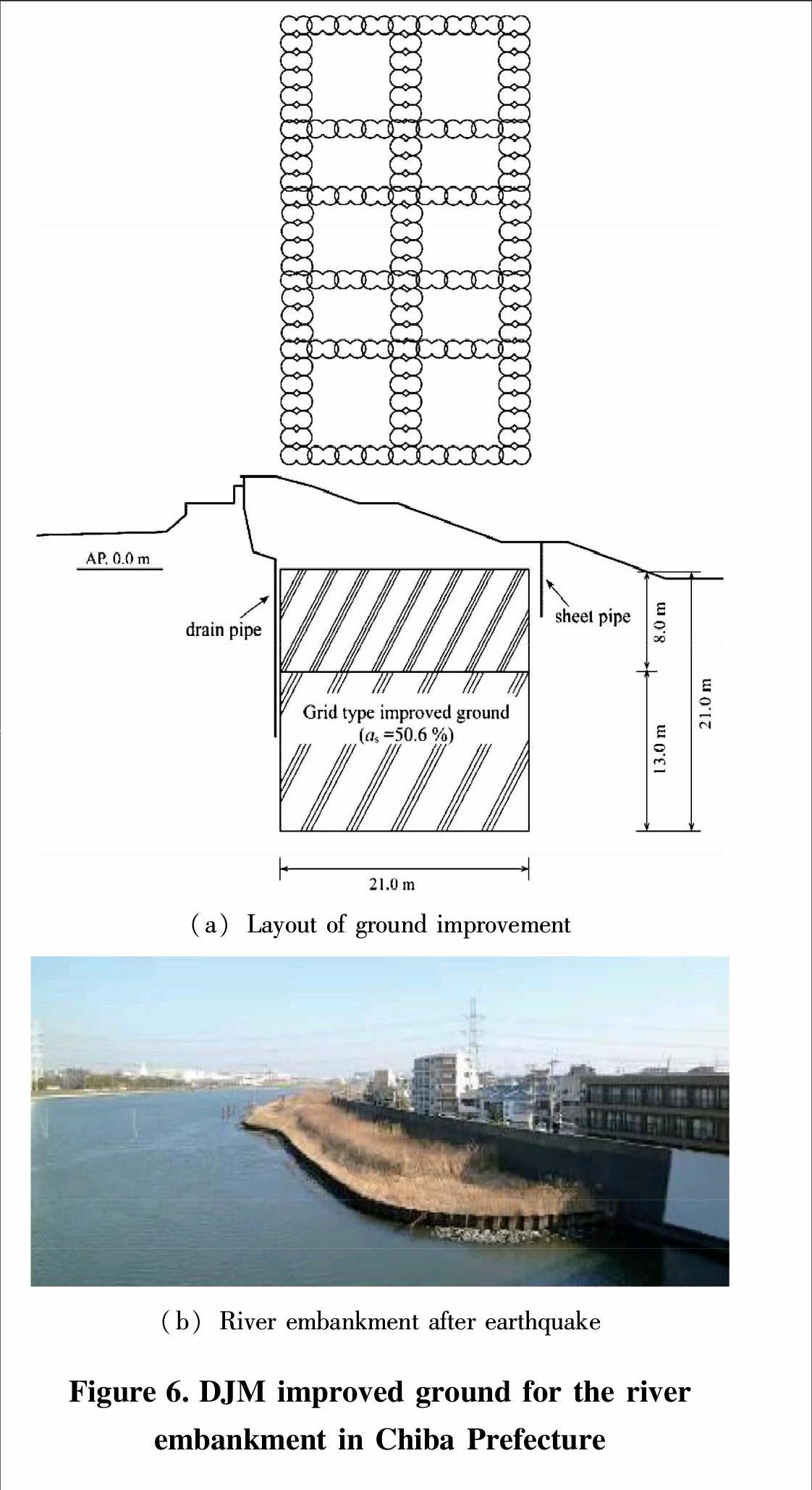
The foundation for the river embankment in Chiba Prefecture was improved by the grid type DM method as shown in Figure 6a,where the width and height of the improved ground were 210 m and 210 m respectively The improvement area ratio and the design
(a)Layout of ground improvement
(b)River embankment after earthquakeFigure 6DJM improved ground for the river
embankment in Chiba Prefecture strength were 506% and the design unconfined compressive strength,quck of 600 kN/m2 respectivelyNo damage was found in the embankment and the improved ground,as shown in Figure 6b.
2Concluding remarks
In this paper,some applications of Deep Mixing Method to earthquake disaster mitigation are briefly introducedThis paper at first emphasizes the importance of liquefaction mitigation to minimize earthquake disasterThe applications introduced in this paper clearly reveals the high applicability of the deep mixing method to earthquake disaster mitigationThe method has been applied successfully to various sites and improvement purposes in the past and expected to be developed further for more various sites and improvement purposes in the future
References:
KITAZUME M,TERASHI M.2013.The Deep Mixing Method.CRC Press[M].Abingdon:Taylor & Francis Group,434.
KITAZUME M.2012.Soil mixing performance in the 2011 Tohoku earthquake[J].The Magazine of the Deep Foundations Institute,77-78.
NAMIKAWA T,KOSEKI J,SUZUKI Y.2007.Finite element analysis of lattice-shaped ground improvement by cement-mixing for liquefaction mitigation[J].Soils and Foundations,47(3):559-576.
NODA S.1991.Waterfront development and liquefaction[J]Journal of the Japanese Society of Soil Mechanics and Foundation Engineering,‘Tsuchi-to-Kiso.Japanese Geotechnical Society,39(2):1-4.
SUZUKI Y,SAITOH S,ONIMARU S,et al.1996.Grid-shaped stabilized ground improved by deep cement mixing method against liquefaction for a building foundation[J].Journal of the Japanese Society of Soil Mechanics and Foundation Engineering,‘Tsuchi-to-Kiso,Japanese Geotechnical Society,44(3):46-48.
TOKIMATSU K,MIZUNO H,KAKURAI M.1996.Building damage associated with geotechnical problems[J].Soils and Foundations,52(5):219-234.
TOKUNAGA S,KITAZUME M,MORIKAWA Y,et al.2015.Performance of cement deep mixing method in 2011 Tohoku earthquake[J].Proc of the Deep Mixing 2015,1071-1080.
YAMAZAKI H.2000.Current and trend of ground improvement techniques for liquefaction prevention for port facilities(2)-Effectiveness and trend of techniques[J].Japan Society of Civil Engineers Magazine,Civil Engineering,85:60-62.

