Synthesis of a stroboscopic image from a hand-held camera sequence for a sports analysis
Kunihiro Hasegawa(),Hideo Saito
©The Author(s)2016.This article is published with open access at Springerlink.com
Synthesis of a stroboscopic image from a hand-held camera sequence for a sports analysis
Kunihiro Hasegawa1(),Hideo Saito1
©The Author(s)2016.This article is published with open access at Springerlink.com
DOI 10.1007/s41095-016-0053-5 Vol.2,No.3,September 2016,277–289
Thispaperpresentsa method for synthesizing a stroboscopic image of a moving sports player from a hand-held camera sequence.This method hasthree steps:synthesis ofbackground image, synthesis of stroboscopic image,and removal of player's shadow.In synthesis of background image step,all input frames masked a bounding box of the player are stitched together to generate a background image.The player is extracted by an HOG-based people detector. In synthesis of stroboscopic image step,the background image,the input frame,and a mask of the player synthesize a stroboscopic image.In removal of shadow step,we remove the player's shadow which negatively affects an analysis by using mean-shift.In our previous work,synthesis of background image has been timeconsuming.In this paper,by using the bounding box of the player detected by HOG and by subtracting the images for synthesizing a mask,computational speed and accuracy can be improved.These have contributed greatly to the improvement from the previous method. These are main improvements and novelty points from our previous method.In experiments,we confirmed the effectiveness of the proposed method,measured the player's speed and stride length,and made a footprint image.The image sequence was captured under a simple condition that no other people were in the background and the person controlling the video camera was standing still,such like a motion parallax was not occurred.In addition,we applied the synthesis method to various scenes to confirm its versatility.
sports vision; stroboscopic image; stitching;mask;synthesis
1 Introduction and motivation
Analyzing the performance of players has recently become popular in a variety of sports.Especially, using various technologies has become a major trend.A sensing technology is one of the examples. For example,the fatigue of athletic runners was evaluated using 12 wearable sensors to measure the displacement of the positions,angles,etc.,of each joint and of the waist[1].Data collected from sensors placed on a golf club and an athlete's body quantified a correctness of the performed golf swing[2].Changes in ventricular rates when running have been visualized with heartbeat sensors [3].Eskofier et al.[4]classified the motion of leg kicks during running by using an acceleration sensor.This classification could be used for fitting shoes,among other applications.Beetz et al.[5] proposed an analysing system for the football games using multiple sensors.
Using a video camera is also one solution for easy analysis.Various sports such as soccer[6],basketball [7,8],and American football[9]are already using computer vision technologies. For example,an off-side line was visualized by tracking of multiple players in the soccer[6].Lu et al.[7]and Perˇse et al.[8]proposed methods of identification,tracking, and motion analysis,etc.Atmosukarto et al.[9] proposed a method of recognition of a formation in American football.
Athletics is one of the targets of such analysis.For the analysis of athletic running,stride length and speed in each interval provide significant information for improving running performance.However,most conventional sensing technologies require special equipment such as a laser measuring instrument, multiple cameras,and/or motion sensors attached
to the runners,which is expensive.Moreover,the interest of amateur runners in such analyses has been growing,and for these users,easy and on-site analysis of running performance is needed.
In our previous work,we proposed measuring stride length and speed with a video camera by manually moving a hand-held camera,so that it captured the entire running performance(e.g., completing a 100-m sprint)with sufficient resolution [10]. In that method,we measured the runner's landing position by using the homography between an image coordinate system and the real world coordinate system to estimate stride length and speed.We also tried to use a stroboscopic image that captured changes of a runner's poses in motion for automated measurement of speed and stride length.In our synthesis of a stroboscopic image,an image including only the background was synthesized first and then the runner was extracted from each frame and overlaid on the background image.The image in which only the runner was extracted could be synthesized by taking the difference between the background image and the image in which the runner was previously overlaid. We felt that the problem of landing timing determination could be solved by analyzing the stroboscopic image, but the background image synthesis we used was based on the mean-shift of each pixel,which was computationally expensive.
In the present work,we propose a method for synthesizing the stroboscopic image of a sports player from a hand-held camera sequence based on a computationally efficient algorithm that generates a stitched background image by using the bounding box of the player detected by HOG(histograms of oriented gradients).This algorithm can also extract accurately a player by using a mask synthesized by subtracting images.These series of processing using masks to improve computational speed and accuracy are main improvement and novelty points from our previous method.We also analyzed various other sports using video camera images and found that it should be possible to use the stroboscopic image synthesized by our method for sports other than running.Therefore,we consider our use of the stroboscopic image for runners to be a representative example.
This paper is organized as follows: Section 2 describes several related works. Section 3 shows an environment and a condition of capturing video for proposed method.Section 4 describes a detail of each step of the algorithm.Section 5 discusses experiments and results to confirm a superiority. Section 6 concludes this paper.
2 Related works
As we are going to describe later,our proposed method can be divided into three parts:synthesis of background,synthesis of stroboscopic image,and removal of shadow.The first part also has a color alignment process and the second part is the same as foreground extraction and blending.Therefore, these four areas are related area.
Ebdelli et al. [11]have recently proposed an efficiently video inpainting method for synthesis of a background.They have used an energy function for object removal.There is a feature also of being less than the required number of images. In our method,we are taking advantage of the fact that a removal target is moving.By this fact,we can synthesis a background image using only an image transformation and a mask synthesis.
About color alignment,the method for reducing undesirable tonal fluctuations in video[12]and a color collection between multi-camera[13]have been proposed. Reference[12]designates one or more frames as anchors and executes a color alignment on basis of these frames. Reference[13]solves a difference in color between multiple cameras by an energy minimization.In this part,we utilize the process used in the based method[14],that is,a gain compensation and a multi-band blending.
Foreground extraction and blending in synthesis of background is one of the feature points of our proposed method. GrabCut[15]and an image cloning [16]are the representative methods of foreground extraction and blending.Our proposed method executes these processes by synthesizing and using a mask of a player.
Various methods have also been proposed about shadow removal.Guo et al.[17]have proposed a region based approach.They have used a relational graph of paired regions for detecting shadows. Miyazaki et al.[18]have proposed another method. This method has utilized MRF(Markov random field)and graph-cut for removal.In our method, we employ a method using mean-shift.
Further,there is a similarity with a motion object editing and representation in terms of output. For example,there are a generation of dynamic narratives from video[19],a production of objectlevel slow motion effects,etc.,[20]and scene-space video processing[21]. Features of the proposed method in comparison with these techniques are synthesis of a stroboscopic image and using a handheld camera.
3 Environment and conditions of capturing video
In this paper,we assume that video footage is captured using a hand-held camera operated by a person who controls the camera to capture the subject with a sufficient resolution in each frame,as shown in Fig.1.We assume the operator takes a video in a scene where the player is practicing in a running track,on an athletic ground,etc.It is assumed that no other people are in the background under this condition. The person controlling the video camera is standing still and catches the player on the screen in all frames.The video camera is held in the operator's own hand and is moved freely.
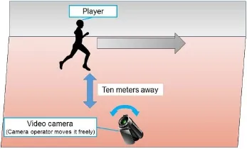
Fig.1 Image of capturing environment.
The operator stands dozens of meters away from the center of the track to capture the player in the entire moving scene by using zoom.There are no restrictions on the player's clothes and background except that the color of the background and clothes should not be exactly the same.
4 Proposed method
The goal of our previous method [10]was to synthesize a stroboscopic image for the automatic measurement of speed and stride length.In that method,a stitched image without a player has been synthesized and then the player has been overlaid on the stitched background image.As noted above, synthesizing the background image has been timeconsuming because mean-shift estimation[22,23] has been executed on every pixel of the image.This has been the main drawback of the method[10]. Therefore,we need a way of synthesizing the image in a short amount of time.
In the method we propose in the present work, in order to reduce computation time,we mask only a region in which the player exists in the image of each frame used for the stitched image synthesis. As a result,any images containing only background are synthesized because the region where the player exists is excluded from the stitched image synthesis. We improve other parts of our previous method[10], as well.Specifically,we add methods for overlaying the player and removing the player's shadow.Figure 2 shows a flowchart including these improvement points,with the differences between our previous and present methods highlighted.Red frames indicate that a step for processing content is different and green frames indicate an added or interchanged step. In the proposed method,we use the bounding box of a player to synthesize a background image.We
elaborate upon these points in Sections 4.1,4.2,and 4.3.
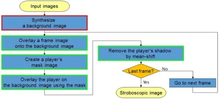
Fig.2 Flowchart of the proposed method.
4.1 Synthesis of background image
Here,we discuss the“synthesize a background image”process in Fig.2.A background image shown in Fig.3(c)is synthesized by stitching.As previously noted,we mask the area of the player as shown in Figs.3(a)and 3(b)to reduce the computation time.
The area of this mask is the bounding box of a player detected by HOG-SVM[24].The mask area of each frame is excluded in synthesizing a background image so that only a background pixel can be used for synthesizing the background image.HOG-SVM sometimes fails to detect the player in a motion sequence.Kalman filter[25]is applied for keeping track of the bounding box.
A stitching has two processing steps,calculating a homography and projection ofimages.The homography for this stitching uses feature points in each frame image.In order to extract feature points in complex environments such as the outdoors, SURF[26]is used as feature points and the stitch function of OpenCV is used for the synthesis,the same as in our previous method[10].
Our previous method[10]calculated each value of HSV for every pixel using mean-shift. In the proposed method,instead of mean-shift,we execute a stitching,as described above,which speeds up the synthesis of a background image.
4.2 Synthesis of stroboscopic image
Here,we describe the“overlay a frame image onto the background image”,“create a player's mask image”,and“overlay the player on the background image using the mask”processes in Fig.2.In this step,we use the other mask synthesized by a subtraction of images,an example of which is shown in Fig.3(e).This mask is the result of the“create a player's mask image”step and is used for overlaying the player on the background image in the“overlay the player on the background image using the mask”step.We elaborate upon these processes below.
Figure 3 except Fig.3(b)shows images for each step of this subsection.In the“overlay a frame image on the background image”step,an input image of each frame,Fig.3(a),is transformed and projected onto a coordinate system of the background image, Fig.3(c).This background image is the result of Section 4.1.The homography for the transformation and projection of Fig.3(a)is the same as in Section 4.1.As a result,a projected image,Fig.3(d),is synthesized.
In the“create a player's mask image”step,the projected image,Fig.3(d),and the background image,Fig.3(c),are utilized again.A player's mask image,Fig.3(e),is obtained by the subtraction and binarization of these two images.A part of the player area is occasionally lacking in the mask image if the color of the player's clothes is similar to that of the background,whereas we can compensate for this by a morphology process.Hence it is only a minor deficit.
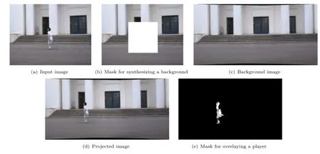
Fig.3 Images for background and stroboscopic image synthesis.
To overlay an area of player onto the background image,a transformed input image of each frame as Fig.3(a)is overlaid on the background image by
using a player's mask image,such as Fig.3(e).These steps are repeated to the last frame,at which point a stroboscopic image is synthesized.Of course,we change the background image to the stroboscopic image over making from the second frame.In our previous method,blending was needed to synthesize a stroboscopic image due to overlap of the bounding box of a player's area[10],and the difference between a player and a background might have become almost 0 in the worst case. In contrast,in our new method only the player is overlaid,so the player cannot disappear if the number of frames becomes enormous.
4.3 Removal of player's shadow
Here,we discuss the“remove the player's shadow by mean-shift”process in Fig.2.The stroboscopic image synthesized in Section 4.2 results in the player's shadow being visible under certain capturing conditions such as a sunny day. An example is shown in Fig.4,where some shadows remain in the red rectangles.In particular,shadows connected to the players expand the players'area.This negatively affects the calculation of the players' landing positions.
In order to remove these shadows,we use a synthesis method utilizing mean-shift,as explained in Ref.[27].This method estimates each background pixel by mean-shift estimation.Input of this method is the pixels of input images which are projected onto each pixel of the background image.The number of frames having shadow is smaller than the number of frames having the background in views where the player is moving.Therefore,mean-shift can remove the shadows.
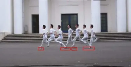
Fig.4 Stroboscopic image with shadow.
In mean-shift processing,the pixel value of each original image is assigned as the initial value.The bandwidth is 10.The kernel formula is Epanechnikov kernel the same as Ref.[27]. In addition,the weight for decision of the result is calculated for each candidate value.Finally,the value whose weight is the biggest is the background pixel value.In this calculation,the weight is the Gaussian to simplify the process.We select this removal area manually. The areas containing the shadow are quite small compared to the entire image.Processing time for this small area is a minor deficit.
5 Experiments
We performed five experiments.In the first experiment,we compared our proposed method with our previous method in each step,and in the second,we measured player's landing position, speed,and stride length using the stroboscopic image.In this experiment,we also visualized the player's footprints. In the third experiment,we compared the results of our method with those offourexistingmethods: GrabCut[15],the image cloning[16],autostitch[14],and the frame subtraction.Then,we applied the synthesis method to various sports scenes to confirm its versatility. In the last experiment,we did some experiments in some complicated scenes to investigate limits of the proposed method.We used Microsoft Visual Studio 2010 as the IDE,C++as the programming language, and OpenCV 2.4.11 as the image processing library for implementation.The PC we used had a 2.40 GHz CPU with 4 cores and 8.00 GB of memory.The HOG-SVM used to synthesize the mask was learned using about 20,000 player images for accurate detection. In some results,we show a subset of frames that have few intervals for visibility.
5.1 Synthesis of runner's stroboscopic image An input video for this experiment was captured by a hand-held camera. As described in Section 3,the camera was held in the operator's own hand to capture a runner in the center of the camera by manually tracking the runner.Figure 5 shows a part of the input image group used for the experiments. The size of the image was 640×480 pixels.
5.1.1 Synthesis of background image
Ourpreviousmethod [10]utilizing mean-shift for synthesizing a background image was timeconsuming.In our new method,we use the bounding box of a player detected by HOG to reduce the
computation time.

Fig.5 Example of input images.
A comparison of the processing time results is given in Table 1.We used only the three frames shown in Fig.5 for this experiment to compare to our previous experiment.The processing time for the previous and proposed methods was measured 10 times each.As indicated in the table,the proposed method utilizing a mask to reduce processing time is even faster than our previous method[10].
Figures 6(a)and 6(d)show the background image synthesized by our previous method[10]and the proposed method.As shown,the two images are almost equivalent.These results indicate that the image synthesized by our proposed method can be applied to the following process.
5.1.2 Synthesis of stroboscopic image
Our previous method[10]needed to blend overlaying player's areas with a background image,which resulted in the difference between the player and the background becoming almost 0 in the worst case. In the proposed method,we use a mask synthesizedby the input and background images to overlay the player on the background.

Table 1 Processing time of synthesizing a background image
Figures 6(b)and 6(e)compare the results of our previous[10]and proposed methods.Players were blended in the image of our previous method,as shown in Fig.6(e).In the previous method,it is believed to be as the player's legs clearly visible when the player is in contact with the ground.In practice, a timing at which the player does not ground,the background in the bounding box is shown in the same place. Thus,the player's legs become non clear because the background is also blended when the runner is grounding.In contrast,as shown in Fig. 6(b),the players in the stroboscopic image synthesized by the proposed method are not blended with the background.
In the result of the proposed method,the player's shadows are still not completely removed,as shown in Fig.6(b).However,the shadow can be removed in the next step,as mentioned above in Section 4.3,so we conclude that our proposed method can synthesize a stroboscopic image.
5.1.3 Removal of player's shadow
Under some capturing conditions,a stroboscopic image contains the player's shadows. To remove these shadows,we use a synthesis method utilizing mean-shift,as explained in Ref.[27].
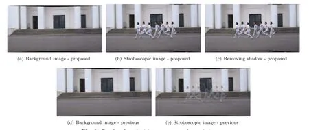
Fig.6 Results of synthesizing a runner stroboscopic image.
The result of removing the player's shadows from the image in Fig.6(b)is visible in Fig.6(c).A comparison of Figs.6(b)and 6(c)clearly shows that our proposed method can remove shadows.We did not make the result of the previous method because it did not have this step.In addition,the processing
time of this step was just 6.10s on average,which was barely 0.003%of the time it took to apply mean-shift to the entire image.These results demonstrate that our proposed method can remove shadows without consuming a lot of time.They also indicate that our proposed method can synthesize a stroboscopic image to measure the player's speed and stride length more easily than the previous method.
5.2 Measurement of player's landing position,speed,and stride length
Our goal of this system is measurement of the player's speed and stride length.In this experiment, first,we measured the player's landing positions necessary to measure speed and stride length.Then, we measured the player's speed and stride length.In the last,we visualized the player's footprints in this scene by using stroboscopic images.
Table 2 shows measuring error of each player's landing positions after 50 m running.Error of each step is shown in Fig.7.We measured the runner'slanding position by using a homography between an image coordinate system and the real world coordinate system.Input of positions of foot was manually.We made actual footprints as a ground truth by spiked shoes.Mini corns were known points for calculating the homography.In previous work [10],it was considered that an error of less than 0.3 m did not adversely affect the analysis.About 90% of these measuring errors are less than 0.3m in these results.Therefore,we think these results are almost useful.

Table 2 Error of measurement
Figures 8 and 9 show results of measurement using the above landing positions. In the analysis of speed and stride length,an important point is to understand a trend,such as a timing of maximum stride length,speed up,slow down,etc.We can catch information from these figures.Therefore,we can confirm our method is useful.In a few points, for example,Player C's timing of maximum stride length is different.The reason is considered to be due to the large measuring error at the 25th and 27th steps which are near 45 m,as you can be seen from Fig.7(c).Reduction of such a large error is a future study.
The result of the player's footprint visualization is shown in Fig.10.We can also represent results as intuitively by this means.
As another example,we used a video sequenceof an actual marathon race.Figure 11 shows a stroboscopic image and player's footprints.We took this video from a crowded walkway;therefore capturing range was shorter than other videos.The result of synthesis was successful.In this case,we used end of white lines on a road as known points. Ground truth could not be obtained in this situation, of course. Alternatively,we confirmed results of measuring using white lines as a guide.The results show that our proposed method can be used not only in one environment.

Fig.7 Measuring error.

Fig.8 Measurement of speed.

Fig.9 Measurement of stride length.
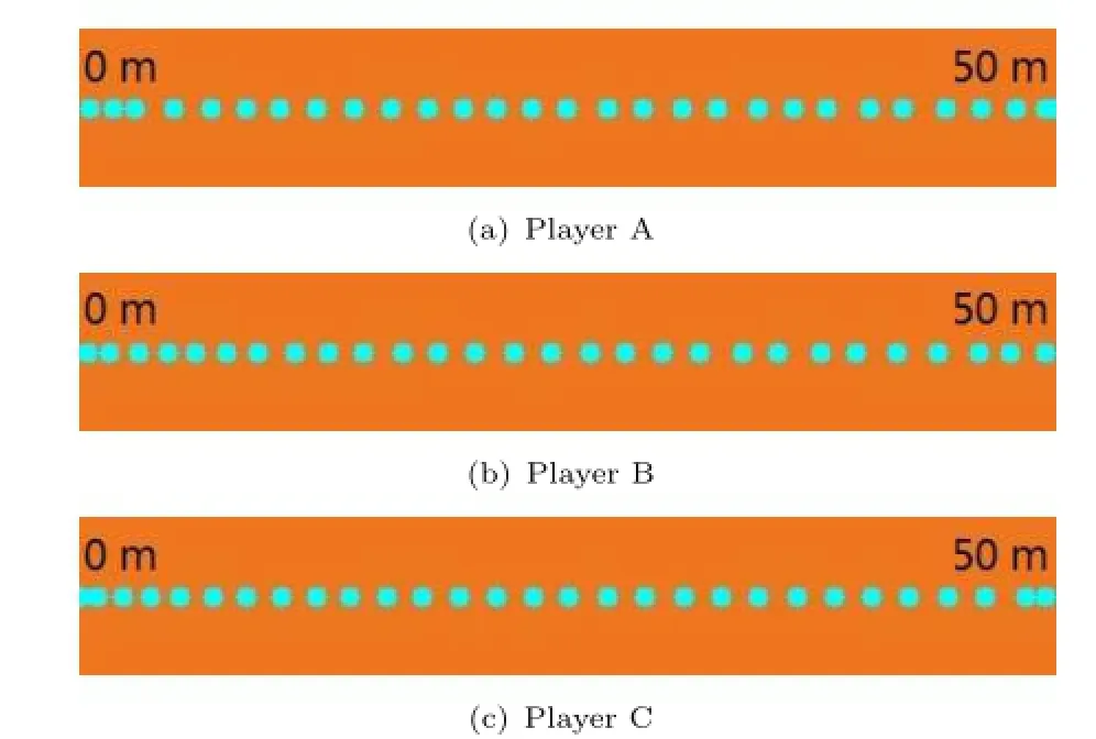
Fig.10 Visualization of player's footprints.
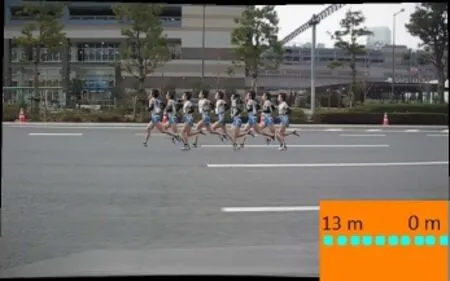
Fig.11 Result of an actual marathon race.
5.3 Comparison with existing methods
First,we compared the performance of foreground extraction and image blending in our proposed method with GrabCut[15]and the image cloning [16].
Figure 12 shows the results of player extraction by our method and GrabCut.We input a target area of GrabCut manually.The green frame in each image is a target area.Our method could successfully extract a player clearly in all scenes,whereas GrabCut could not extract a player in some scenes. Especially, the part of foot or lower body was often lack.We estimate that a reason of this problem is a difference of color.For example,a color of a cloth is usually different from the upper and lower body or shoes. This difference makes an edge inside of a player area. GrabCut cannot extract a player clearly by this edge.
The images including these defects are not suitable for measurement of speed and stride length or checking forms because everyone cannot recognize a player clearly.In the case of using a cloth having a complex pattern such as figure skating(the third from the right in Fig.12),GrabCut could not extract anything. Our proposed method subtracted the player region and the background area.Therefore, it does not occur the problem such as GrabCut.
Figure 13 shows the result of the image cloning.In this figure,we blended only two frames by the image cloning.We can find that the players blended with a background in some scenes.Since synthesizing a stroboscopic image by repeating the same process, we can understand it is difficult to synthesize a stroboscopic image using the image cloning from this result.This is because that the extracted image for cloning had a part of a background.The player in the other frame was blended with this background.To solve this problem,we need to extract only a player's
area.Our proposed method executes the equivalent of it such as Fig.6(b).

Fig.12 Comparison with GrabCut(top:proposed method,bottom:GrabCut).

Fig.13 Results of the image cloning.
Second,autostitch and frame subtraction were the targets to compare with synthesis of a stroboscopic image.Figure 14 shows the result of these methods. Autostitch does not concern itself with whether an image contains a person or not;therefore Fig.14(a) has people in only a limited number of frames. The method using frame subtraction is originally for a fixed camera.As shown in Fig.14(b),this method did not work on scenes captured by handheld camera.
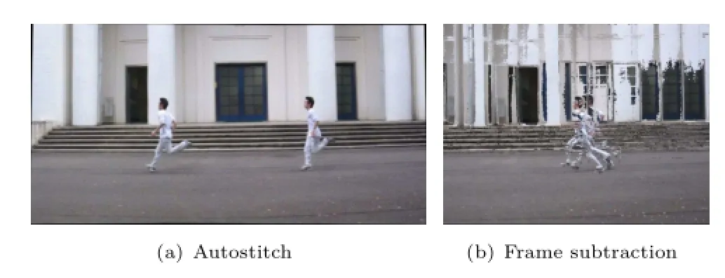
Fig.14 Results of existing methods.
Figure 15(a)shows the synthesis results of our proposed method in another scene in order to show that this method can be used in various environments.There are runners in all frames,the same as in Fig.6(c).The results of the two existing methods are shown in Figs.15(b)and 15(c).They are the same as the results in Figs.14(a)and 14(b). These results clearly demonstrate the superiority of our proposed method.
5.4 Application to other scenes
As stated previously,we executed our method on other scenes,especially other sports in this experimentto confirm itsversatility.Walking, downhill skiing,figure skating,and speed skating were the targets of this experiment.The walking scene was captured by us,the same as in other experiments.The other videos were captured by others.The results of this second experiment show that our proposed method can be used for various purposes such as checking player's form. This is because we have assumed the use of the image in addition to measuring.

Fig.15 Results of stroboscopic image synthesis in another scene.

Fig.16 Examples of application to walking.

Fig.17 Examples of application to downhill skiing.

Fig.18 Examples of application to figure skating.

Fig.19 Examples of application to speed skating.
The results are shown in Figs.16,17,18,and 19. These results are the same as those in Figs.6(c),11, 14,and 15.Our proposed method overlaid players onto a background image;therefore players appear in all frames in Figs.16(a),17(a),18(a),and 19(a). We made the footprints on walking scene.Skiing and skating do not have a concept of footprints,so we did not make the footprints on these scenes.Autostitch cannot always synthesize a stroboscopic image due to its not being able to extract the player from each frame.Figures 16(b),17(b),18(b),and 19(b) contain players in only part of the frames as a result. The method using the frame subtraction does not consider that the camera moves freely,so it cannot
synthesize a stitched image and a stroboscopic image from a non-fixed camera sequence,as evident in Figs. 16(c),17(c),18(c),and 19(c).
These resultsconfirm the versatility ofour proposed method.If we change the object detection method,we can detect targets other than people, such as cars.
5.5 Limitations
In the last experiment,we investigated limitations of our proposed method.First,we used a rollingshutter camera.A rolling-shutter camera is a weak to shoot a moving object.It is necessary to confirm whether or not our proposed method can use a smart phone which usually has a rolling-shutter camera.
We synthesized a stroboscopic image using a rolling-shutter camera and targeting a runner.The result in running scene is shown in Fig.20.We can find that a synthesis of stroboscopic image using rolling-shutter camera by our proposed method was successfully in this case,such that a runner was a target.To synthesize a stroboscopic image using a rolling-shutter camera,it is necessary that all the pixels are captured at the same timing.In this scene, a video camera operator does not need to move a camera fast because the runner's speed is not so fast. Therefore,we estimate that the above condition was satisfied.Of course,if a target object moves faster, such as a car or a bike,the result may not be the same because it is difficult to satisfy this condition.
Second,we used the image sequence including a camera shake.A camera shake often occurs in using a hand-held camera.Figure 21 is the input image sequence of this experiment.As a result,our proposed method could not synthesize a stroboscopic image.We assume that our proposed method is used under a simple condition,as we described in Section 3. Therefore,complex conditions like this scene occurred a motion parallax or a complex background were out of scope.It is one of our future works to be able to use our proposed method under these conditions.
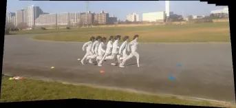
Fig.20 Result using rolling-shutter camera.
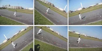
Fig.21 Input images in shaking scene.
As other candidate of a limitation,we examined the case that the colors between a video frame and the synthesized background are not perfectly matched. Because of an illumination variation, etc.,in shooting,it is the color sometimes different between an input image and a background image. This difference makes noises in a mask image.In player extraction,these noises make an extra area of non-player.If this area exists near the player, it may connect with the player in the morphology processing.We execute the morphology processing so that this connection is not occurred.Of course,it is ideal that this noise does not occur.To realize this ideal condition,we should execute another processing in making a mask.For example,a slight difference in color is regarded as the same color or we perform a color reduction processing to match color easily.
6 Conclusions
In thispaper,wehaveproposedthemethod of synthesizing a stroboscopic image to enable a measurement of a player's speed and stride length in an automated system.In particular,we have sped up the processing of background image synthesis by utilizing the bounding box of a player detected by HOG.We have also improved the overlaying of a player using mask and the removal of shadows.We have demonstrated the superiority of our proposed method through experiments and confirmed that it can be used in various scenes.
If we do not satisfy the condition listed in Section 3,our method cannot work well.For example,if the colors of the background and clothes are exactly the same,we cannot synthesize a stroboscopic image.
The conditions described in Section 5.5 are also representative examples.To solve this problem is one of our future works.
Our proposed method has a few of manual steps. For example,the morphology process in the synthesis stroboscopic image step and the selection of removal area in the removal of a shadow are manual.In addition to a measurement accuracy improvement of landing position,our future work will be to improve these steps for the realization of full automation.For example,in the shadow removal step,if the area of the shadow can be extracted automatically,the problem goes away.Therefore,tracking the shadow area with some sort of tracking method is one of the solutions. We will examine various solution candidates in our future work.
Acknowledgements
This work has been supported in part by JSPS Grant-in-Aid for Scientific Research(S)24220004, and JST CREST“Intelligent Information Processing Systems Creating Co-Experience Knowledge and Wisdom with Human–Machine Harmonious Collaboration”.
[1]Strohrmann,C.;Harms,H.;Kappeler-Setz,C.; Troster,G.Monitoring kinematic changeswith fatigue in running using body-worn sensors. IEEE Transactions on Information Technology in Biomedicine Vol.16,No.5,983–990,2012.
[2]Ghasemzadeh,H.;Loseu,V.;Guenterberg,E.;Jafari, R.Sport training using body sensor networks:A statistical approach to measure wrist rotation for golf swing.In:Proceedings of the 4th International Conference on Body Area Networks,Article No.2, 2009.
[3]Oliveira,G.;Comba,J.;Torchelsen,R.;Padilha, M.;Silva,C.Visualizing running races through the multivariate time-seriesofmultiple runners. In:Proceedings of XXVI Conference on Graphics, Patterns and Images,99–106,2013.
[4]Eskofier,B.M.;Musho,E.;Schlarb,H.Pattern classification of foot strike type using body worn accelerometers.In:Proceedings of IEEE International Conference on Body Sensor Networks,1–4,2013.
[5]Beetz,M.;Kirchlechner,B.;Lames,M.Computerized real-time analysis of football games.IEEE Pervasive Computing Vol.4,No.3,33–39,2005.
[6]Hamid,R.;Kumar,R.K.;Grundmann,M.;Kim,K.; Essa,I.;Hodgins,J.Player localization using multiple static cameras for sports visualization.In:Proceedings of IEEE Conference on Computer Vision and Pattern Recognition,731–738,2010.
[7]Lu,W.-L.;Ting,J.-A.;Little,J.J.;Murphy,K.P. Learning to track and identify players from broadcast sports video.IEEE Transactions on Pattern Analysis and Machine Intelligence Vol.35,No.7,1704–1716, 2013.
[8]Perˇse,M.;Kristan,M.;Kovaˇciˇc S.;Vuˇckoviˇc,G.;Perˇs, J.A trajectory-based analysis of coordinated team activity in a basketball game.Computer Vision and Image Understanding Vol.113,No.5,612–621,2009.
[9]Atmosukarto, I.; Ghanem, B.; Ahuja, S.; Muthuswamy,K.;Ahuja,N.Automatic recognition of offensive team formation in American football plays. In:Proceedings of IEEE Conference on Computer Vision and Pattern Recognition Workshops,991–998, 2013.
[10]Hasegawa,K.;Saito,H.Auto-generation of runner's stroboscopic image and measuring landing points using a handheld camera.In:Proceedings of the 16th Irish Machine Vision and Image Processing,169–174,2014.
[11]Ebdelli,M.;Meur,O.L.;Guillemot,C.Video inpainting with short-term windows: Application toobjectremovaland errorconcealment.IEEE Transactions on Image Processing Vol.24,No.10, 3034–3047,2015.
[12]Farbman,Z.;Lischinski,D.Tonal stabilization of video.ACM Transactions on Graphics Vol.30,No.4, Article No.89,2011.
[13]Lu,S.-P.;Ceulemans,B.;Munteanu,A.;Schelkens, P.Spatio-temporally consistent color and structure optimization for multiview video color correction. IEEE Transactions on Multimedia Vol.17,No.5,577–590,2015.
[14]Brown,M.;Lowe,D.G.Automaticpanoramic image stitching using invariant features.International Journal of Computer Vision Vol.74,No.1,59–73, 2007.
[15]Rother,C.;Kolmogorov,V.;Blake,A.“GrabCut”: Interactive foreground extraction using iterated graph cuts.ACM Transactions on Graphics Vol.23,No.3, 309–314,2004.
[16]Farbman,Z.;Hoffer,G.;Lipman,Y.;Cohen-Or,D.; Lischinsk,D.Coordinates for instant image cloning. ACM Transactions on Graphics Vol.28,No.3,Article No.67,2009.
[17]Guo,R.;Dai,Q.;Hoiem,D.Single-image shadow detection and removalusing paired regions.In: Proceedings of IEEE Conference on Computer Vision and Pattern Recognition,2033–2040,2011.
[18]Miyazaki,D.;Matsushita,Y.;Ikeuchi,K.Interactive shadow removal from a single image using hierarchical graph cut.In:Lecture Notes in Computer Science, Vol.5994.Zha,H.;Taniguchi,R.;Maybank,S.Eds. Springer Berlin Heidelberg,234–245,2009.
[19]Correa,C.D.;Ma,K.-L.Dynamic video narratives. ACM Transactions on Graphics Vol.29,No.4,Article
No.88,2010.
[20]Lu,S.-P.;Zhang,S.-H.;Wei,J.;Hu,S.-M.;Martin, R.R.Timeline editing of objects in video.IEEE Transactions on Visualization and Computer Graphics Vol.19,No.7,1218–1227,2013.
[21]Klose,F.;Wang,O.;Bazin,J.-C.;Magnor,M.; Sorkine-Hornung,A.Samplingbased scene-space video processing.ACM Transactions on Graphics Vol. 34,No.4,Article No.67,2015.
[22]Fukunaga,K.;Hostetler,L.The estimation of the gradient of a density function,with applications in pattern recognition. IEEE Transactions on Information Theory Vol.21,No.1,32–40,1975.
[23]Comaniciu,D.;Meer,P.Mean shift: A robust approach toward feature space analysis.IEEE Transactions on Pattern Analysis and Machine Intelligence Vol.24,No.5,603–619,2002.
[24]Dalal,N.;Triggs,B.Histograms of oriented gradients forhuman detection.In: ProceedingsofIEEE Computer Society Conference on Computer Vision and Pattern Recognition,Vol.1,886–893,2005.
[25]Kalman,R.E.A new approach to linear filtering and prediction problems.Journal of Basic Engineering Vol.82,No.1,35–45,1960.
[26]Bay,H.;Ess,A.;Tuytelaars,T.;Gool,L.V.Speededup robust features(SURF).Computer Vision and Image Understanding Vol.110,No.3,346–359,2008.
[27]Cho,S.-H.;Kang,H.-B.Panoramic background generation using mean-shift in moving camera environment.In: Proceedings of the International Conference on Image Processing,Computer Vision and Pattern Recognition,829–835,2011.

Kunihiro Hasegawa received his B.E. and M.E.degrees in information and computer science from Keio University, Japan,in 2007 and 2009,respectively. He joined Canon Inc.in 2009. Since 2014,he has been in Ph.D.course ofscience and technology atKeio University,Japan.His research interests include sports vision, augmented reality, document processing,and computer vision.

Hideo Saito received his Ph.D.degree in electricalengineering from Keio University,Japan,in 1992.Since then, he has been on the Faculty of Science and Technology,Keio University.From 1997 to 1999,he had joined into Virtualized Reality Project in the RoboticsInstitute, Carnegie Mellon University as a visiting researcher.Since 2006,he has been a full professor of Department of Information and Computer Science,Keio University.His recent activities for academic conferences include a program chair of ACCV2014,a general chair of ISMAR2015,and a program chair of ISMAR2016. His research interests include computer vision and pattern recognition,and their applications to augmented reality, virtual reality,and human robot interaction.
Open Access The articles published in this journal are distributed under the terms of the Creative Commons Attribution 4.0 International License(http:// creativecommons.org/licenses/by/4.0/), which permits unrestricted use,distribution,and reproduction in any medium,provided you give appropriate credit to the original author(s)and the source,provide a link to the Creative Commons license,and indicate if changes were made.
Other papers from this open access journal are available free of charge from http://www.springer.com/journal/41095. To submit a manuscript,please go to https://www. editorialmanager.com/cvmj.
1Keio University,Yokohama,223-8522,Japan.E-mail: K.Hasegawa,hiro@hvrl.ics.keio.ac.jp(); H.Saito, saito@hvrl.ics.keio.ac.jp.
Manuscript received:2016-01-22;accepted:2016-04-10
 Computational Visual Media2016年3期
- Computational Visual Media的其它文章
- An evaluation of moving shadow detection techniques
- Analyzing surface sampling patterns using the localized pair correlation function
- Skeleton-based canonical forms for non-rigid 3D shape retrieval
- Parallelized deformable part models with effective hypothesis pruning
- Discriminative subgraphs for discovering family photos
- Removingmixed noiseinlow ranktexturesbyconvex optimization
