Heat transfer ofnano fluidics in hydrophilic pores:Insights from molecular dynamics simulations☆
Mingjie Wei,Yang Song,Yong Wang*
State Key Laboratory ofMaterials-Oriented ChemicalEngineering,Jiangsu NationalSynergetic Innovation Center for Advanced Materials and College ofChemicalEngineering,Nanjing Tech University,Nanjing 210009,China
1.Introduction
Fluid flows in nanopores have attracted considerable attention for years[1],since it is related with severalacademic and industrialtopics,such as rock erosion,ionic channel and membrane separation.For example,in the field ofmembrane separation,the mass transport in con finement is mostconcerned,so that mostworks are focused on fabricating new materials[2,3].Recent findings of fast water transport in carbon-based materials[2,4–6]encourage the researchers to investigate the mechanism ofmass transport ofa fluid flow in nano-con finements,but it is quite dif ficult to study the fluid flow in nano-scale via direct experimentalobservations.
Although there are several experimental methods to observe the molecular properties of fluid,such as neutron scattering,scanning tunnel microscopy and atomic force microscopy,none of them works in the condition ofa flow state.In investigating the molecular mechanism of fluid in nanopores,molecular simulations exhibitthe advantage[7].To study molecular properties of fluid atthe flow state,a non-equilibrium molecular dynamics(NEMD)simulation is required,through which not only molecular properties can be calculated but also the macroscopic properties such as velocity pro file and flux of the flow are obtained at the same time[8–10].Thus there are some NEMD works published recently trying to explore why there being fast water transport in carbon nanotubes[9,11,12].
Compared to mass transport,the heattransportofnano fluidicsisrarely concerned.Mostresearchers believe thatthe heatcaused by viscosities(within fluid molecules)and frictions(between fluids and solid walls)is very limited as the scale ofnanopores being small,so there willbe hardly any heat generated in the nano fluidics.Moreover,it is generally considered thatadding smallparticles into a fluid is one of the methods to increase the rate ofheat transfer by convection between the fluid and the surface[13,14].However,the exact cause of the enhancement ofheat transfer in nano fluids is stillnot fully understood[15–17].Since the concept ofcontinuum of fluid is not applicable any more in the nano-scale,we try to find outhow heat conducting in nano fluidics by NEMDsimulations in this work.We build up the slitnanopores ofSiO2and TiO2then let the single phase water flow through those channels via NEMD simulations.By analyzing the outputfrom simulations we explore the heatconduct ofnano fluidics in hydrophilic channels.
2.Simulation Details
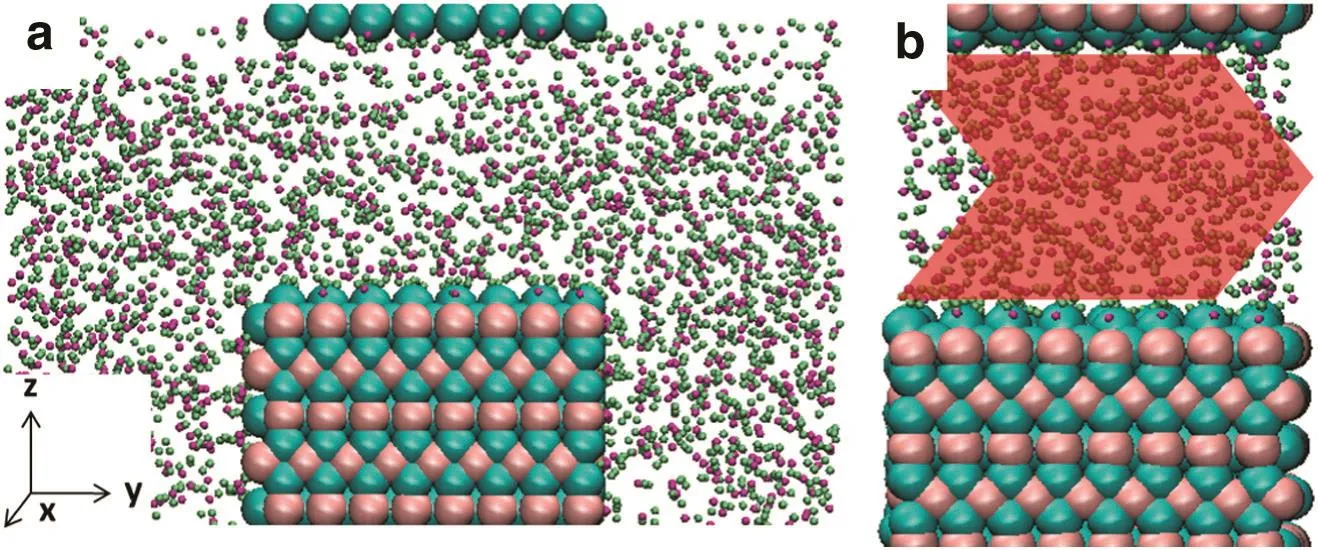
Fig.1.Snapshot for simulation box(2.0 nm rutile slit shown only):pink,Ti;cyan,O of rutile;purple,O of water;lime,H.Red,green and blue axes represent x,y and z directions,respectively.(a)The initialsnapshot of1 ns NPT simulation to obtain precise water density in the slit,3D periodicalboundary condition used to form the slits.(b)The initialsnapshot of10 ns NEMD simulations with obtained water density in slits.The red arrow indicated the externalforce.
Similarto ourprevious work[18,19],the slitnanopores ofrutile TiO2and quartz SiO2were built as shown in Fig.1.The area exposed to fluid molecules are 2.752×1.965 nm2and 2.600×2.367 nm2for quartz and rutile,and the slit widths were set to be 2.0 and 2.2 nm for rutile and quartz models,respectively.SPC/E water was chosen to act as fluid in the nanopores,since SPC/E model was among the best of the nonpolarizable models for water as it reproduces the vapor–liquid phase envelope as wellas other structuraland transportproperties atambient conditions[20,21].The interactions ofwallatoms and those between fluid and walls were described in the work of Bandura and Kubicki[22]for the rutile cases and by ClayFF[23]for quartz those.
Before a simulation ofwater flow in slit nanopores,the precise density of water in slits is crucial.For this reason,the isothermal-isobaric(NPT)ensemble is needed to determine the density of water in the nanopores.In order to save the computing time,only one slab ofrutile or quartz was placed in each simulation box,and the slit pore could be formed by the three dimensional periodic boundary condition.If the typicalthree-dimensionalNPT ensemble algorithmwas applied in alldirections,the slitwidth could notbe preserved.To solve this problem,we applied barostat in one direction only(y direction in this work)while placing two water reservoirs outside the slits in y direction(as shown in Fig.1a).After 1 nanosecond(ns)simulation,the average density of waterin the slitswas calculated.Itis noted thatthe pressure in NPT simulations was set to 100 bars to avoid the appearance ofnano bubbles.
After water molecules in the nanopores being initialized,10 ns NEMD simulations were performed without the reservoirs(i.e.,restoring periodic boundary conditions in allthree directions,as shown in Fig.1b).A series of externalforce was added to water molecules directly to maintain the flow state[9,24,25],which are 0.2 to 1.0 in atomic unit(kJ·mol-1·nm-1).Some atoms in the slabs were frozen to keep the slitwidths unchanged and to preventthe slab ofwalls from moving with the flow during simulations running and the thermostat was coupled with the other atoms ofwalls at300 K.There is no thermostat directly coupled with water molecules because the thermostat willdisturb the free motion of water molecules three dimensionally[26,27],so the microcanonical(NVE)ensemble was applied to water molecules[9,28].Allsimulations were carried outfortotally 10 ns with time step of 1.0 fs by LAMMPS package[29].Generally,a steady state of flow reached within 100 ps,so allthe data collected below came from the last 9 ns simulations for accuracy.
3.Results and Discussions
As introduced in the lastsection,the nanopores builtin this work are slitchannels,so thatthe velocity pro file could be described,according to the theory oftransport phenomenon,as[30]:

whereρandμare the density and viscosity of fluids,respectively,and g is the gravity worked on the fluids,which came from the externalforce we added to each atoms in simulations.This equation is the formatof Hagen–Poiseuille equation for steady flow between two parallelplates,which indicated that the velocity pro file should present parabolic(shown in Fig.2).
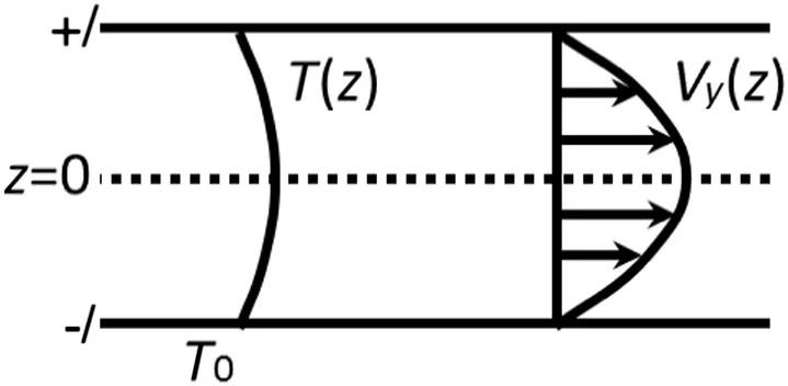
Fig.2.The sketch of Hagen–Poiseuille equation for steady flow between two parallel plates.T(z)and Vy(z)are temperature and velocity pro files of fluid flows,respectively.T0 indicates the temperature of wallatoms and the slit width is 2 l.
To calculate the velocity pro file ofwater molecules,the slit channel was divided into 200 bins,then the velocities ofmolecules in each bin were averaged throughout 1 ns.By plotting the average velocities of each bin in one figure,we got the velocity pro files for each case(shown in Fig.3).Actually,the velocity pro file in Fig.3 was further averaged by 9 ns(from 2 to 10 ns of each simulation)and the error bar gave the deviation ofeach averaged velocity from every 1 ns.
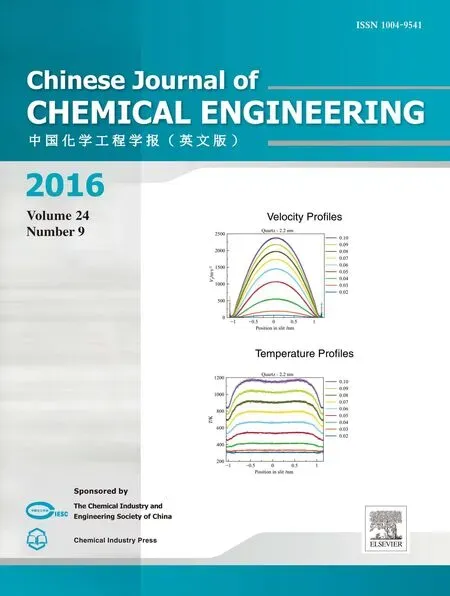
From Fig.3,it was found that all velocity pro files of water molecules were indeed parabolic,as predicted by the Eq.(1)above.Similar results can be found in the work of simpli fied atom systems[31,32].The maximum velocity was enhanced as expected while the external force increased.Moreover,in the same condition of external force,the maximum velocities of water(listed in Table 1)in quartz channel(2.2 nm wide)was higher than those in rutile channel(2.0 nm wide),which is corresponding to the prediction from HP equation as larger pore size exhibits higher velocities.
It is noticeable that the velocities of water molecules were much larger than those in natural or industrialprocesses.In this work,we tried to figure out how heat conducts,so we let the system generate more heat by adding much larger force on water molecules,which resulted in higher flow velocities.Although the velocities were higher than normalthose,the steady state could be maintained,as the deviation of averaged velocities(error bar in Fig.3)was small.
It is also obvious that the flow velocities of water molecules near solid walls reached zero,indicating the non-slip condition.The error bar increased in this area due to the low density of water,as fewer water molecules could be counted in to calculate the average velocities.
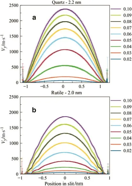
Fig.3.Velocity pro files ofwater molecules for the cases ofquartz(a)and rutile(b).
Afterthe velocity pro filesforeach case being con firmed,the temperature pro files were then calculated,since the speed ofwater molecules in flow direction(y)including the flow velocity,which should be excluded to calculate the temperature ofwater.The temperature pro file was calculated based on the speed of each water molecules in bins as described above and the processing ofaveraging was the same as the one to calculate the velocity pro file.
From the traditionaltheory oftransportphenomenon,the temperature pro file should be parabolic as well,

where kfis heat conductivity ofwater.But in Fig.4,the temperature pro files were out of our expectation.In the central part of the slit nanopores,there were rarely temperature gradient.Outside there,the temperature of water signi ficantly dropped,but not to the one set to the wallatoms(300 K).

Table 1 Maximum of the velocity pro file in Fig.2

Fig.4.Temperature pro files ofwater molecules for the cases ofquartz(a)and rutile(b).
There was parabolic velocity pro file for each case(shown in Fig.3),which indicated that viscous heat was generated in the fluid including the one in centralpart.However,in that part,we did not find evident temperature gradient.It is most possible that the heat was conducted without temperature gradient,probably due to the molecular motion[33].Outside the centralpart,there was an obvious temperature drop,which indicated thatthe heatconducted by only molecularmotion is insuf ficient.Actually,the viscous heatgenerated in centralpartwas small in amount due to the low velocity gradient,so the heat could easily transfer by the molecular motion.When this heat transferred outside the centralpart,it encountered more heat which is generated by the high velocity gradient.Hence,the accumulated heatneed to be conducted by another effective way which is temperature gradient.
There was another interesting finding in Fig.4,which was the discontinuous temperature drop between fluid and the wall,which was also found by Kim,Aliand Cagin[34].The temperature of fluid drops dramatically near walls,but the temperature of the layer close to walls was higher than the temperature ofwallatoms,probably due to the well-known Kapitza Resistance[32].
It is necessary to find out how this phenomenon occurred,and therefore we turned to the energy balance of our simulations.Once a fluid flow reaches the steady state,the viscous heat generated willbe fully conducted into wallsince no heat willaccumulate in the system.Hence,we built up the energy balance as:

where W was the work of external forces added on water atoms equaling and Q was the heat transfer from fluid to the wall,while t indicated the time.The work of externalforces per unit time could be described as:

By substituting Vy(z)with Eq.(1),we could get

where Lxand Lyis the size of quartz or rutile slabs.The heat transfer was estimated by the heat transfer in solid phase,which is

where D indicates the distance between fluid and walls,and kfwis the conductive coef ficients between fluid and walls.ΔT represents T fluid-T wall.
Combining Eqs.(3),(5)to(6),we could find

From Eq.(7),there seemsa linearrelationship betweenΔT and g2.To make sure that linear relationship,theΔT vs.g2was plotted(shown in Fig.5).Itis clear thatalldata stayed closely to the fitting line(dashed),especially forthe large g cases.The probably reason for departure ofdata from the fitting line is the variety of k andμ,since they are dependent with the temperature of fluid.
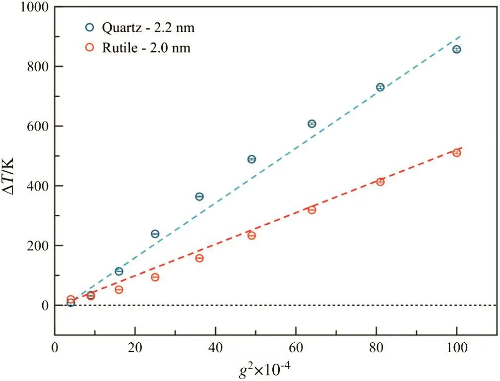
Fig.5.The relationship between the temperature differences between fluids and walls and the square of gravity.Circles represent the data from simulations,while the dashed lines are fitting results.
The slopes of dashed lines for two kinds of walls were different,which were 9.037 and 4.956 for quartz and rutile,respectively.From Eq.(7),such difference came from not only the slit width but also the kfw,the heat conductivity between fluid and walls,which is dependent of the microstructure ofinterfaces[35].
Although we could not easily obtain the exactrelationship between ΔT and g2,Eq.(7)disclose a factthat,for mostnaturaland industrialprocesses in which g is no more than 1.0×10¹³m·s-2(equals around 30 MPa pressure drop for nano fluidics),1 K ofΔT is suf ficientto conduct heatfrom fluid to walls.Moreover,when the externalforce gets large,the fluid willrise in temperature to enhance the heat conduct between fluid and walls,so as to maintain the whole system to be steady state.
4.Conclusions
The heat transfer of nano fluidics con fined in hydrophilic channels was investigated by NEMD simulations and it was found that the heat was conducted without temperature gradient in the central part of nanopores,which indicated thatthe heatconductivity caused by molecular thermalmovement(Brownian motion)of fluids is suf ficient for conducting the viscous heat in the width of around 1 nm.The heat transfer between fluids and walls was enhanced by increasing temperature of fluids itself so as to enlarge the temperature gradient between fluids and walls.However,when the fluid-walltemperature difference reached 1 K,it is ef ficient to transfer the heat from fluids to walls,for the lower flow velocity cases where mostof the application ofindustries and naturalprocesses is located.Hence,there is no need to concern the heattransfer of fluid in nanopores,especially in hydrophilic channels.It should be mentioned that the heat transfer of fluids in hydrophobic nanopores needs to be reconsidered thoroughly because the mechanism of mass transport will no longer be described by the traditional transport theories.
Nomenclature

[1]L.Bocquet,E.Charlaix,Nano fluidics,from bulk to interfaces,Chem.Soc.Rev.39(2010)1073–1095.
[2]R.Das,M.E.Ali,S.B.A.Hamid,S.Ramakrishna,Z.Z.Chowdhury,Carbon nanotube membranes for waterpuri fication:Abrightfuture in waterdesalination,Desalination 336(2014)97–109.
[3]S.P.Surwade,S.N.Smirnov,I.V.Vlassiouk,R.R.Unocic,G.M.Veith,S.Dai,S.M.Mahurin,Water desalination using nanoporous single-layer graphene,Nat.Nanotechnol.10(2015)459–464.
[4]J.K.Holt,H.G.Park,Y.Wang,M.Stadermann,A.B.Artyukhin,C.P.Grigoropoulos,A.Noy,O.Bakajin,Fast mass transport through sub-2-nanometer carbon nanotubes,Science 312(2006)1034–1037.
[5]J.Kou,X.Zhou,H.Lu,F.Wu,J.Fan,Graphyne as the membrane for water desalination,Nanoscale 6(2014)1865–1870.
[6]D.Cohen-Tanugi,J.C.Grossman,Nanoporous graphene as a reverse osmosis membrane:Recent insights from theory and simulation,Desalination 366(2015)59–70.
[7]M.Thomas,B.Corry,T.A.Hilder,What have we learnt about the mechanisms of rapid water transport,ion rejection and selectivity in nanopores from molecular simulation?Small10(2014)1453–1465.
[8]V.P.Sokhan,D.Nicholson,N.Quirke,Fluid flow in nanopores:Accurate boundary conditions for carbon nanotubes,J.Chem.Phys.117(2002)8531–8539.
[9]S.K.Kannam,B.D.Todd,J.S.Hansen,P.J.Daivis,How fast does water flow in carbon nanotubes?J.Chem.Phys.138(2013)094701.
[10]M.Whitby,N.Quirke,Fluid flow in carbon nanotubes and nanopipes,Nat.Nanotechnol.2(2007)87–94.
[11]S.Joseph,N.R.Aluru,Why are carbon nanotubes fast transporters of water?Nano Lett.8(2008)452–458.
[12]K.Zhao,H.Wu,Fast water thermo-pumping flow across nanotube membranes for desalination,Nano Lett.(2015).
[13]S.Özerinç,S.Kakaç,A.Yazıcıoğlu,Enhanced thermal conductivity of nano fluids:A state-of-the-art review,Micro fluid.Nano fluid.8(2010)145–170.
[14]J.Lv,W.Cui,M.Bai,X.Li,Molecular dynamics simulation on flow behavior of nano fluids between flat plates under shear flow condition,Micro fluid.Nano fluid.10(2011)475–480.
[15]M.M.MacDevette,T.G.Myers,B.Wetton,Boundary layer analysis and heat transfer of a nano fluid,Micro fluid.Nano fluid.17(2014)401–412.
[16]W.Cheng,R.Sadr,Induced flow field of randomly moving nanoparticles:A statisticalperspective,Micro fluid.Nano fluid.18(2015)1317–1328.
[17]K.Das,Nano fluid flow over a shrinking sheet with surface slip,Micro fluid.Nano fluid.16(2014)391–401.
[18]M.-J.Wei,J.Zhou,X.Lu,Y.Zhu,W.Liu,L.Lu,L.Zhang,Diffusion ofwater molecules con fined in slits of rutile TiO2(110)and graphite(0001),Fluid Phase Equilib.302(2011)316–320.
[19]M.-J.Wei,L.Zhang,L.Lu,Y.Zhu,K.E.Gubbins,X.Lu,Molecular behavior ofwater in TiO2nano-slits with varying coverages ofcarbon:A molecular dynamics simulation study,Phys.Chem.Chem.Phys.14(2012)16536–16543.
[20]H.J.C.Berendsen,J.R.Grigera,T.P.Straatsma,The missing term in effective pair potentials,J.Phys.Chem.91(1987)6269–6271.
[21]B.Guillot,Y.Guissani,How to build a better pair potential for water,J.Chem.Phys.114(2001)6720–6733.
[22]A.V.Bandura,J.D.Kubicki,Derivation offorce field parameters for TiO2–H2O systems from ab initio calculations,J.Phys.Chem.B 107(2003)11072–11081.
[23]R.T.Cygan,J.-J.Liang,A.G.Kalinichev,Molecular models ofhydroxide,oxyhydroxide,and clay phases and the development of a general force field,J.Phys.Chem.B 108(2004)1255–1266.
[24]K.P.Travis,B.D.Todd,D.J.Evans,Poiseuille flow of molecular fluids,Phys.A Stat.Mech.Appl.240(1997)315–327.
[25]B.D.Todd,Computer simulation ofsimple and complex atomistic fluids by nonequilibrium molecular dynamics techniques,Comput.Phys.Commun.142(2001)14–21.
[26]M.Predota,P.T.Cummings,D.J.Wesolowski,Electric double layer at the rutile(110)surface.3.Inhomogeneous viscosity and diffusivity measurement by computer simulations,J.Phys.Chem.C 111(2007)3071–3079.
[27]A.Botan,B.Rotenberg,V.Marry,P.Turq,B.T.Noetinger,“Hydrodynamics in clay nanopores”,J.Phys.Chem.C 115(2011)16109–16115.
[28]V.P.Sokhan,D.Nicholson,N.Quirke,Fluid flow in nanopores:An examination of hydrodynamic boundary conditions,J.Chem.Phys.115(2001)3878–3887.
[29]http://lammps.sandia.gov.
[30]A.Baranyai,D.J.Evans,P.J.Daivis,Isothermal shear-induced heat flow,Phys.Rev.A 46(1992)7593–7600.
[31]K.P.Travis,D.J.Evans,Molecular spin in a fluid undergoing Poiseuille flow,Phys.Rev.E 55(1997)1566–1572.
[32]B.Kim,A.Beskok,T.Cagin,Viscous heating in nanoscale shear driven liquid flows,Micro fluid.Nano fluid.9(2010)31–40.
[33]B.D.Todd,P.J.Daivis,D.J.Evans,Heat flux vector in highly inhomogeneous nonequilibrium fluids,Phys.Rev.E 51(1995)4362–4368.
[34]B.Kim,A.Beskok,T.Cagin,Thermalinteractions in nanoscale fluid flow:Molecular dynamics simulations with solid–liquid interfaces,Micro fluid.Nano fluid.5(2008)551–559.
[35]X.Liang,Some effects of interface on fluid flow and heat transfer on micro-and nanoscale,Chin.Sci.Bull.52(2007)2457–2472.
 Chinese Journal of Chemical Engineering2016年9期
- Chinese Journal of Chemical Engineering的其它文章
- In situ synthesis ofhydrophobic magnesium hydroxide nanoparticles in a novelimpinging stream-rotating packed bed reactor☆
- Enhancing the hydration reactivity ofhemi-hydrate phosphogypsum through a morphology-controlled preparation technology☆
- Synthesis and characterization ofcopolymers ofpoly(m-xylylene adipamide)and poly(ethylene terephthalate)oligomers by melt copolycondensation
- Improvement of CO2 capture performance ofcalcium-based absorbent modi fied with palygorskite☆
- Adsorption behavior ofcarbon dioxide and methane in bituminous coal:A molecular simulation study☆
- Characterization of the adsorption behavior ofaqueous cadmium on nanozero-valent iron based on orthogonalexperiment and surface complexation modeling☆
