
CFD-Based Load Calculation Method for Monopile Support Configuration of Offshore Wind Turbine
2016-05-12 02:04:45GuoTongqingTongXiaolongLuZhiliangCollegeofAerospaceEngineeringNanjingUniversityofAeronauticsandAstronauticsNanjing006ChinaShenyangAircraftDesignResearchInstituteShenyang0035ChinaReceivedSeptember05revisedDecember05accepted
Guo Tongqing,Tong Xiaolong,Lu Zhiliang.College of Aerospace Engineering,Nanjing University of Aeronauticsand Astronautics,Nanjing 006,P.R.China;.Shenyang Aircraft Design&Research Institute,Shenyang 0035,P.R.China (Received 8 September 05; revised 0 December 05; accepted 5 January 06)
CFD-Based Load Calculation Method for Monopile Support Configuration of Offshore Wind Turbine
Guo Tongqing1*,Tong Xiaolong2,Lu Zhiliang1
1.College of Aerospace Engineering,Nanjing University of Aeronautics
and Astronautics,Nanjing 210016,P.R.China;
2.Shenyang Aircraft Design&Research Institute,Shenyang 110035,P.R.China (Received 18 September 2015; revised 20 December 2015; accepted 5 January 2016)
Abstract:An unsteady load calculation method for the support configuration of a monopile-supported offshore wind turbine is developed based on the Fluent software platform.Firstly,the water wave is generated by imposing the inlet boundary conditions according to the exact potential flow solution.Then the wave evolution is simulated by solving the unsteady incompressible Navier-Stokes (N-S) equations coupled with the volume of fluid method.For the small amplitude wave with reasonable wave parameters,the numerical wave result agrees well with that of the given wave model.Finally,a monopile support configuration is introduced and a CFD-based load calculation method is established to accurately calculate the unsteady load under the combined action of wave and wind.The computed unsteady wave load on a small-size monopile support located in the small amplitude wave flow coincides with that of the Morison formula.The load calculations are also performed on a large-size monopile support and a monopile-supported offshore wind turbine under the combined action of small amplitude wave and wind.
Key words:monopile-supported offshore wind turbine; Navier-Stokes(N-S) equations; volume of fluid(VOF) method; small amplitude wave; unsteady load
CLC number: V211.3; TK89Document code: AArticle ID: 1005-1120(2016)01-0088-07
* Corresponding author,E-mail address: guotq@ nuaa.edu.cn.
How to cite this article: Guo Tongqing,Tong Xiaolong,Lu Zhiliang.CFD-based load calculation method for monopile support
configuration of offshore wind turbine[J].Trans.Nanjing Univ.Aero.Astro.,2016,33(1) : 88-94.
http: / /dx.doi.org/10.16356/j.1005-1120.2016.01.088
0 Introduction
An offshore wind turbine suffers the aerodynamic force and the hydrodynamic force due to ocean wave and current.The deformation and vibration of support structure directly influence the aerodynamic and structural dynamic characteristics of an offshore wind turbine[1].So the load analysis for support configuration plays an important role in the design of support structure self and the whole offshore wind turbine.The monopile-supported wind turbine appears economical for shallow water and its support structure usually adopts a cylinder-type or cone-type configuration.The aerodynamic and wave loads on a monopile support are usually analysed individually[2-3]in the conventional method,where the former is calculated based on the typical circular cylinder flow theory[4]and the latter is computed by utilizing the semi-empirical Morison equation[2,3,5].Since the Morison theory assumes that the existence of a solid object has no effect on the wave flow,it is just applicable for the small-size object with a ratio of object diameter to wave length usually limited to less than 0.15.In recent years,accurate computational fluid dynamics (CFD) method of solving Navier-Stokes (N-S ) governing equations has been increasingly applied to the field of wind turbine[6-7].With respect to an offshore wind turbine under combined action of wave and wind,the effects of air flow on the water flow are negligible,but the air flow around support configuration is still of interest and its accurate simulation should use the unsteady wave flow as a boundary condition[8].Therefore,in order to precisely predictthe unsteady hydrodynamic and aerodynamic loads,it is necessary to simulate the real air-water two-phase flow around the offshore wind turbine support configuration with modern CFD techniques.
By utilizing Fluent software platform,the unsteady load calculation method for a monopile support configuration is studied in this paper.The water-air two-phase flow is simulated by solving the Navier-Stakes(N-S) equations coupled with the volume of fluid method.Validation of the wave simulation is conducted for the small amplitude wave.Unsteady load calculations are performed on a small-size monopile support,a large-size monopile support and a monopile-supported offshore wind turbine under the action of single wave,combined with wave and wind,respectively.
1 Governing Equations and Numerical Method
1.1Unsteady incompressible N-S equations
The flows around an offshore wind turbine,including the water wave flow and the air flow,are incompressible.In the Cartesian coordinate system,the differential form of the unsteady incompressible Navier-Stokes(N-S) equations is written as

where ρ is the fluid density,p the fluid pressure,u,v,w are the three Cartesian components of fluid velocity vector V,μ the constant fluid dynamic viscosity coefficient,t the physical time,and g the gravitational acceleration.For the water wave problem,the gravity and inertial force are dominant.For the right-hand Cartesian coordinate system adopted in this paper,the horizontal direction of wave propagation and the vertical upward direction with respect to the ocean bottom coincide with the x-coordinate axis and the z-coordinate axis,respectively.
In the present work,the N-S equations are solved with the multi-block structured grid and parallel algorithm,and the method of Reynoldsaveraged Navier-Stokes equations(RANS) with a certain turbulence model is employed to model the turbulence.
1.2Wave generation method
The water wave is generated by imposing the upstream inlet boundary on the water phase[9-10].Here,the wave surface elevation and water particle velocity at the inlet are defined according to the small amplitude linear wave theory[11-12].The wave surface elevation for the small amplitude wave is
where ζ is the wave surface elevation,H the wave height,k the wave number,and T the wave period.Locate z =0 at the ocean bottom,and then the water particle velocity is defined as
where u and v are the water particle velocity components in the horizontal and vertical directions,respectively,g the acceleration due to gravity,and h the water depth.The dispersion relation is

where ω is the wave angular frequency.Eq.(4) expresses the relation between ω,k and h,so any variable can be solved if the other two are known.
1. 3 Volume of fluid method
The volume of fluid (VOF) method[9,10,12]is applied to the tracking of the free surface of water wave during the wave evolution.The VOF method is based on a concept of a fractional volume of fluid.In each grid cell,the volume fraction is defined as the ratio of the q-th fluid volume to the total cell volume.For the air-watertwo-phase flow,αq= 1,and the evolution of αqis governed by the following transport equation
1.4Initial and boundary conditions
The ocean bottom obeys the no-slip wall boundary condition.The upstream inlet is defined as the velocity inlet to generate the water wave as described in Section 1.2.Since no special wave absorbing measurement is adopted in the present study,the downstream outlet is positioned far enough and the free outflow condition is employed.The vertical farfield is also defined as the free outflow boundary.For a threedimensional(3-D) problem,the symmetry boundary condition is applied to two lateral sides.
As for the initial conditions,the whole water phase is initialized with zero velocity except the velocity inlet,and the air phase is initialized with the given wind speed.
2 Numerical Simulation of Small Amplitude Wave
In order to validate the present wave simulation method,the small amplitude wave is simulated with the two-dimensional (2-D) N-S equations.In this test case,the water depth h = 1 m,the wave height H = 0.04 m and the wave period T = 2.86 s.
The physical space is a rectangle with dimensions 50 m by 5 m.The 500 grid nodes are uniformly distributed along the x-direction.The 140 grid nodes are distributed along the z-direction and the grid within the wave surface area is refined with 20 grid nodes.The calculation is marched in time with a physical time step of T/550.The above grid distribution and time step are determined from the detailed study on the effects of grid density and time step on the numerical wave.
The numerical wave surface profiles at the fifth and sixth periods are shown in Fig.1,where the wave surface profile of small amplitude wave theory is also given for comparison.It can be seen that the first three numerical waves have become mature after six periods of iterative calculation and the mature numerical wave agrees
well with the given small amplitude wave model.
3 Load Calculation of Monopile Support
3.1Small-size monopile support under wave
For comparison between the present load calculation method and the Morison theory,the small amplitude wave flow past a small-size monopile support configuration is simulated with the 3-D N-S equations.This cylinder support with a constant diameter of 0.02 m is 2.5 m high.The wave parameters: the water depth h =1.0 m,the wave height H =0.04 m and the wave period T =2.86 s.According to the dispersion relation,the wave number k = 0.764.The wavelength equals 8.22 m.The ratio of support diameter to wavelength equals 0.002 4,which is far less than the applicable value 0.15 of the Morison theory.
The physical space is a cuboid with the dimensions of 140 m×0.5 m×5 m,and the monopile support is located at a distance of 17 m from the upstream inlet.The grid distribution of the y-directional surface grid in Fig.2 is similar to that of the previous small amplitude wave simulation,and the grid around the monopile support in Fig.3 is refined to enable an accurate near-wall viscous flow simulation.
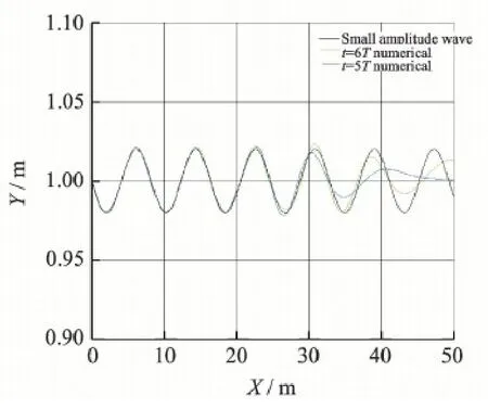
Fig.1 Numerical wave surface profiles of small amplitude wave
The physical time step is still selected as T/550 and the unsteady simulation is marched to t = 16 s.Fig.4 displays the numerical 3-D wave surface nearthe monopile support at t = 16 s.According to the right figure with a view angle vertical to the xoz plane,the wave surface is nearly overlapped along the y-direction.Fig.5 gives the numerical wave surface profiles in the xoz plane at three moments: t =13 s,t =14.3 s and t = 16 s.The numerical wave surface profile at t = 14.3 s,namely t = 5T,is in a good agreement with the given small amplitude wave model.The above analyses demonstrate that the size of this monopile support is too small to affect the wave flow.
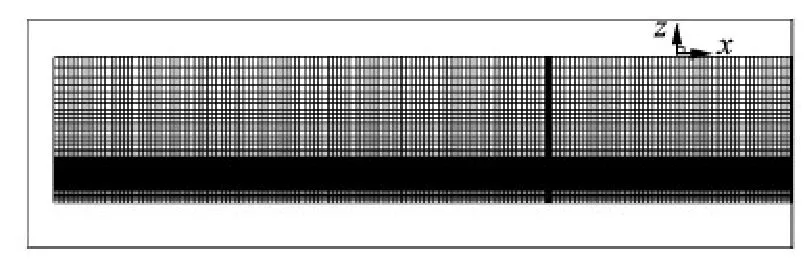
Fig.2 Y-directional surface grid of small-size monopile support
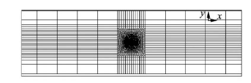
Fig.3 Z-directional surface grid of small-size monopile support
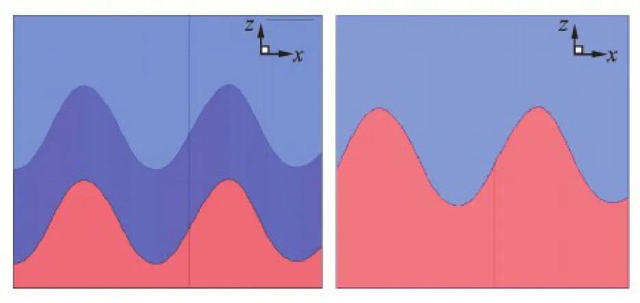
Fig.4 Numerical 3-D wave surface near small-size monopile support at t =16 s
Fig.6 compares the computed unsteady wave load on the small-size monopile support from t =13 s to t = 16 s with that from the Morison formula.It should be noted that the load refers to the horizontal force in this paper.A good agreement between these two methods validates the present load calculation method.
3.2Large-size monopile support under combined wind and wave
In this test case,the small amplitude wave flow past a large-size monopile support configuration is simulated.This monopile support is 70 m high and its constant diameter is 6 m.The wave parameters: the water depth h = 20 m,the wave height H = 0.8 m,and the wave period T =7 s.Then,the wave number k =0.087 3 and the wavelength equals 72 m.The ratio of support diameter to wavelength equals 0.083.The monopile support is located at a distance of 140 m from the inlet.The multi-block structured grid for this case has the same grid distributions as the smallsize monopile support.Based on the single wave condition,wind speeds of 10 m/s and 20 m/s are added to the air phase to conduct the load calculations for the monopile support under the combined action of wave and wind,respectively.

Fig.5 Numerical wave surface profiles near small-size monopile support in xoz plane
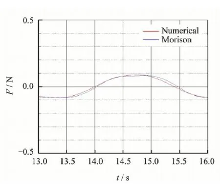
Fig.6 Unsteady wave load on small-size monopile support
The physical time step is T/550 and the computation is marched to t = 70 s,namely 10T.Fig.7 shows the numerical wave surface profiles in the xoz plane at t = 10T for three conditions: single wave,combined wave and 10 m/s wind,combined wave and 20 m/s wind.The numerical waves under the combined action of wave and wind almost overlap with that under single wave,since the effects of air flow on the water flow are negligible.Differing from the small-size case,the wave surface profile near this monopile support slightly deviates from the given small amplitude wave model,which indicates that the wave flow has been influenced by this large-size monopile support.
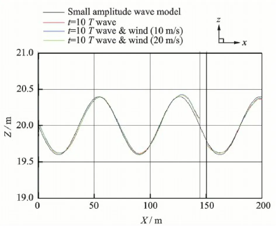
Fig.7 Numerical wave surface profiles near large-size monopile support in xoz plane
Fig.8 shows the computed unsteady load on the large-size monopile support from t = 40 s to t =70 s,in which the load equals the sum of aerodynamic and wave loads.The unsteady load curves for combined wave and wind can be approximately obtained from that for single wave through coordinate translation and the translation value increases with the increase of wind speed.
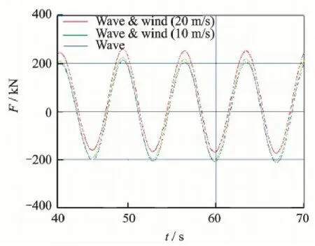
Fig.8 Unsteady load on large-size monopile support
For the combined wave and wind cases,define the load difference as the total load minus the wave load under action of single wave.Since the numerical waves of those three cases almost overlap with each other,this load difference approximately equals the aerodynamic load.It can be observed from the load difference curves in Fig.9 that the unsteady wave flow leads to the unsteady variation of aerodynamic load.
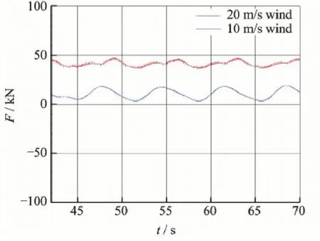
Fig.9 Load difference curves for large-size monopile support
4 Load Calculation of Monopile-Supported Offshore Wind Turbine
Finally,the unsteady load calculation is performed on a monopile-supported offshore wind turbine under combined action of small amplitude wave and wind with the 3-D N-S equations.This variable-diameter monopile support is 120 m high and Table 1 lists its geometric parameters in detail,where z =0 denotes the still water level and D the diameter of monopile support.The hub diameter is 6 m and the rotor diameter is 118 m.
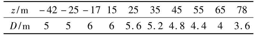
Table 1 Geometric parameters of variable-diameter monopile support
The wave parameters are: the water depth h =42 m,the wave height H =1.6 m,and the wave period T =2.86 s.Then the wave number equals 0.492 and the wavelength equals 12.77 m.The ratio of monopile support diameter to wavelength varies from 0.39 to 0.47.
In the present work,the pressure drop method is applied to consider the wind rotor effect on the flowfield.The pressure drop across the wind rotor is formulated as follows[13]

where ρ is the local air density,u the free air flow velocity,and CTthe rotor thrust coefficient.In this case,ρ= 1.225 kg/m3,u = 10 m/s,CT= 0.767 46,then Δp =47.006 9 Pa.
The monopile support is located at a distance of 48 m from the inlet.Fig.10 shows the surface and volume grid for this combination.
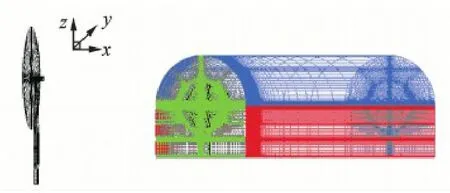
Fig.10 Surface and volume grid of monopile-supported offshore wind turbine
The physical time step is 0.01 s,which is less than T/550.The unsteady computation is marched in time until the mature numerical wave has propagated past the monopile support.Fig.11 displays the numerical wave surface profiles in the xoz plane at four moments within a wave period.It can be seen that the numerical wave near the inlet differs significantly from the given small amplitude wave model.A same phenomenon is found while the monopile support is removed,and further study indicates that it is caused by a larger ratio of wave amplitude to wavelength.Meanwhile,the numerical wave near the monopile support has been greatly affected by the monopile support due to a large ratio of monopile support diameter to wavelength.
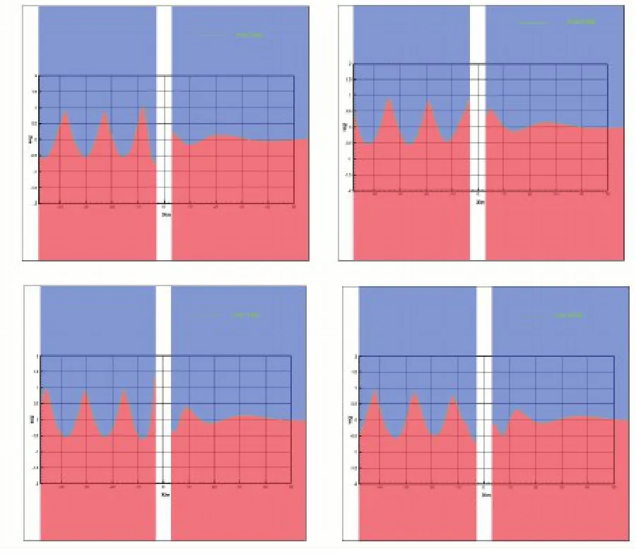
Fig.11 Numerical wave surface profiles near monopilesupported offshore wind turbine in xoz plane
Fig.12 shows the unsteady load on the monopiletower-hub combination.The load varies with time approximately in a periodical way after about 20 s.
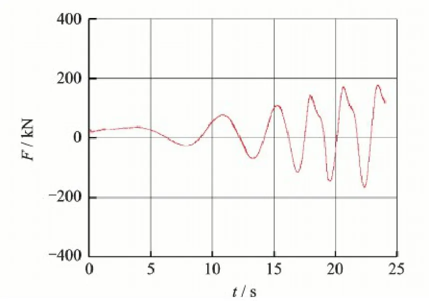
Fig.12 Unsteady load on monopile-tower-hub combination
5 Conclusions
Based on the Fluent software platform,an accurate unsteady load calculation method for the support configuration of a monopile-supported offshore wind turbine is established by simulating the air-water twophase flow with the N-S equations.With reasonable wave parameters,the numerical wave agrees well with the given small amplitude wave.The computed wave load on a small-size monopile support coincides with the Morison formula.In the future work,the present method will be developed to consider the real rotor blades and applied to predict the aeroelastic behaviours of an offshore wind turbine.
Acknowledgements
This work was supported partly by the National Basic Research Programof China (" 973 " Program )(No.2014CB046200),the National Natural Science Foundation of China (No.11372135),and the NUAA Fundamental Research Funds (No.NS2013005).
References:
[1]VELDKAMP H F,VANDER T J.Influence of wave modelling on the prediction of fatigue for offshore wind turbines[J].Wind Energy,2005,8(1) : 49-65.
[2]XU Jianyuan,ZHU He.Dynamic characteristic analysis of offshore wind turbine under combined wind and waveaction[J].Proceedings of the CSEE,2010,30(5) : 120-124.(in Chinese).
[3]LI Deyuan,LIU Shengxiang,ZHANG Xiangwei.Dynamical response numerical analysis of the offshore wind turbine tower under combined action of wind and wave [J].Journal of Mechanical Engineering,2009,45 (12) : 46-52.(in Chinese).
[4]HE Dexin.Wind engineering and industrial aerodynamics[M].Beijing: National Defense Industry Press,2006.(in Chinese).
[5]MORSON J R,JOHNSON J W,SCHAAF S A,et al.The force exerted by surface wave on piles[J].Journal of Petroleum Technology,1950,2(5) : 149-154.
[6]GUO Tongqing,LU Zhiliang,TANG Di,et al.A CFD/ CSD model for aeroelastic calculations of large-scale wind turbines[J].Science China Technological Sciences,2013,56(1) : 205-211.
[7]ZHONG Wei,WANG Tongguang.Numerical analysis of the wind turbine blade-tip vortex[J].Journal of Nanjing University of Aeronautics&Astronautics,2011,43 (5) : 640-644.(in Chinese).
[8]HUANG J,CARRICA P M,STERN F.Semi-coupled air/water immersed boundary approach for curvilinear dynamic overset grids with application to ship hydrodynamics[J].International Journal for Numerical Methods in Fluids,2008,58(6) : 591-624.
[9]DONG Zhi.Numerical modeling of nonlinear waves with VOF method and engineering applications[D].Guangzhou: Sun Yat-Sen University,2009.(in Chinese).
[10]LIU Xia,THAM L G,WANG Daguo.Numerical simulation of second-order Stokes based on wave-generation method of defining inlet boundary conditions[J].Journal of Liaoning Technical University: Natural Science E-dition,2010,29(1) : 107-111.(in Chinese).
[11]WANG Shuqing,LIANG Bingchen.Wave mechanics for ocean engineering[M].Qingdao: China Ocean University Press,2013.(in Chinese).
[12]GU Hanbing.Research and application of numerical model on waves action with obstacles[D].Tianjin: Tianjin University,2005.(in Chinese).
[13]ZHU Chong.Numerical simulation of wind turbine wake flow field[D].Nanjing: Nanjing University of Aeronautics and Astronautics,2012.(in Chinese).
Dr.GuoTongqing is an associate professor in the college of aerospace engineering at Nanjing University of Aeronautics and Astronautics (NUAA),where he received his Ph.D.Degree of Engineering in the department of aerodynamics in 2006.His research areas include computational fluid dynamics and aeroelastics.His major interest focuses on the CFD-based computational methods for unsteady aerodynamics and aeroelasticity and their applications in engineering.
Mr.Tong Xiaolong received his Master Degree of Engineering in the Department of Aerodynamics,NUAA in 2015.At present,he works as an assistant engineer in Shenyang Aircraft Design&Research Institute.His main research area is computational fluid dynamics.
Dr.Lu Zhiliang is a professor in the College of Aerospace Engineering at NUAA,where he received his Ph.D.Degree of Engineering in the department of aerodynamics in 1997.His research areas include aerodynamics andaeroelastics.His major interest is to develop efficient numerical methods for unsteady aerodynamics and aeroelasticity.His research achievements have been widely applied to the aircraft design.
(Executive Editor: Zhang Tong)
 Transactions of Nanjing University of Aeronautics and Astronautics2016年1期
- Transactions of Nanjing University of Aeronautics and Astronautics的其它文章
- Improvement of Mechanical,Dynamic-Mechanical and Thermal Properties for Noil Ramie Fiber Reinforced Polyethylene Composites
- Simulation of SLD Impingement on Wind Turbine Blade Airfoil
- Fatigue Assessment Method for Composite Wind Turbine Blade
- Gravity Effect on the First Natural Frequency of Offshore Wind Turbine Structures
- Coupled Aerodynamic and Hydrodynamic Analysis of Floating Offshore Wind Turbine Using CFD Method
- Numerical Analysis on Motion of Multi-column Tension-Leg-Type Floating Wind Turbine Basement