Optimization of three-loop missile autopilot gainunder crossover frequency constraint
M.A.ABD-ELATIF*,Long-jun QIAN,Yu-ming BO
School of Automation,University of Science and Technology,Nanjing 210094,China
Optimization of three-loop missile autopilot gainunder crossover frequency constraint
M.A.ABD-ELATIF*,Long-jun QIAN,Yu-ming BO
School of Automation,University of Science and Technology,Nanjing 210094,China
Received 25 June 2015;revised 18 August 2015;accepted 26 August 2015 Available online 21 September 2015
The open-loop crossover frequency is pointed as an important parameter for practical autopilot design.Since different gain designs may achieve the same open-loop crossover frequency,it should be neither considered as a performance objective of the optimal autopilot design-schemes nor neglected.Besides,the main assignment of the autopilot is to drive the missile to track the acceleration commands,so the autopilot gain design should be evaluated directly according to the resultant tracking performance.For this purpose,an optimal design methodology of the three-loop missile autopilot is introduced based on constraint optimization technique,where the tracking performance is established analytically as the design objective and the open-loop crossover frequency is formed as inequality constraint function,both are manipulated in terms of stable characteristic parameters of the autopilot closed-loop.The proposed technique is implemented with the assistance of a numerical optimization algorithm which automatically adjusts the design parameters.Finally,numerical simulation results are provided to demonstrate the effectiveness and feasibility of the proposed approach compared with that in some references.
Three-loop missile autopilot;Optimal gain design;Crossover frequency constraint;Performance optimization
1.Introduction
The main mission of missile autopilot is to track the guidance commands with a guaranteed level of system performance.In order to successfully achieve this mission,the performance characteristics of the autopilot must have a fast response to intercept a maneuvering target and reasonable robustness for system stability under the effect of un-modeled dynamics and noise.Basically,the concept of open-loop transfer function is the cornerstone of feedback control system analysis,where the relative stability and the robustness can be determined from analysis of the stability margins.However,Ref. [1]shows that ignoring the value of open-loop crossover frequency in the design procedure,even with good phase and gain margins,will cause design instability for relatively innocuous plant perturbations.In fact,this design may cause too high crossover frequency,which indicates that the system may go unstable when it is built and tested.Moreover,Ref. [2]concludes that the concept of open-loop gain and phase margins isnot as useful realistically at high frequency design due to the increase of model non-linearity,which leads to considerable difference between the predicted gain and phase values and their real values at high frequency.A common approach to address this problem is by modifying the crossover frequency value to make sure that the open-loop gain is below some desired level at high frequencies.This value is set based on the assumptions about the high-frequency modeling errors,sometimes based on test data,and often comes from hard-learned experience.A classical “rule of thumb”that addressed this value is introduced in Refs. [1,3].As a result,the crossover frequency is an important parameter in gain design process to achieve good trade-off between fastness and robustness.Nevertheless,in multi-loop autopilot design different gain combinations could meet the same open-loop crossover frequency with different f l ight performances.
Consequently,different methods and strategies have been implemented by researchers in order to introduce the open-loop frequency requirements into the autopilot design procedure. From optimal design prospective,some methods are considered as weight adjusted LQR technique for the objective of minimum error between desired and actual open loop crossover frequency [4-7].Although it is possible to get the samecrossover frequency for different gain designs,these techniques take the prescribed crossover frequency as the design goal;this scheme will not essentially guarantee an ideal autopilot. Besides,it is based on initial guessing of weights which might need to be carried out and repeated many times to adjust the required initial performance.In a different way,the multiobjective optimization technique is introduced in Ref. [8],where both time and frequency performance design aspects are combined into one objective function through multi-weight technique.Even so,this method optimizes the autopilot to a certain specif i ed performance level with the challenge of objective's weight adjustment.Moreover,Ref. [9]introduces a dynamic inversion technique,which uses a constraint optimization algorithm to get the design parameters for the autopilot system.However,this method is considered for a specif i ed controller structure with some assumptions and totally numerical procedure.In addition,the system stability is conf i rmed by the inequality constraints on gain and phase margins and minimum controller cycle,which may perform a hard optimization problem with some performance degradation.
Since the crossover dynamic itself cannot determine the total performance of the autopilot,so it is necessary to f i nd more reasonable objective function for optimal autopilot gain design so that an appropriate optimization technique can consider directly the open-loop crossover frequency constraint and avoid the burden of design weight adjustment.In this paper,an optimal autopilot gain design is introduced based on constraint optimization technique,where the tracking performance is set as design objective and the open-loop crossover frequency as design constraint.First,an analytical formula between the autopilot gain and the stable characteristic parameters of the autopilot closed loop is systematically derived.Then,the exact open-loop crossover frequency constraint is established in a form of analytical inequality.Moreover,the performance index ISE of the autopilot tracking error is analytically formed as the design objective [10-13].Both the objective and the constraint are manipulated in terms of the characteristic parameters. Finally,a constrained optimization problem is constructed and the optimal gain design is achieved for the corresponding optimum design parameters with the assistance of an optimization algorithm.This work is extended to numerical autopilot design of a typical missile system using the proposed technique,and the results are compared with the design strategy of Ref.[14].
2.Missile modeling and analytical gain formula
The classic three-loop missile autopilot [15,16],namely Raytheon autopilot,depicted in Fig.1,is the topology considered throughout this paper.Mathematically,the airframe transfer function input is the f i n def l ection,and the output is the achieved missile acceleration.The missile airframe dynamics is determined by six-dimensional equations of forces and moments acting on the missile body.The longitudinal missile dynamics,using the small disturbance linearization assumptions,are given as

where ϑ is the body pitch angle,θ is the trajectory angle,α is the angle of attack,V is the missile velocity,δ is the fi n de fl ection,ayis the missile acceleration,and Mα,Mδ, Mq,Zαand Zδare the aerodynamics coef fi cients [3].The missile airframe transfer functions can be written as
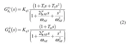
where
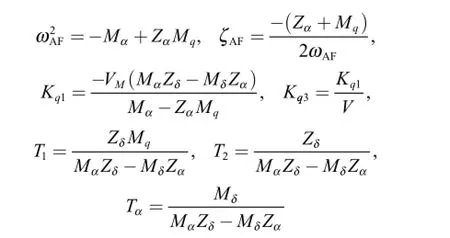

Fig.1.Raytheon three-loop autopilot.
The Raytheon autopilot is composed of rate loop,syntheticstability loop and accelerometer feedback loop with feedbackgains Kg,Kωand KAfor each loop respectively.These gains must be designed carefully to satisfy the desired performance. The gain KDCis computed from the above three gains so that the achieved acceleration will match the commanded acceleration.Regarding Fig.1,the closed-loop transfer function of the three-loop autopilot is computed from the inner to the outer loop through the following steps.
Rate loop transfer function is written as

The transfer function of stable-synthetic loop with rate loop is given as

Then,the transfer function of the open forward loop is written as

where

Finally,the close-loop transfer function is given as

For a stable closed-loop,the characteristic polynomial of the three-loop autopilot can be described by three positive parameters τ,ζ and ω with a real and a pair of conjugate complex stable poles [3],where the desired close-loop transfer function of the autopilot is written in the following form:

The positive selection of the three parameters guarantees the stability of the autopilot closed-loop.Moreover,the autopilot performance is totally described by these design parameters.In the following,an analytical formula between the autopilot gain and the design parameters is derived by equating both transfer functions (4)and (5)to obtain

and

where the inverse matrix is well def i ned for applicable missile parameters with the assumption that T1≪ Tαand T2≪ Tα. Furthermore,regarding Eq.(3),the autopilot gains KA,Kωand Kgcan be calculated with analytical functions

in terms of design parameters τ,ζ and ω.Furthermore,KDCis computed from the above three gains as

Based on Eqs.(5)and (7),the autopilot design is handled by the parameters τ,ζ and ω to achieve the desired performance requirements.For optimal gain design,these parameters are tuned to the optimum of certain cost function.The tuning technique should be carried out under the system limitations,so the crossover frequency constraint will be highlighted in the next section.
3.Crossover frequency constraint function
For robust and adequate control properties,frequency domain speci fi cations are speci fi ed using the crossover frequency and stability margins of the open-loop system.The crossover frequency must be chosen to be high enough to ensure a wide autopilot bandwidth but low enough to prevent stability problems due to actuator,rate gyro and other un-modeled dynamics.The limit of crossover frequency can be determined by system stability requirements and fi n actuator performance.According to the classical “rule of thumb”,the crossover frequency should be less than one-third of the actuator bandwidth ωACT[1,3].The open-loop transfer function of the three-loop autopilot with loop broken right before the fi n actuator is expressed as

The open loop magnitude ratio is written as

For practical autopilot,the crossover frequency is beyond the airframe fundamental dynamic frequency,i.e.ωAF<ωACT. Moreover,the magnitude trajectory of the open-loop transfer functionGop(s) will cross the 0 dB line only once.At the crossover frequency,the magnitude ratio isequal to one,i.e.Therefore crossover frequency constraint should satisfy the following inequality:

where ωCRdis the prescribed limitation of ωCR,that is,for any gain combination K1,K2and K3satisfying Eq.(10),then the corresponding ωCRwill beωCR≤ ωCRd<13ωACT.Referring to Eqs.(6)and (10),the crossover frequency constraint function is equivalently expressed in terms of τ,ζ,ω and ωCRdas

where

4.Optimal autopilot gain design
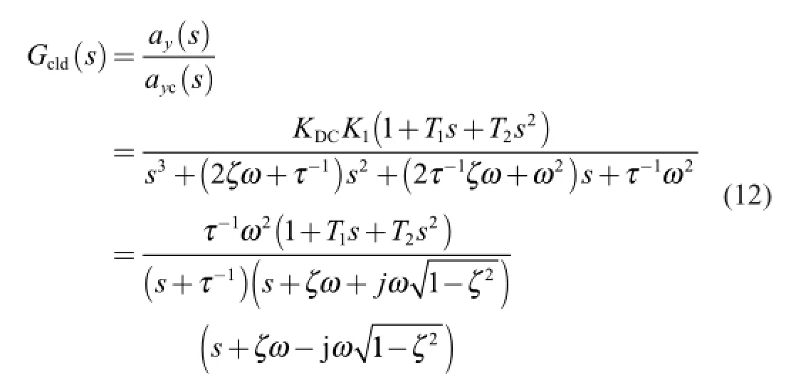
The main objective of the autopilot system is to force the missile to follow the steering commands developed by the guidance system.According to Eqs.(5),(6)and (9),the positive parameters τ,ζ and ω are tuned to minimize the integral error criteria of the input-output of the autopilot closed-loop transfer function:
Integral of various functions of error between the reference input and the controlled plant output is a powerful quantitative measurementofthesystemperformance.Thereareseveralkinds of integral error criteria to describe the system performance [8]. Among them,the integral of the square of the error (ISE)

is chosen as the command tracking performance index of the autopilot with the consideration of obtaining its analytical expression.Referring to Eq.(12),with partial fraction expansion,the unit step response is expressed as

where
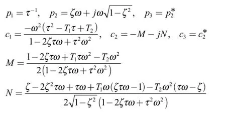
By inverse Laplace transform,the unit step output response in the time-domain is given as

and the error for unity command tracking is expressed as

Therefore,the analytical objective function of ISE performance index can be written as
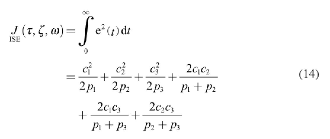
The value of the above ISE analytical formula is always a real positive number due to complex conjugated relation in Eq.(14).Then optimal autopilot gain design is stated in the form of constrained optimization problem as
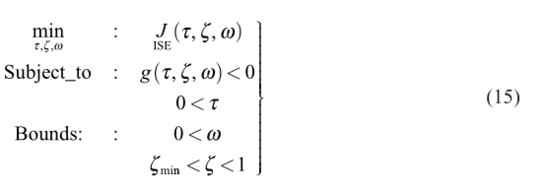
This optimization problem is the core of the introduced optimal technique,where the objective functionIJ
SE(τ, ζ, ω)isthe performance evaluation scale and the constraint g(τ,ζ,ω)is the performance limitation for practical design.The bounds of design parameters are set to positive values to ensure the system stability for the whole space of the cost function.Since the crossover frequency cannot satisfy the total performance requirements,it is needed to set a lower limit for the closed loop damping parameter ζmin> 0,usually it is about 0.7.Referring to Table 3,this limit shall guarantee a suf fi cient system damping and phase margin.Particularly,the optimization problem (Eq.15)is a nonlinear constrained multi-variable optimization problem.As expected,the function fmincon of the MATLAB OptimizationToolbox can solve such kind of smooth objective optimization problem well effectively with feasible initial design parameters.Moreover,it converges to the same minimum point even starting from different initial guesses.In this line of thought,the optimal autopilot gains KA,Kωand Kgare easily calculated by substituting the optimum parameters τ,ζ and ω into Eqs.(7)and (8)without the need for design weight adjustment.

Table 1Typical missile aerodynamic data.
5.Numerical analysis
In this section,numerical analysis is carried out to show the effectiveness of the proposed optimal technique for autopilot gain design.Data of a typical missile system [14],listed in Table 1,are used for this purpose.Moreover,the actuator is considered as a second-order dynamic system with naturalfrequency ωACT=220rad/s and damping factor ζACT=0. 65.Let ωCRd=50rad/s be used as the upper limitation to the open-loop crossoverfrequency, which guarantees the open-loop system to have about 30°of the phase margin after considering the phase lags caused by autopilot's hardware systems [14].
In the following,the numerical analysis is introduced through two steps.In the fi rst step,the proposed technique is applied to introduce some analysis for the considered optimization problem,and the nature of its cost function alsoemphasizes the achievement of required crossover frequency for practical optimal design of autopilot system.Moreover,the lower boundζmin of damping factor is examined for proper setting.In the second step,the introduced technique is compared to another design strategy with the same crossover frequency requirement.
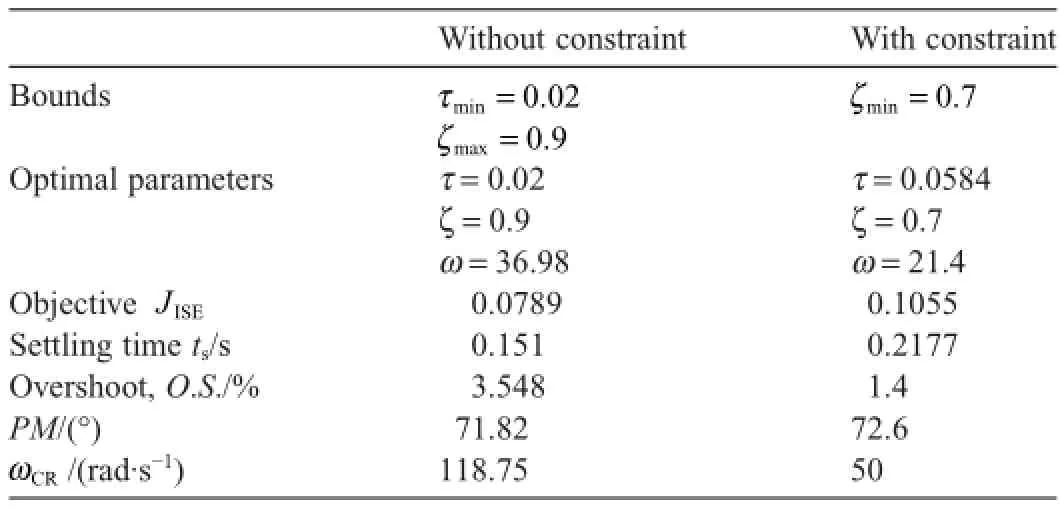
Table 2Optimal design performance with and without constraint.
First,the objective function (Eq.14)of the optimization problem (Eq.15)is the performance evaluation scale and it could be described as three-dimensional search space def i ned by the design parameters τ,ζ and ω.This space is formed by multi-surfaces for different values of ζ.Specif i cally,each particular point in this space corresponds to particular autopilot gain combination with particular response based on the analytical equation (7).Fig.2(a)exhibits the smooth objective space for the specif i ed region of the three design parameters without applying the crossover frequency constraint.The objective space after applying the crossover frequency constraint can be observed in Fig.2(b),where the unf i tted portion is removed.In both cases the optimization technique easily converges to the minimum point.The optimal design of both cases,with and without the crossover frequency constraint,is introduced in Table 2.Clearly,the constraint design achieves the open-loop crossover frequency within the constraint limit,while the unconstrained autopilot design derives very high open-loop crossover frequency which is compatible with the conclusion in Ref. [1].Furthermore,as listed in Table 3,for the constraint case,the smallest value of objective ISE mostly belongs to the surface of smaller value of ζ.As a result,the optimum performances express degradation in phase margin and overshootvalue even with good tracking performance.In order to achieve suf fi cient system damping and phase margin,a prescribed ζmin> 0is set as the lower bound of damping factor ζ.The results show that the bound ζmin=0. 7achieves a good compromise between system response and robustness with suf ficient phase margin,appropriate overshoot and settling time.
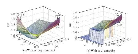
Fig.2.ISE objective search space of certain design parameters period.(a)Objective function space without ωCRconstraint.(b)Objective function space after ωCRconstraint.

Table 3Constraint optimal design performance for different ζminbound.

Fig.3.Performance comparison with different strategies.(a)Acceleration response for 5g input command.(b)The f i n def l ection response for 5g input command.
Second,the proposed technique is compared to the design strategy of Ref. [14]for the three-loop autopilot design.This strategy is keen on adjustment of the design parameters for single objective of minimizingSpeci fi cally,this strategy is pole adjustment technique where the pole position is described by τ,ζ and ω.Both τ and ζ are prescribed,while ω is tuned to minimize the crossover frequency objective with unclear relation between ω andωCR.Likewise,the strategies in Refs. [4-7]are LQR approach with weight adjustment procedure for minimizing the same objective.On the other hand,the proposed approach freely optimizes the whole three parameters for minimum tracking objective that satis fi es the crossover frequency constraint.
To illustrate,the tracking performances of acceleration command 5g are displayed in Fig.3(a),and the numerical comparison results are stated in Table 4.The simulation results show that the proposed optimal design method derives much better tracking performance than that in Ref. [14],even if the open-loop crossover frequencies and phase margins in both cases are almost the same.Moreover,the related f i n def l ections are demonstrated in Fig.3(b),where the exhibited elevator def l ections reach the same steady value since it is totally determined by the aerodynamic parameters and the f l ight velocity ofthe missile.Besides,the slight larger elevator def l ection and def l ection rate introduced by the proposed technique during transient time serves as a payment for the faster response.Since the role of the autopilot system is to drive the missile to track the acceleration commands,so its tracking performance should be the main point to evaluate the design quality within the applicability dynamic constraints.
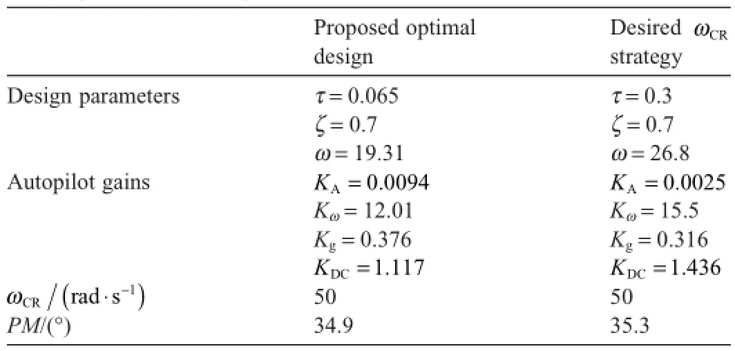
Table 4Design performance comparison.
6.Conclusion
Optimal design technique is proposed for the three-loop missile autopilot.The command tracking performance is established as the design objective using the analytical form of the integral square of the autopilot closed-loop tracking error. Moreover,the design practicality and robustness are achieved by an inequality constraint on the system open-loop crossoverfrequency.Then a constrained optimization problem is constructed in terms of stable characteristic parameters of the autopilot closed-loop.The optimum design parameters are automatically achieved with the assistance of a numerical optimization algorithm.Numerical simulations show that the proposed method can provide a better tracking performance with the required robustness level.
[1]Nesline FW,Zarchan P.Why modern controllers can go unstable in practice.J Guid Control Dyn 1984;7(4):495-500.
[2]Jackson PB.Overview of missile f l ight control systems.Johns Hopkins APL Tech Dig 2010;29(1):9-24.
[3]Zarchan P.Tactical and strategic missile guidance.Reston,VA:American Institute of Aeronautics and Astronautics;2002.p.483-526.
[4]De-fu L,Jun-fang F,Zaikang Q,Yu M.Analysis and improvement of missile three-loop autopilots.J Syst Eng Electron 2009;20(4):844-51.
[5]Hui W,Defu L,Jiaxin W,Tao S.An analytical design method for the missile two-loop acceleration autopilot.In:Tianyuan X,Lin Z,Shiwei,M,editors.System simulation and scientif i c computing (ICSC).Heidelberg: Springer;2012.p.157-65.
[6]Fan J,Su Z,Li Q,Dong S.Design and control limitation analysis of two-loop autopilot.In:2011 Chinese control and decision conference(CCDC).Mianyang,China:IEEE;2011.p.3814-18.
[7]Lidan X,Kenan Z,Wanchun C,Xingliang Y.Optimal control and output feedback considerations for missile with blended aero-f i n and lateral impulsive thrust.Chin J Aeronaut 2010;23(4):401-8.
[8]Sreenuch T,Tsourdos A,Hughes E,White B.Lateral acceleration control design of a non-linear homing missile using multi-objective evolution strategies.In:American Automatic Control Council,editor.Proceedings of the 2004 American control conference,vol.4.Boston,MA: ETATS-UNIS;2004.p.3628-33.
[9]Byoung-Mun M,Daekyu S,Min-Jea A,Byoung-Soo TK.Missile autopilot design via output redef i nition and gain optimization technique. In:SICE 2007 annual conference.Takamatsu,Japan:IEEE;2007.p. 2615-19.
[10]Duarte-Mermoud MA,Prieto RA.Performance index for quality response of dynamical systems.ISA Trans 2004;43(1):133-51.
[11]Kumar C,Jebakumar JS,Mishra B.Controller selection and sensitivity check on thebasisofperformanceindex calculation.IJEEDC 2014;2(1):91-3.
[12]Patra J,Sarathi P,Samal S.Analysis and comparison of different performance index factor for conventional PID and GA plus PID controller.IJETCAS 2013;4(3):242-50.
[13]Hussain KM,Rajendran RA,Kumar MS.Comparison of tuning methods of PID controllers for FOPTD system.IJIREEICE 2014;2(3): 1177-80.
[14]Qiu-Qiu W,Qun-Li X,Zai-kang Q.Pole placement design with open-loop crossover frequency constraint for three-loop autopilot.Syst Eng Elect 2009;2:420-3 [in Chinese].
[15]Mracek CP,Ridgely DB.Missile longitudinal autopilots:comparison of multiple three loop topologies.In:AIAA guidance,navigation,and control conference and exhibit,San Francisco;2005.p.917-28.
[16]Jun-Fang F,Bao-Cai S,Zhong S,Si-Yu D.A novel analysis for tactical missile autopilot topologies.In:31st Chinese control conference (CCC). Hefei,China:IEEE;2012.p.2316-20.
Peer review under responsibility of China Ordnance Society.
*Corresponding author.Tel.:08615905193644.
E-mail address:Mdyosf2010@yahoo.com (M.A.ABD-ELATIF).
http://dx.doi.org/10.1016/j.dt.2015.08.006
2214-9147/© 2015 China Ordnance Society.Production and hosting by Elsevier B.V.All rights reserved.
© 2015 China Ordnance Society.Production and hosting by Elsevier B.V.All rights reserved.
- Defence Technology的其它文章
- Azo-bridged triazoles:Green energetic materials
- Friction assisted solid state lap seam welding and additive manufacturing method
- Ballistic behavior of boron carbide reinforced AA7075 aluminium alloy using friction stir processing-An experimental study and analytical approach
- Enhancement of seal life through carbon composite back-up rings under shock loading conditions in defence applications
- Studies on impact sensitivity of nanosized trinitrotoluene (TNT)conf i ned in silica processed by sol-gel method
- Effect of f i bre orientations on the mechanical properties of kenaf-aramid hybrid composites for spall-liner application

