Hierarchal Decomposition for the Structure-Fluid-Electrostatic Interaction in a Microelectromechanical System
Daisuke Ishihara,Tomoyoshi Horie,Tomoya Nihoand Akiyoshi Baba
Hierarchal Decomposition for the Structure-Fluid-Electrostatic Interaction in a Microelectromechanical System
Daisuke Ishihara1,2,Tomoyoshi Horie1,Tomoya Niho1and Akiyoshi Baba3
In this study,a hierarchal decomposition is proposed to solve the structure-fluid-electrostatic interaction in a microelectromechanical system(MEMS).In the proposed decomposition,the structure-fluid-electrostatic interaction is partitioned into the structure-fluid interaction and the electrostatic field using the iteratively staggered method, and the structure-fluid interaction is split into the structure fluid velocity field and the fluid pressure field using the projection method.The proposed decomposition is applied to a micro cantilever beam actuated by the electrostatic force in air.It follows from the comparisons among the numerical and experimental results that the proposed method can predict the MEMS vibration characteristics accurately.
structure-fluid-electrostatic interaction,decomposition,partitioning,splitting, finite element method, microelectromechanical system, staggered method,projection method
1 Introduction
Microelectromechanical system(MEMS)is typically smaller than 1 millimeter and larger than 1 micrometer in size[Gad-el-Hak(1999)].At these size scales,surface force is superior to body force due to the scale effect.Therefore,MEMS is often driven by the electrostatic force,and its vibration under atmospheric condition[Mihara,Ikehara,Konno,Murakami, Maeda,Fukawa,and Kimura(2011)]is strongly damped by the fluid viscous force from the surrounding[Cho,Pisano,and Howe(1994)].Moreover,both of these forces are sensitive to the dynamical behavior of
MEMS.Therefore,the interaction of the structure,fluid and electrostatic field or the structure–fluid–electrostatic interaction has to be carefully taken into account during the design process in order to predict the vibration characteristics such as the resonance frequency and the damping ratio,which are the key design parameters[De and Aluru(2006)].
Initially a partitioned algorithm was proposed for the structure-electrostatic interaction[Shi,Ramesh,and Mukherjee(1996)].Then a monolithic algorithm was proposed in order to analyze a pull-in[Rochus, Rixen,and Golinval(2005,2006);Ghosh and Mukherjee(2009);De and Aluru(2004)].Recently a monolithic algorithm for the structure-fluid-electrostatic interaction was proposed[De and Aluru(2006);Rochus,Gutschmidt,Cardona,and Geuzaine(2012);Ghosh and Mukherjee(2009)].However,the monolithic analysis tends to be expensive computationally[Rugonyi and Bathe(2001)].Generally,complex coupled systems can be analyzed using decomposition[Felippa,Park,and Farhat(2001)].Therefore,instead of the monolithic analysis,the decomposed analysis for the structure-fluid electrostatic interaction is expected for the purpose of computational efficiency.
In this study,a hierarchal decomposition is proposed in order to solve the structure fluid - electrostatic interaction.In the proposed decomposition,the entire system is partitioned into the mechanical and electric subsystems or the structure-fluid interaction and the electrostatic field using the iteratively staggered method,and the structure-fluid interaction is split into the structure-fluid velocity field and the pressure field using a projection method[Ishihara and Horie(2014)].Moreover,the structure-fluid velocity field is partitioned into the structural velocity field and the fluid velocity field using an explicit method.In this way,the proposed decomposition consists of the partitioning and the splitting in a hierarchical way.Therefore,it is called the hierarchal decomposition.The proposed decomposition is implemented using the finite element method and is applied to a micro cantilever actuated by the electrostatic force in vacuum and air.It follows from the comparisons among the numerical and experimental results that the proposed method taking into account the full interaction can predict the vibration characteristics of MEMS accurately.
2 Equation system for structure-fluid-electrostatic interaction
2.1 Governing equations
The open air surrounding MEMS can be regarded as an incompressible fluid[Ye,Wang,Hemmert,Freeman,and White(2003);Beskok,Karniadakis,and Trimmer(1996)],and the nonlinear inertial force can be negligible compared to the viscous force due to the scale effect[Cho,Pisano,and Howe(1994)].Moreover,the finite-size effect on the drag force is significant[Ye,Wang,Hemmert,Freeman,and White(2003)]. Therefore,instead of simplified fluid models such as the Reynold’s squeeze film model[Rochus,Gutschmidt,Cardona,and Geuzaine(2012);Lee,Tung, Raman,Sumali,and Sullivan(2009);Chang,Lee,and Li(2002);De and Aluru(2006);Xu and Sun(2011)],the incompressible Stokes’model[Ye,Wang,Hemmert,Freeman,and White(2003);Deand Aluru(2006);Ghosh and Mukherjee(2009);Mukherjee,Telukunta,and Mukherjee(2005)]is used in this study.Let us de fineas the domains of structure,fluid,and electrostatic field for each instant of timet,respectively,andas the structure-fluid and structure-electrostatic interfaces,respectively,where the superscripts s,f,e,sf,and se denote the quantities of structure,fluid,electrostatic field,structure-fluid interaction,and structure-electrostatic interaction,respectively.
The incompressible Stokes’equation can be expressed as

where ρ is the mass density,viis theith component of the velocity vector(i=1,2,and 3),σijis theijth component of the Cauchy stress tensor(j=1,2,and 3),andgiis theith component of the body force vector.The air is assumed to be Newtonian.Since rarefaction effects are unlikely to be significant at the size scales of MEMS,no-slip boundary conditions are used[Gad-el-Hak(1999);Beskok,Karniadakis,and Trimmer(1996)].The arbitrary Lagrangian-Eulerian(ALE)method[Hughes,Liu,and Zimmerman(1981)]is used to describe the moving boundary.
The equilibrium equation for the elastic body can be expressed as

whereuiis theith component of the displacement vector.The strain is such small that the linear elastic material is assumed,while the geometrical nonlinearity is taken into account since MEMS often undergoes finite deformation[Li and Aluru(2001);Hu,Yang,and Kitipornchai(2010);De and Aluru(2006);Rochus,Rixen,and Golinval,(2007)].
The electrostatic potential ϕesatis fies the following Laplace equation:

Theith component of the electrostatic field vectoris given by the following equation:

Theith component of the electrostatic force vectoracting on the conductor’s or structural surface is given by the following equation:

whereis theith component of the outward unit normal vector on the conductor’s or structural surface,and ε is the dielectric constant.
The following geometrical compatibility and equilibrium conditions(the structure fluid interface condition)are imposed on the structure-fluid interface:


2.2 Space discretization
Applying finite element discretization to Eqs.(1a,b),the equilibrium equation system and the incompressibility constraint can be obtained in matrix form,respectively,as

where M is the mass matrix,C is the diffusive matrix,G is the divergence operator matrix,g is the external force vector,a is the acceleration vector,v is the velocity vector,p is the pressure vector,Q is the internal force vector including all effects,the subscript L indicates the lumping of the matrix,and the subscript T indicates the transpose of the matrix.
Applying finite element discretization to Eq.(2),the equilibrium equation system can be obtained in matrix form as

where qsis the elastic internal force vector,which is the nonlinear function of the structural displacement vector us.Since MEMS can undergo large deformation[Li and Aluru(2001);Hu,Yang,and Kitipornchai(2010);De and Aluru(2006);Rochus,Rixen, and Golinval,(2007)],the finite deformation is taken into account using the total Lagrangian formulation,where the Hooke’s law is used for the relation between the second Piola-Kirchhoff stress and the Green-Lagrange strain under the assumption of small strain.
The structure-fluid interface conditions(6a)and(6b)can be rewritten in vector form,respectively,as

and

where the subscript c indicates the coupled degrees of freedoms(DOFs).
Eqs.(8),(9),and(10)can be rewritten as the following monolithic equation system:

and

where the matrices and the vectors appearing in these equations are defined as


where the subscriptiindicates uncoupled DOFs.
Taking into account Eq.(7),the equilibrium equation for the interaction of the fluid,structure,and electrostatic field can be given as

where the right–hand side geis the electrostatic force vector acting on the structure,which is the function of us,and can be given as follows:
First,the electric potential vector ϕeis derived using the following finite element equation for Eq.(3):

where Leis the Laplacian matrix.
Next,the electrostatic filed Eeis derived using the following finite element equation for Eq.(4):

where Meand Geare de fined,respectively,as

whereVeis the volume of elementeandNiis the shape function.
Finally,substituting Eeinto Eq.(5),the nodal values of the electrostatic force are derived,and their integrals on the structural surface give the equivalent nodal electrostatic force vector gein Eq.(13).
3 Hierarchal decomposition
3.1 Multilevel decomposition hierarchy
For two- field coupled systems,various decomposition algorithms have been proposed by many researchers.In Ref.Minami and Yoshimura(2010),some strongly coupled partitioned algorithms were compared with each other using typical test problems in a systematic way.For multi- field coupled systems,also,the decomposition is possible,and,usually,it has a multilevel hierarchy(multilevel decomposition hierarchy)[Felippa,Park,and Farhat(2001)].For example,the structure of an airplane can be decomposed into substructures such as wings according to their function,and substructures can be further decomposed into subdomains to accommodate parallel computing requirements[Felippa,Park,and Farhat(2001)].The basic idea proposed here is that the multilevel decomposition hierarchy that characterizes each level system as two- field coupled system can give the multi field decomposition algorithm reusing existing two- field decomposition algorithms in a systematic way.In this study,a new hierarchal decomposition based on this idea is proposed in order to solve the structure-fluid-electrostatic interaction.As shown in Fig.1,the proposed method has the following multilevel decomposition hierarchy:
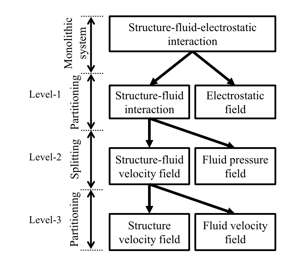
Figure 1:Hierarchal decomposition for the structure-fluid-electrostatic interaction.
In the first level,the structure-fluid-electrostatic interaction is partitioned into the structure-fluid interaction and the electrostatic field using the iteratively staggered method.In the second level,the structure-fluid interaction is split into the structure fluid velocity field and the fluid pressure field using the projection method.In the third level,the structure-fluid velocity field is partitioned into the structural velocity field and the fluid velocity field using the explicit method.
3.2 Partitioning using the iterative staggered method
Regarding the structure-fluid interaction as a single mechanical subsystem,the structure-fluid-electrostatic interaction is characterized as a two- field coupled system or a mechanical-electric coupled system.This physical consideration can drive the decomposition at the first level in Fig.1 as follows:
The iteratively staggered method has been successfully used for partitioning the structure-electrostatic interaction[Shi,Ramesh,and Mukherjee(1996)],which is a most fundamental mechanical-electric coupled system.Similarly,it can be used to partition the structure-fluid-electrostatic interaction into the mechanical and electric subsystems or the structure-fluid interaction and the electrostatic field.Let us consider the nonlinear iteration for the equilibrium equation(13)at the current time

Following this equation,the structure-fluid interaction and the electrostatic field are solved separately as follows:
The nodal vector of the electrostatic field Eeis derived from Eq.(15)for the known structural displacementt+Δtus(k-1).Then,the equivalent nodal force geacting on the structural surface is derived from Eeusing Eq.(5)and the surface integral.Substituting the derived geinto the right-hand side of Eq.(17)and using the expression of Eqs.(11a,b),the equations for the structure-fluid interaction can be written as follows:

Since Eq.(18a)is nonlinear equation,it is linearized using the increments of the acceleration,velocity,displacement,and pressure Δa,Δv,Δu,and Δp as

where Δa,Δv,Δu,and Δp are de fined,respectively,as


where the linear relations among Δa,Δv, and Δu based on the New mark’s β method are used,and M∗appears in the left-hand side of Eq.(19)is the generalized mass matrix,which is defined as

where K is defined using the tangential stiffness matrix Ksor the Jacobian matrix of qsas

and Δg appears in the light-hand side of Eq.(19)is the residual force,which is defined as

3.3 Splitting using the projection method
The projection method for the incompressible fluid has been gaining popularity in the computational fluid dynamics[Guermond,Minev,and Shen(2006)],and,most recently,it has been applied for the structure-fluid interaction including the fluid incompressibility[Ishihara and Yoshimura(2005);Fernandez,Gerbeau,and Grandmont(2007);Idelsohn,Del Pin,Rossi,and Onate(2009);Ishihara,Kanei,Yoshimura,and Horie(2008);Ishihara and Horie(2014);Badia,Quaini,and Quarteroni(2008a,b)].Their applications can be seen,for example,in Refs.Ishihara,Horie,and Denda(2009);Ishihara,Horie,and Niho(2014).In these studies,the monolithic equation system for the structure-fluid interaction is split into its subsystems algebraically.When the block-LU factorization[Badia,Quaini,and Quarteroni(2008a,b)]or the sub-structuring[Ishihara and Yoshimura(2005);Idelsohn,Del Pin,Rossi,and Onate(2009);Ishihara,Kanei,Yoshimura,and Horie(2008)]is used for the splitting,the Schur complement is inevitably produced during the formulation.Therefore,a major concern in these studies is how to approximate the Schur complement without loss of robustness[Minami and Yoshimura(2010);Fernandez and Moubachir(2005);Idelsohn,Del Pin,Rossi,and Onate(2009);Zhang and Hisada(2004);Heil(2004)].On the contrary,the algebraic splitting proposed in Ref.Ishihara and Horie(2014)uses the intermediate state variables and never produces any Schur complement during the formulation.Therefore,in this study,it is used to split the structure-fluid interaction into the structure-fluid velocity field and the pressure field as shown in Fig.1.The formulation is summarized as follows:
Let us assume the intermediate state variables satisfy the equilibrium equation(18a)for the known pressuret+Δtp(k-1).Then,Eq.(18a)is linearized as

where Δâ is the increment of the intermediate acceleration.Subtracting both sides of Eq.(24)from those of Eq.(19)and similarly subtracting Eq.(20b)from the following equation:

and substituting the result into the first difference gives,after suitable rearrangement,

Left multiplying both sides of Eq.(26)byτGLM-1,the following equation is obtained:

where Eq.(21)is used.It is shown from Eq.(27)that the incompressibility constraint(18b)for the unknown fluid velocityt+Δtv(k)is satisfied solving the following pressure Poisson equation(PPE):

When the PPE(28)is solved,Eq.(27)is reduced as

Since the present nonlinear iterations will be convergent,t+Δtˆv(k)agrees witht+Δtv(k)asymptotically as

Therefore,the second term of Eq.(29)will vanish,and the incompressibility constraint(18b)for the current fluid velocity is satisfied.
The predictor-multicorrector algorithm (PMA) for the FSI [Zhang and Hisada(2001)]is used for the time integration.The loop of the iterative procedure corresponds to the multicorrection loop of PMA and the relation(20)corresponds to the corrector of the PMA.The predictor of the PMA is given by Newmark’s β method as

whereta,tv,tu,andtp are the known acceleration,velocity,displacement,and pressure that are obtained in the previous time stept.
The solution procedure using the proposed hierarchal decomposition is summarized in Fig.2.As shown in this figure,in each iterationk,the FSI is solved after the electrostatic force is derived as follows:
Step 1:The increment of the intermediate acceleration Δâ is derived from the linearized equilibrium equation for the previous pressuret+Δtp(k-1)(24),and the intermediate velocityt+Δtˆv(k)is obtained from Eq.(25).
Step 2:The pressure increment Δp is derived from the PPE(28).
Step 3:The acceleration increment Δa is derived from the linearized equilibrium equation for the current pressuret+Δtp(k)(19),and then the accelerationt+Δta(k),the velocityt+Δtv(k),and the displacementt+Δtu(k)are obtained from the relation(20).
3.4 Partitioning using the explicit method
The structure-fluid velocity field can be further partitioned into the structure velocity field and the fluid velocity field using the explicit method.Let us use the following generalized mass matrix instead of(21):

where the diffusive term in Eq.(18a)is evaluated using the known velocity field.In this case,the fluid interior DOFs of M∗is reduced to the diagonal matrix.Therefore,the linearized equilibrium equations(19)and(24)can be partitioned into itsfluid interior part and the structural part without any algebraic operation.The equilibrium equation(19)can be partitioned into

Figure 2:Solution procedure of the proposed analysis.

and

while the equilibrium equation(24)can be partitioned into

and

Eqs.(33a)and(34a)have the structural DOFs,while Eqs.(33b)and(34b)have the fluid interior DOFs.Note that this partitioning requires the following necessary condition(Diffusion number condition)imposed on the time increment Δtfor the stability of the time integration:

where µfis the fluid viscosity,and Δhfis the minimum size of fluid elements.
4 Coupled analysis of MEMS
4.1 Problem setup
The present problem is schematically shown in Fig.3.A micro cantilever beam is driven by the electrostatic force and vibrates in vacuum(under 2Pa)and air.The beam is actually made using a chemical etching for a SOI wafer chip as shown in Fig.4.The top and base layers of the chip are made of arsenic-doped single crystal Si,which is conductive,and the middle layer of the chip is made of SiO2,which is isolated.The beam has the dimensions of the lengthL=1.00×103µm and the widthW=36µm,which are identified from the metallurgical microscope images,while the thicknessH=3.0µm and the gap lengthG=5.0µm,which are identified from the scanning electron microscope(SEM)images.The voltageVsas shown in Fig.5 is supplied between the top and base layers using the high-speed DC supply via Au electrodes.The risetime ofVsis approximately 50µsec.The convergence value ofVsis denoted by¯Vs.In the present chip, the top and base layers are electrically bridged andVsis divided between the equivalent resistances of the top layer and the gap.Therefore,the gap voltage between the beam and the baseVgis reduced fromVsconstantly,and the reduction rate is estimated at approximately 82%.The velocity of the deflection at the free end of the beamvtipis measured using the laser doppler vibrometer(the laser spot diameter 3µm,the resolution 0.05µm/sec,Ono Sokki Co.,Ltd.,Japan).Vsandvtipare simultaneously collected using a data acquisition system with a sampling speed of 500,000Hz,which is far larger than the natural frequency of the beam.

Figure 3:Schematic view of the problem setup.The micro cantilever beam is driven and vibrated by the electrostatic force generated by the step voltage applied between the top layer including the beam and the base layer.
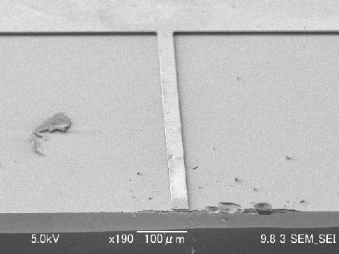
Figure 4:Example of the SEM images of the micro cantilever beam.
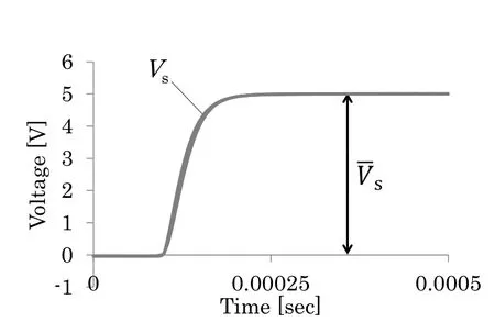
Figure 5:Example of time history of the supplied voltage.
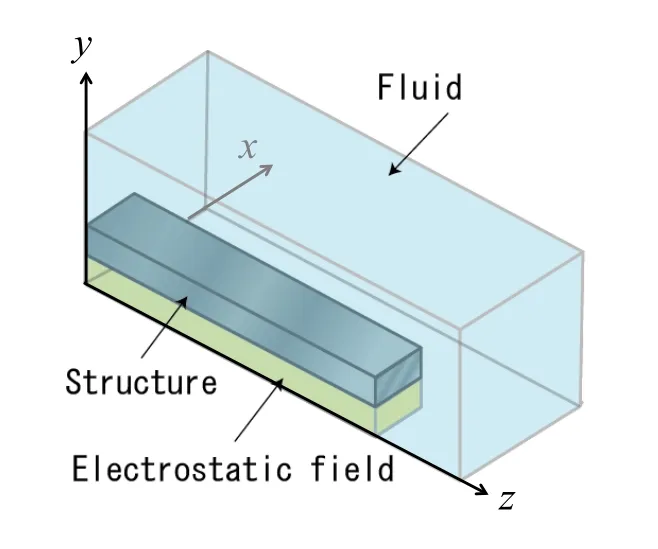
Figure 6:Schematic view of the analysis domains.
4.2 Material properties
The material properties of air(26 degrees C)are the mass density ρf=1.18×10⁻³g/cm3and the viscosityµf=1.82×10⁻⁴g/(cm sec).The dielectric constants of air and vacuum are 8.859×10⁻¹²F/m and 8.854×10⁻¹²F/m,respectively.The thin membrane thicker than 1µm has the mass density equivalent to that of the bulk material.Therefore,the mass density of the beam ρsis assumed to be that of the bulk material of Si 2328 kg/m3.The Poisson’s ratio of the thin membrane is such small[Namazu,Tanaka,and Inoue(2007)]that it is negligible in the structural analysis.Therefore,the Poisson’s ratio of the beam νsis assumed to be 0.The Young’s modulus of the membrane is different from that of the bulk material due to the scale effect[Sato,Yoshida,Ando,Shikida,and Kawabata(1998)].Therefore,the Young’s modulus of the beamEsis determined as follows:
The natural frequency of the first bending mode of the beamf(1)nis measured experimentally from its free vibration in vacuum as 4320Hz.The theoretical solution ofunder the assumption of the Euler-Bernoulli beam is given as

whereIis the second moment of the sectional area of the beam.Substituting the value off(1)nfrom the experiment into Eq.(36),Esis given as 184.2 GPa,which is consistent with that in the previous study[Sato,Yoshida,Ando,Shikida,and Kawabata(1998)].
4.3 Numerical setup
The schematic view of the analysis domains is shown in Fig.6.As shown in this figure,the present problem is assumed to be symmetry with respect to they-zplane.For the structural domain,the beam’s end is fixed atz=0.For the fluid domain,the boundary conditions are no-slip aty=0 and the structural surface,while traction free in the other outer boundaries.For the domain of the electrostatic field,0 V andVg[V]are imposed on the boundaries aty=0 and the structural surface,respectively.The mesh for the structural domain consists of 661 nodes and 240 elements,where the quadratic hexahedral elements are used,the mesh for the fluid domain consists of 5916 nodes and 26698 elements,where the linear tetrahedral elements with the pressure-stabilizing/Pertov-Galerkin (PSPG)method[Tedzduyar,Mittal,Ray,and Shih(1992)]are used,and the mesh for the electrostatic field domain consists of 195 nodes and 480 elements,where the linear tetrahedral elements are used.The time increment Δtis 1 µsec.Note that the diffusion number condition(31)imposes the smaller time increment for the present setup.Therefore,the second level decomposition in Figs.1 and 2 is used in this study.
4.4 Results and discussion
4.4.1Structure-electrostatic interaction analysis
In this section,the vibration of the micro cantilever beam driven by the step electrostatic force in vacuum is analyzed.Fig.7(a)shows the time histories ofvtipfor=3.5V.As shown in this figure,the numerical result from the structure electrostatic interaction analysis is consistent with the experimental result,while the numerical result from the structural analysis is inconsistent with the other results.The vibration period from the structural analysis is constant and equivalent to the natural period of the beam.On the contrary,as shown in Fig.7(b),the vibration period from the structure-electrostatic interaction analysis as well as the experiment is larger than that from the structural analysis for any voltage,and their difference increases as the voltage increases.Similarly,as shown in Fig.7(c),the vibration amplitude from the structure-electrostatic interaction analysis as well as the experiment is larger than that from the structural analysis for any voltage,and their difference increases as the voltage increases.This effect of the structure electrostatic interaction can be explained theoretically as follows:
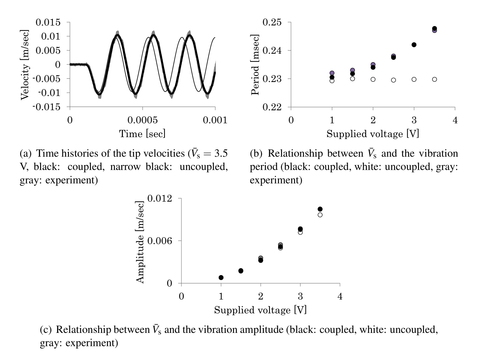
Figure 7:Numerical and experimental results in vacuum.
Let us consider a single-degree-of-freedom system that consists of the massmdriven by the electrostatic forcefand the supporting springk.The equation of motion can be written as
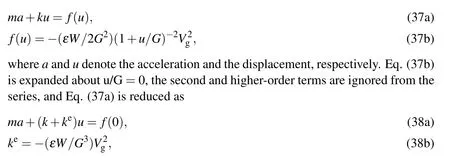

Figure 8:Time histories of the tip velocity in air.The red lines indicate the results from the structure-fluid-electrostatic interaction analyses,the blue lines indicate the results from the structure-fluid interaction analyses,and the grey lines indicate the experimental results.
wherekeis the added stiffness that represents the effect of the structure-electrostatic interaction.As shown in Eq.(38b),keis negative and proportional to the square ofVg.This theoretical result is consistent with the effect of the structure-electrostatic interaction appears in Figs.7(a)–(c).Therefore,the structure-electrostatic interaction analysis as well as the experiment is different from the structural analysis qualitatively as well as quantitatively. It follows from these results that the structure electrostatic interaction analysis is necessary for the accurate prediction for the vibration characteristics of MEMS driven by the electrostatic force in vacuum.
4.4.2Structure-fluid-electrostatic interaction analysis
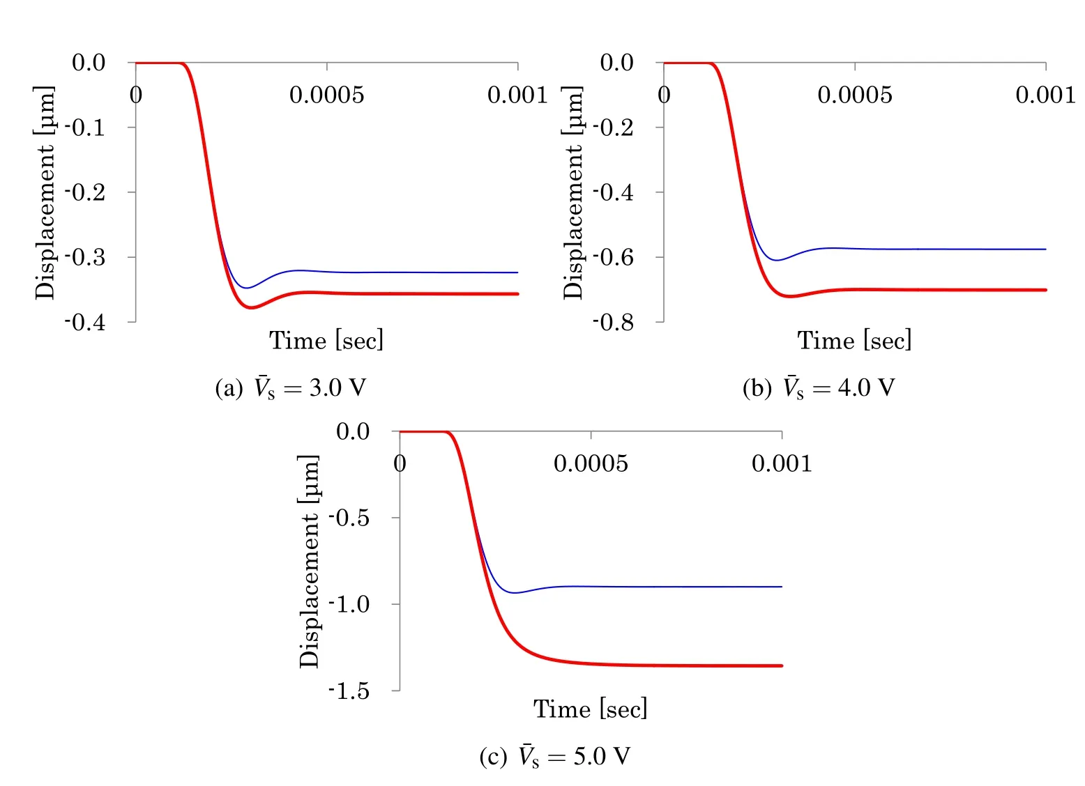
Figure 9:Time histories of the tip displacement in air.The red lines indicate the results from the structure-fluid-electrostatic interaction analyses,and the blue lines indicate the results from the structure-fluid interaction analyses.
In this section,the vibration of the micro cantilever beam driven by the step electrostatic force in air is analyzed Figs.8(a),(b),and(c)show the time histories ofvtipfor¯Vs=3.0V,4.0V,and 5.0V,respectively.It follows from the comparison of these figures with Fig.7(a)that the air damping effect is significant at the present size scale.As shown in these figures,different from the structure-fluid interaction analysis,the numerical results from the structure-fluid-electrostatic interaction analysis are consistent with the experimental results.The vibration period from the structure-fluid interaction analysis is approximately equivalent to the natural period of the beam.On the contrary,the vibration period from the structure-fluid electrostatic interaction analysis as well as the experiment is larger than that from the structure-fluid interaction analysis for any voltage,and their difference increases as the voltage increases.Similarly,the vibration amplitude from the structure fluid-electrostatic interaction analysis as well as the experiment is larger than that from the structure-fluid interaction analysis for any voltage,and their difference increases as the voltage increases.The cause of these phenomena will be explained by the negative added stiffness from the electrostatic field.On the contrary,the following phenomenon cannot be explained by only it:
As shown in Figs.8(a),(b),and(c),in the case of the structure-fluid interaction analysis,the kinematical characteristic of the vibration is underdamping for any voltage.On the contrary,as shown in these figures,in the case of the structure fluid-electrostatic interaction analysis,the kinematical characteristic of the vibration changes from underdamping to overdamping as the voltage increases.This qualitative difference of the vibration characteristic will be caused as follows:
Figs.9(a),(b),and(c)show the time histories ofutipfor=3.0V,4.0V,and 5.0V,respectively,whereutipdenotes the displacement of the deflection at the free end of the beam.As shown in these figures,the magnitude ofutipfrom the structure fluid-electrostatic interaction analysis is larger than that from the structure-fluid interaction analysis due to the negative added stiffness.For example,in the case of=5.0V,the magnitude ofutipat equilibrium from the structure-fluid-electrostatic interaction analysis is 1.36µm,while that from the structure-fluid interaction analysis is 0.899µm.The former is about 1.5 larger than the latter.Since the magnitude of damping of the flow in the narrow gap is proportional to the inverse of a power of the actual gap length,the damping in the structure-fluid-electrostatic interaction is larger than that in the structure-fluid interaction.Therefore,the structure fluid-electrostatic interaction analysis is different from the structure-fluid interaction analysis qualitatively as well as quantitatively.It follows from these results that the structure-fluid-electrostatic interaction analysis is necessary for the accurate prediction of the vibration characteristics of MEMS driven by the electrostatic force in air.
5 Conclusion
The structure-fluid-electrostatic interaction is one of typical phenomena in MEMS due to the scale effect.Therefore,it should be carefully taken into account during the design process in order to predict the vibration characteristics.In this study,the hierarchal decomposition was proposed in order to solve it efficiently.Based on the multilevel decomposition hierarchy that characterized system in each level as a two- field coupled system,the proposed decomposition consisted of the partitioning and the splitting in a hierarchal way as follows:
In the first level,the structure-fluid-electrostatic interaction was partitioned into the structure-fluid interaction and the electrostatic field using the iterative staggered method.In the second level,the structure-fluid interaction was split into the structure-fluid velocity field and the fluid pressure field using the projection method.In the third level,the structure-fluid velocity field was partitioned into the structural velocity field and the fluid velocity field using the explicit method.
The proposed decomposition was implemented using the finite element method,where the three-dimension and the structural large deformation were taken into account because of the significant finite-size effect on the drag force,and was applied to the micro cantilever beam driven by the step electrostatic force in vacuum and air.
It was shown from the comparisons among the numerical and experimental results that(a)the numerical results from the proposed method taking into account the full interaction showed the good agreements with the experimental results,(b)the interaction effects were the negative added stiffness,the significant air damping,and their coupling, and (c) they affected on the vibration characteristics of the micro cantilever beam qualitatively as well as quantitatively.
Acknowledgement:This work was supported by JSPS KAKENHI 26390133.
Badia,S.;Quaini,A.;Quarteroni,A.(2008a):Splitting methods based on algebraic factorization for fluid-structure interaction.SIAM Journal on Scientific Computing,vol.30,no.4,pp.1778–1805.
Badia,S.;Quaini,A.;Quarteroni,A.(2008b):Modular vs.non-modular preconditioners for fluid-structure systems with large added-mass effect.Computer Methods in Applied Mechanics and Engineering,vol.197,pp.4216–4232.
Beskok,A.;Karniadakis,G.E.;Trimmer,W.(1996):Rarefaction and compressibility effects in gas microflows.Journal of Fluids Engineering,vol.118,no.3,pp.448–456.
Chang,K.M.;Lee,S.C.;Li,S.H.(2002):Squeeze film damping effect on a MEMS torsion mirror.Journal of Micromechanics and Microengineering,vol.12,pp.556–561.
Cho,Y.H.;Pisano,A.P.;Howe,R.T.(1994):Viscous damping model for laterally oscillating microstructures.Journal of Microelectromechanical Systems,vol.3,pp.81–87.
De,S.K.;Aluru,N.R.(2004):Full-Lagrangian schemes for dynamic analysis of electrostatic MEMS.Journal of Microelectromechanical Systems,vol.13,pp.737–758.
De,S.K.;Aluru,N.R.(2006):Complex nonlinear oscillations in electrostatically actuated microstructures.Journal of Microelectromechanical Systems,vol.15,pp.355–369.
De,S.K.;Aluru,N.R.(2006):Coupling of hierarchical fluid models with electrostatic and mechanical models for the dynamic analysis of MEMS.Journal of Micromechanics and Microengineering,vol.16,pp.1705–1719.
Felippa,C.A.;Park,K.C.;Farhat,C.(2001):Partitioned analysis of coupled mechanical system.Computer Methods in Applied Mechanics and Engineering,vol.190,pp.3247–3270.
Fernandez,M.A.;Moubachir,M.(2005):A Newton method using exact jacobians for solving fluid-structure coupling.Computers and Structures,vol.83,pp.127–142.
Fernandez,M.A.;Gerbeau,J.-F.;Grandmont,C.(2007):A projection semi implicit scheme for the coupling of an elastic structure with an incompressible fluid.International Journal for Numerical Methods in Engineering,vol.69,pp.794–821.
Gad-el-Hak,M.(1999):The fluid mechanics of microdevices–The Freeman scholar lecture.Journal of Fluids Engineering,vol.121,pp.5–33.
Ghosh,R.;Mukherjee,S.(2009):Fully Lagrangian modeling of dynamics of MEMS with thin beams – part 2: damped vibrations.Journal of Applied Mechanics,vol.76,pp.051008-1(9 pages).
Ghosh,R.;Mukherjee,S.(2009):Fully Lagrangian modeling of dynamics of MEMS with thin beams–part 1:undamped vibrations.Journal of Applied Mechanics,vol.76,pp.051007-1(10 pages).
Guermond,J.L.;Minev,P.;Shen,J.(2006):An overview of projection methods for incompressible flows.Computer Methods in Applied Mechanics and Engineering,vol.195,pp.6011–6045.
Heil,M.(2004):An efficient solver for the fully coupled solution of large displacement fluid-structure interaction problems.Computer Methods in Applied Mechanics and Engineering,vol.193,pp.1–23.
Hughes,T.J.R.;Liu,W.K.;Zimmerman,T.K.(1981):Lagrangian–Eulerian finite element formulation for incompressible viscous flows.Computer Methods in Applied Mechanics and Engineering,vol.29,pp.329–349.
Hu,Y.J.;Yang,J.;Kitipornchai,S.(2010):Pull-in analysis of electrostatically actuated curved micro-beams with large deformation.Smart Materials and Structures,vol.19,pp.065030(9 pages).
Idelsohn,S.R.;Del Pin,F.;Rossi,R.;Onate,E.(2009):Fluid-structure interaction problems with strong added-mass effect.International Journal for Numerical Methods in Engineering,vol.80,pp.1261–1294.
Ishihara,D.;Kanei,S.;Yoshimura,S.;Horie,T.(2008):Efficient parallel analysis of shell-fluid interaction problem by using monolithic method based on consistent pressure Poisson equation.Journal of Computational Science and Technology,vol.2,pp.185–196.
Ishihara,D.;Horie,T.(2014):A projection method for the monolithic interaction system of an incompressible fluid and a structure using a new algebraic splitting.Computer Modeling in Engineering and Sciences,vol.101,no.6,pp.421–440.
Ishihara,D.;Horie,T.;Denda,M.(2009):A two-dimensional computational study on the fluid-structure interaction cause of wing pitch changes in dipteran flapping flight.The Journal of Experimental Biology,vol.212,pp.1–10.
Ishihara,D.;Horie,T.;Niho,T.(2014):An experimental and three-dimensional computational study on the aerodynamic contribution to the passive pitching motion of flapping wings in hovering flies.Bioinspiration and Biomimetics,vol.9,pp.046009(23 pages).
Ishihara,D.;Yoshimura,S.(2005):A monolithic approach for interaction of incompressible viscous fluid and an elastic body based on fluid pressure Poisson equation.International Journal for Numerical Methods in Engineering,vol.64,pp.167–203.
Lee,J.W.;Tung,R.;Raman,A.;Sumali,H.;Sullivan,J.P.(2009):Squeezefilm damping of flexible microcantilevers at low ambient pressures:theory and experiment.Journal of Micromechanics and Microengineering,vol.19,pp.105029(14 pages).
Li,G.;Aluru,N.R.(2001):Linear,nonlinear and mixed-regime analysis of electrostatic MEMS.Sensors and Actuators A,vol.91,pp.278–291.
Mihara,T.;Ikehara,T.;Konno,M.;Murakami,S.;Maeda,R.;Fukawa,T.;Kimura,M.(2011):Design,fabrication,and evaluation of highly sensitive compact chemical sensor system employing a micro cantilever array and a preconcentrator.Sensors and Materials,vol.23,pp.397–417.
Minami,S.;Yoshimura,S.(2010):Performance evaluation of nonlinear algorithms with line-search for partitioned coupling techniques for fluid–structure interactions.International Journal for Numerical Methods in Fluids,vol.64,pp.1129–1147.
Mukherjee,S.;Telukunta,S.;Mukherjee,Y.X.(2005):BEM modeling of damping forces on MEMS with thin plates.Engineering Analysis with Boundary Elements,vol.29,pp.1000–1007.
Namazu,T.;Tanaka,M.;Inoue,S.(2007):A simple determination method of inplane Poisson’s ratio for MEMS materials by means of on-chip pure bending test.Proceedings of 20th IEEE International Conference on Micro Electro Mechanical Systems,pp.235–238.
Rochus,V.;Gutschmidt,S.;Cardona,A.;Geuzaine,C.(2012):Electromechano-fluidic modeling of Microsystems using finite elements.IEEE Transactions on Magnetics,vol.48,no.2,pp.355–358.
Rochus,V.;Rixen,D.J.;Golinval,J.-C.(2005):Electrostatic coupling of MEMS structures:transient simulations and dynamic pull-in.Nonlinear Analysis,vol.63,pp.e1619–e1633.
Rochus,V.;Rixen,D.J.;Golinval,J.-C.(2006):Monolithic modeling of electro-mechanical coupling in micro-structures.International Journal for Numerical Methods in Engineering,vol.65,pp.461–493.
Rochus,V.;Rixen,D.;Golinval,J.C.(2007):Non-con firming element for accurate modeling of MEMS.Finite Elements in Analysis and Design,vol.43,pp.49–756.
Rugonyi,S.;Bathe,K.J.(2001):On finite element analysis of fluid flows fully coupled with structural interactions.Computer Modeling in Engineering and Sciences,vol.2,pp.195–212.
Sato,K.;Yoshida,T.;Ando,T.;Shikida,M.;Kawabata,T.(1998):Tensile testing of silicon film having different crystallographic orientations carried out on a silicon chip.Sensors and Actuators A,vol.70,pp.148–152.
Shi,F.;Ramesh,P.;Mukherjee,S.(1996):Dynamic analysis of micro-electromechanical systems.International Journal for Numerical Methods in Engineering,vol.39,pp.4119–4139.
Tedzduyar,T.E.;Mittal,S.;Ray,S.E.;Shih,R.(1992):Incompressible flow computations with stabilized bilinear and linear equal-order-interpolation velocity pressure elements.Computer Methods in Applied Mechanics and Engineering,vol.95,pp.221–242.
Xu,K.;Sun,L.(2011):Multi- field coupled dynamics for micro plate.International Journal of Applied Electromagnetics and Mechanics,vol.35,pp.201–229.
Ye,W.;Wang,X.;Hemmert,W.;Freeman,D.;White,J.(2003):Air damping in laterally oscillating microresonators:a numerical and experimental study.Journal of Microelectromechanical Systems,vol.12,no.5,pp.557–566.
Zhang,Q.;Hisada,T.(2001):Analysis of fluid-structure interaction problems with structural buckling and large domain changes by ALE finite element methods.Computer Methods in Applied Mechanics and Engineering,vol.190,pp.6341–6357.
Zhang,Q.;Hisada,T.(2004):Studies of the strong coupling and weak coupling methods in FSI analysis.International Journal for Numerical Methods in Engineering,vol.60,pp.2013–2029.
1Department of Mechanical Systems Engineering,Kyushu Institute of Technology,680-4 Kawazu,Iizuka,Fukuoka 820-8502,Japan
2Correspondence author.E-mail:ishihara@mse.kyutech.ac.jp
3Center for Microelectronic System(CMS),Kyushu Institute of Technology,680-4 Kawazu,Iizuka,Fukuoka 820-8502,Japan
 Computer Modeling In Engineering&Sciences2015年30期
- Computer Modeling In Engineering&Sciences的其它文章
- Solving a Class of PDEs by a Local Reproducing Kernel Method with An Adaptive Residual Subsampling Technique
- Analytical and FE Modeling of FG Beams Based on A Re fined Shear Deformable Beam Theory for Static and Dynamic Analyses of FG Beams With Thermoelastic Coupling
