Conjugate Heat Transfer in Uniformly Heated Enclosure Filled with Micropolar Fluid
H.Imtiazand F.M.Mahfouz
Conjugate Heat Transfer in Uniformly Heated Enclosure Filled with Micropolar Fluid
H.Imtiaz1and F.M.Mahfouz2
This paper investigates numerically the conjugate heat transfer in a concentric enclosure that is formed between two concentric cylinders and filled with micropolar fluid.The wall of inner cylinder is considerably thick,while the wall of outer cylinder is very thin.The inner cylinder is heated from inner side through constant heat flux,whereas the outer cylinder is cooled and maintained at constant temperature.The induced buoyancy driven flow and associated conjugate heat transfer are predicted numerically by solving flow and energy governing equations considering a combination of finite difference and Fourier spectral methods.The study investigates the effect of controlling parameters on both flow and thermal fields,keeping focus on inner wall temperature.The controlling parameters are Rayleigh number Ra,dimensionless thickness of inner wall,inner cylinder fluid thermal conductivity ratio Kr,and material parameters of micropolar fluid(λ,B and D).The study shows that the steady dimensionless mean inner wall temperaturedecreases with increase in Kr and Ra,and decrease in the vortex viscosity D.The study also shows that the increase in thickness of inner wall at Kr<1 leads to increase in steady.While in case of Kr>1,for a given value of Ra and D,assumes maximum value at certain thickness of inner wall.In general,the study demonstrates that,for same geometrical and flow parameters,is more in case of micropolar fluids as compared to Newtonian fluids.
Conjugate heat transfer,concentric annulus,thermal conductivity ratio,Rayleigh number,micropolar fluid,natural convection.
1 Introduction
Free convection in a concentric enclosure constitutes an important heat transfer problem for engineering purposes.Its possible applications include nuclear reactors,food processing devices,underground power transmission,etc.Numerous investigations have been done pertinent to free convection in concentric enclosure.Most of the studies done by Kuehn and Goldstein(1976),Mahfouz(2012),Abbott(1964),Grigull and Hauf(1966),Mack and Bishop(1968),Kuehn and Goldstein(1978),Walton(1980),Farouk and Güceri(1982),Tsui and Trembaly(1983),Mizushima,Hayashi and Adachi(2001),ElSherbiny and Moussa(2004),Alshahrani and Zeitoun(2005),Padilla,Campregher and Silveira-Neto(2006),Hassan and Al-lateef(2007),El-Sherbiny and Moussa(2004),Ha and Kim(2004),Oztop,Zhao and Bo(2009)and Oztop and Abu-Nada(2008)considered heating the inner wall of the enclosure at constant wall temperature,while few studies conducted by Kumar(1988),Castrejon and Spalding(1988),Yoo(2004),Yoo(2003)and Ho,Lin and Chen(1987)considered heating the inner wall at constant heat fl ux.The results of these studies,however,were limited to enclosures that contain Newtonian fluids and thus were not suitable to give predictions in case of heterogeneous mixture that include liquid crystal,exotic lubricants,animal blood,suspension solutions,etc.Such mixtures are used in chemical,food and pharmaceutical industries.In order to predict the behavior of such mixtures,Eringen(1964,1972)introduced the theory of micropolar fluids.This theory includes modifications of conventional governing equations of Newtonian fluid flow to account for microscopic effects.These modifications require solving an additional transport equation representing the principle of conservation of local angular momentum.
The study of both flow and heat convection problems related to micropolar fluids up to 1973 was compiled by Ariman and Turk(1973).Gorla and Takhar(1987)investigated the free convection boundary layer flow of micropolar fluid past slender bodies.Gorla(1988)studied the effects of buoyancy force on forced convection along a vertical cylinder.Hassanien and Gorla(1990)analyzed the mixed convection boundary layer flow of a micropolar fluid near a stagnation point on a horizontal cylinder.They showed that micropolar fluids display drag reduction and reduced surface heat transfer rate as compared to Newtonian fluids.Bhattacharyya and Pop(1996)investigated free convection from cylinders of elliptic cross-section in micropolar fluids.Mahfouz(2003)investigated the transient and steady free convection from isothermal cylindrical tubes placed in infinite medium of micropolar fluid.Mahfouz(2004)analyzed the natural convection from an elliptic tube with major axis horizontal and placed in a micropolar fluid.Molla,Hossain and Paul(2006)investigated the free convection laminar boundary layer flow from a horizontal circular cylinder with a uniform surface temperature in presence of heat generation.Recently,Mahfouz(2013a)studied free convection within an eccentric annulus filled with micropolar fluid,heated at constant wall temperature.Mahfouz(2013b)also studied buoyancy driven micropolar fluid flow within uniformly heated eccentric annulus.
It can be seen from literature studies that it has been the common practice of authors to ignore the thickness of wall through which heat is conducted to the fluid.Therefore,in these studies,thermal boundary conditions are employed on the interface between the wall and fluid,and thus the energy equation is solved alone in fluid domain.Such practice leads to erroneous heat transfer results in case of high pressure industrial applications(core of nuclear reactor is example)in which significant wall thickness is necessary for safe operation.These applications require coupling the solution of convective heat transfer in the fluid domain with the solution of conduction heat transfer in the solid wall and this practice is named as conjugate heat transfer.
The only study which considered the conjugate heat transfer in the annulus filled with micropolar fluid was done by Imtiaz and Mahfouz(2014).In that study,the authors investigated conjugate heat transfer in concentric annulus by heating the annulus at constant wall temperature.It seems,to the best of our knowledge,that the problem of conjugate heat transfer in a uniformly heated concentric annulus fi lled with micropolar fl uid has not yet been studied,which provides motivation to analyze this particular problem.For industrial applications related to concentric annulus heated from its inner wall at constant heat flux,the aim is to eliminate any chance of unwanted overheating of inner wall of the annulus.Therefore,this study,besides investigating the flow and thermal fields within the annulus,also considers the effect of various controlling parameters on the steady inner wall temperature.These controlling parameters are Rayleigh number Ra,thickness of inner wall,inner wall-fluid thermal conductivity ratio Kr,and material parameters of micropolar fl uid(λ,B and D).The previous studies by Mahfouz(2003,2004,2013a,2013b)and Imtiaz and Mahfouz(2014)have indicated that the most important material parameter of micropolar fluid is the vortex viscosity D of the fluid.Thus,this study focuses on the effect of D on flow and thermal fields.
2 Problem description and governing equations
Fig.1 shows geometry of problem under consideration,which is annular space between two concentric cylinders.This annular space contains micropolar fluid in it.The inner thick cylinder is heated from its inner side through constant heat flux,while the outer very thin cylinder is cooled and kept at constant low temperatureTo.The fluid motion is assumed two dimensional and laminar,and the density of fluid is assumed constant except for buoyancy term which varies according to Boussinesq approximation.The governing equations of motion and energy can be written in cylindrical coordinates in form of vorticity,stream function,microrotation and temperature.
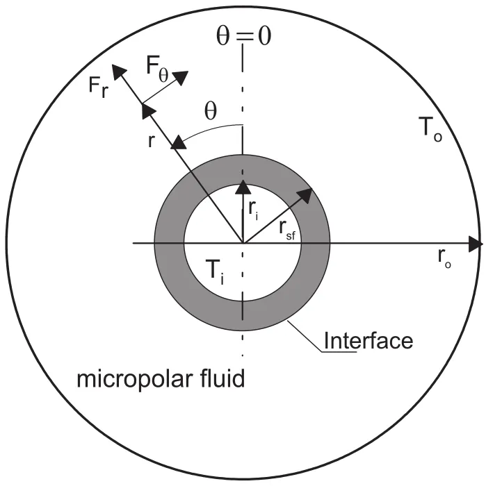
Figure 1:Physical domain and coordinate system

Energy equation for fluid part

Energy equation for solid part

where

σ is the component of microrotation vector,whose direction of rotation is in ther−θ plane.j,γ andKvare the material parameters of micropolar fluid.The radial and tangential components of buoyancy force areFr=ρgβ(T−To)cosθ andFθ=−ρgβ(T−To)sinθ,respectively.
In this study,the following dimensionless parameters will be used

Using the above dimensionless parameters and the modified polar coordinates(ξ=lnR,θ),equations(1)–(5)can be written in following form:
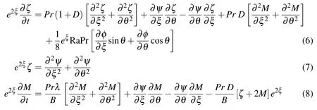
Energy equation for fluid in the annulus

Energy equation for solid inner wall

wherePr=ν/α is the Prandtl number andis the Rayleigh number.The definition ofis found in study conducted by Ho,Lin and Chen(1987)and thus is used here for validation study.
2.1 Initial and boundary condition
The inner cylinder surface is assumed to be heated instantaneously at timet=0,while the fluid around the cylinder is assumed initially at rest and at the ambient temperature(i.e.φ=0).The boundary conditions are based on no-slip,impermeability on the inner and outer walls.These conditions can be expressed as

At solid-fluid interface,ξ =ξsf

For micro-rotation,M,no spin conditions are assumed at fluid adjacent walls,that is

where Kr=ks/kf.
2.2 Method of solution
The technique used to solve the governing equations(6–10)along with the boundary conditions equation(11)is based on using the Fourier Spectral Method.In this technique,the stream function,vorticity,microrotation and temperature are approximated as Fourier series expansions.The same approach is used by Mahfouz(2004)and Badr(1985).The dimensionless stream function,vorticity,microrotation and temperature are approximated as:
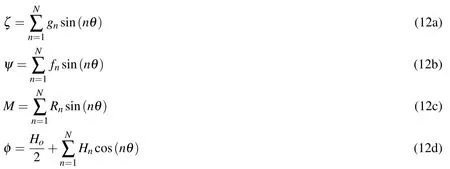
wherefn,gn,Rn,HoandHnare the Fourier coefficients and all are functions of ξ and t.The values of dimensionless stream function,vorticity,microrotation and temperatureinequations(6–10)arereplacedbytheirrespectiveFouriercoefficients in relations(12a–12d).The integration of the resulting equations(after multiplying each side at a time by 1,sin(nθ),cos(nθ))with respect to θ between the limits 0 and 2π results in the following set of differential equations:
In the fluid side
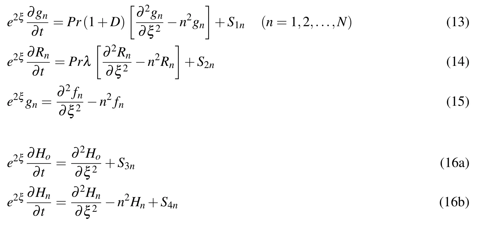
And in the solid side

whereS1n,S2n,S3nandS4nare all easily identifiable functions of ξ andt.The boundary conditions for all the functions presented in equations(13–17)are obtained from boundary conditions(11)and can be expressed as
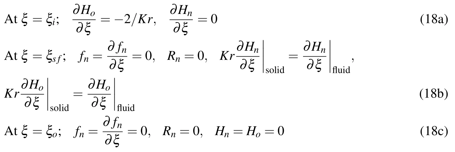
Integrating both sides of equation(15)with respect to ξ(after multiplying bye−nξ)from ξ = ξsfto ξ = ξoand using the boundary conditions represented by equation(18)gives the following integral conditions

The above integral condition is used for calculating the values of the functiongnon outer surface of solid part of the annulus,whereasgnon outer thin wall of the annulus is calculated by solving equation(15)directly.The details of the method of solution and numerical treatment are more or less similar to those explained in Badr(1985)and Badr and Dennis(1985).
Once the temperature distribution is determined,the heat transfer parameters can be estimated.In case of CHF,the total heat transfer rate from the inner wall is known and the most important parameter from practical point of view is the inner surface temperature of the inner wall,φI,which should be inspected to avoid the unwanted over heating of the surface.The value of φIis calculated from equation(12d)and the mean dimensionless temperature of the inner wall is then calculated as:

The steady local heat flux distribution along the outer wall can be expressed in terms of heat flux ratio as,qr=qo/qiwhereqiis the constant heat flux applied to the inner surface of inner wall.
3 Results and discussion
Many numerical experiments have been performed to solve the governing equations along with the boundary conditions for investigating the effect of controlling parameters on both flow and thermal fields.These controlling parameters are Ra,Pr,Rr(=ro/ri),Kr(=ks/kf),Rs(=rsf/ri)and material parameters of micropolar fl uid(λ,B and D).The study considers Ra up to 105,a range of Rs from 1.1 to 1.5,and a range of Kr from 0.5 to 100.The range of dimensionless material parameter D is taken from 0 to 10.The other parameters Rr,λ,B and Pr are fixed at 2.6,1,1,and 0.7,respectively.
Before generating the numerical results,the validity of the numerical technique has been first assessed by comparing the present results with the results in the studies conducted by Yoo(2004,2003)and Ho,Lin and Chen(1987).Due to absence of experimental and numerical results for the problem considered,numerical results are validated by comparing the present results with the numerical results for the case of concentric annulus that contains Newtonian fluid and has zero inner wall thickness.These comparisons are presented in Figs.2 and 3.Fig.2 shows good qualitative agreement between present distributions of streamlines and isotherms with the corresponding numerical results of Yoo(2004).While Fig.3 shows very good quantitative agreement between the present results for local inner wall tem-perature distribution and the corresponding numerical results of Ho,Lin and Chen(1987).
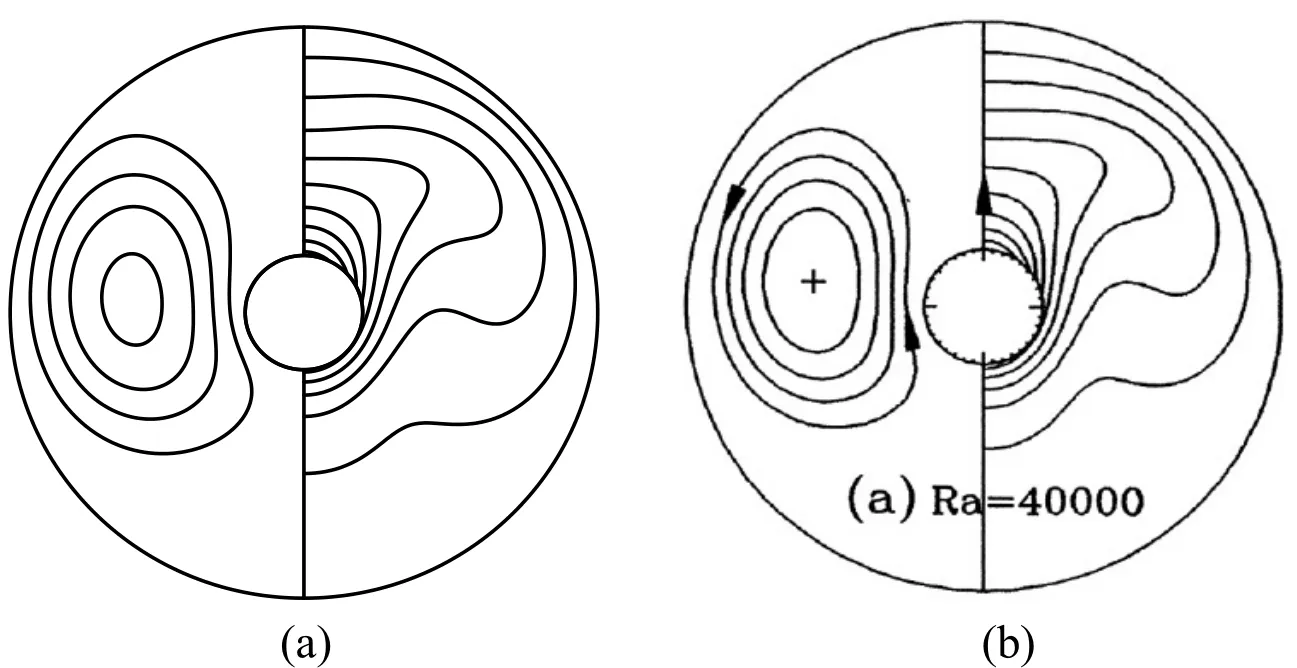
Figure 2:Steady streamlines(left half)and isotherms(right half)at RaL=4x10⁴,Rr=5.0,Rs=1 and Kr=1(a)Present and(b)Yoo(2004)
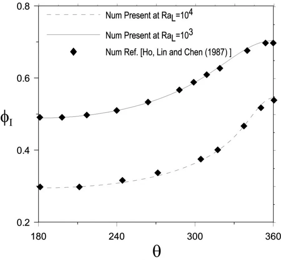
Figure 3:Dimensionless inner wall temperature and comparison with Ho,Lin and Chen(1987)results at Rr=2.6,Rs=1,and Kr=1
After validating the numerical method,the effect of controlling parameters on both fl ow and thermal fi elds is considered.Fig.4 shows the effect of micropolar param-eter D on the steady distributions of streamlines and isotherms for the case of Ra=105,Kr=1.0,Rs=1.5 and atD=0,1,3,and 5.
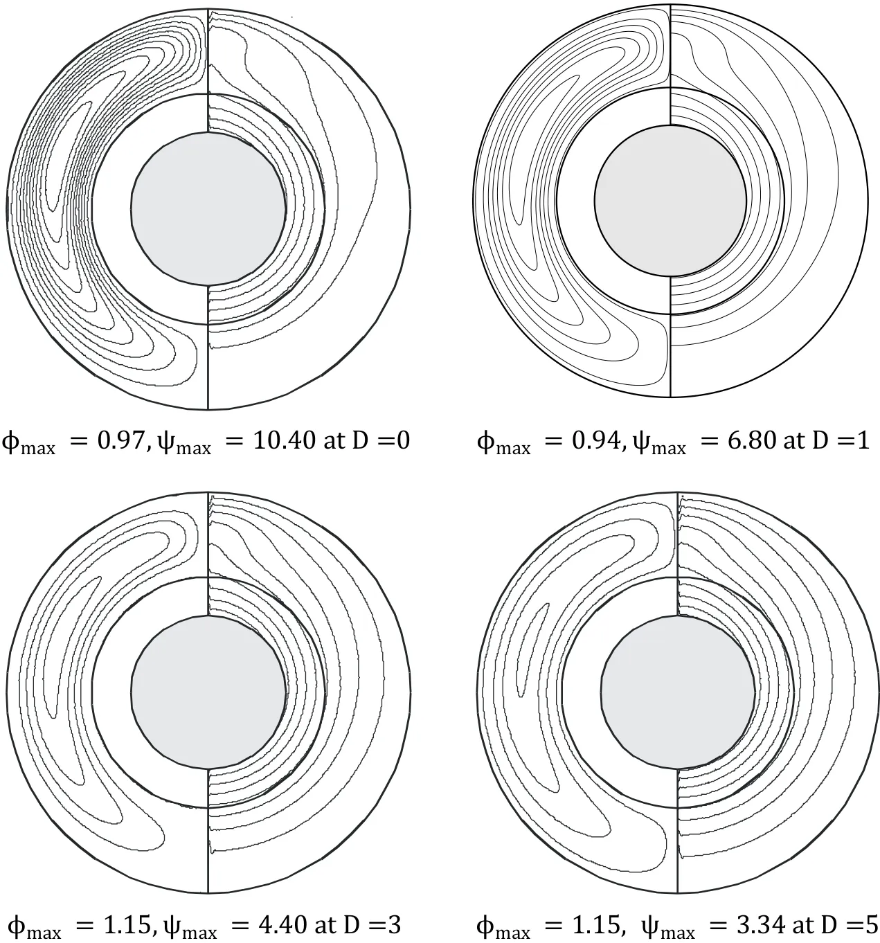
Figure 4:Right side is streamlines∆ψ =1.0 and left side is isotherms∆φ=0.1 for the case of Ra=105,Rs=1.5 at D=0,1,3,and 5
The figure shows only one half of each field due to vertical symmetry of the problem.Right half of the figure shows the streamlines,while left half presents the isotherms.It can be seen that the value of ψmaxreduces from 10.40 to 3.34 as D increases from 0 to 5.This indicates that the intensity of convection current decreases with the increase in D.Low convection currents make heat process dominated by conduction and increase the total thermal resistance,which leads to increase in the temperature levels as well as increase in maximum temperature(φmaxincreases from 0.97 to 1.15 as D increases from 0 to 5)as can be seen in the figure.It can also be noted from the isotherms that the domination of conduction makes the thermal plume diminish and with the increase in D,the isotherms tend to concentric circles.Fig.5 shows the effect of D on vorticity and microrotation for the case of Ra=105,Kr=1.0,Rs=1.5 and at D=0,1,3,and 5.The maximum magnitude of vorticity and microrotation observed in flow can be represented by ζmaxandMmaxrespectively.Fig.5 shows that ζmaxchanges from 460 to 8.4 as D changes from 0 to 5.This decrease in vorticity can be attributed to the decrease in convection currents intensity as D increases.Fig.5 also shows thatMmaxincreases from 0 to 8.4 as D increases from 0 to 5.It concludes that although maximum vorticity decreases with increase in D,the maximum spin velocity represented by microrotation increases.
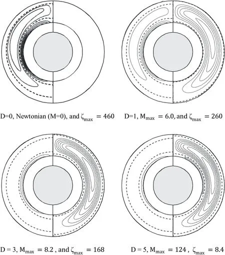
Figure 5:Steady patterns of steady equi-vorticity(right)and equi-microroatation(left)in case of Ra=105,Rs=1.5,and at D=0,1,3 and 5
The decrease of convectionintensity as a result of reductionof velocity components can be inferred from Figs.6 and 7.These figures also show that as D increases,the radial velocity component along θ =0°(Fig.6)and tangential velocity component along the line of θ =90°(Fig.7),clearly reduces.
The local interface temperature Φsfdistribution along the fluid side of the inner wall for the same case is shown in Fig.8.The figure shows that the high surface temperature in the top region of thermal plume(around θ =0°)decreases monotonically along the surface towards almost stagnant and isothermal lower region(around θ =180°).The figure also shows clearly that as D increases,the local interface temperature increases at the corresponding points.This is due to the increase in fluid effective viscosity,which weakens the convection currents and increases the convection thermal resistance.
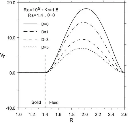
Figure 6:The steady dimensionless radial velocity distribution along θ =0° at different values of D
Fig.9 shows the local heat flux distribution along the outer wall for the same case.It can be seen that the heat flux is high around the stagnation point created due to impact of upward induced flow with the outer wall,while it assumes lower values at almost stagnant lower region.The already heated upward flow coming along the sides of inner wall,when stagnates at the cold outer wall around θ=0°,high temperature gradient is created and in turn high heat flux is produced.After stagnation and during its downward motion along the outer wall,the flow temperature continuously reduces,resulting in continuous decrease in temperature gradient that results in continuous decrease in the heat flux along the wall.In the upper region,the convection currents work together with conduction to increase the heat flux,while in the lower region the convection currents,though are weak,work opposite to the heat conduction,which reduces the heat flux.Therefore,as D increases the intensity of convection currents relatively decreases and as a result the heat flux decreases in the upper region,while the opposite occurs in the lower region as can be seen in the figure.
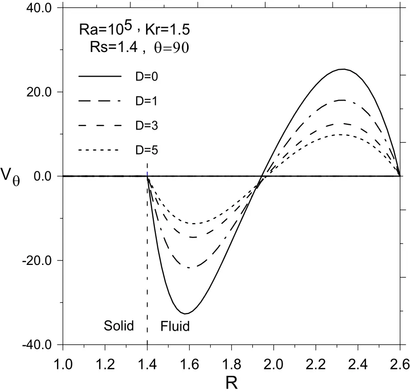
Figure 7:The steady dimensionless tangential velocity distribution along θ =90°at different values of D
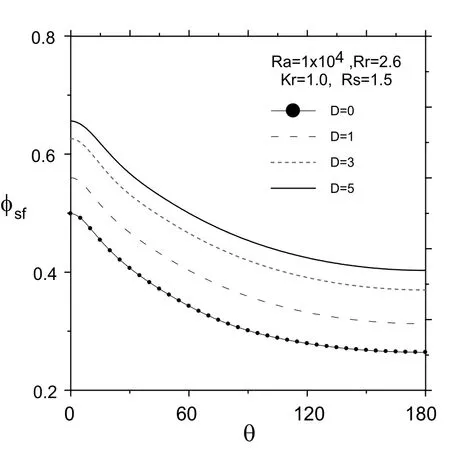
Figure 8:The steady dimensionless temperature distribution along the interface at different values of D
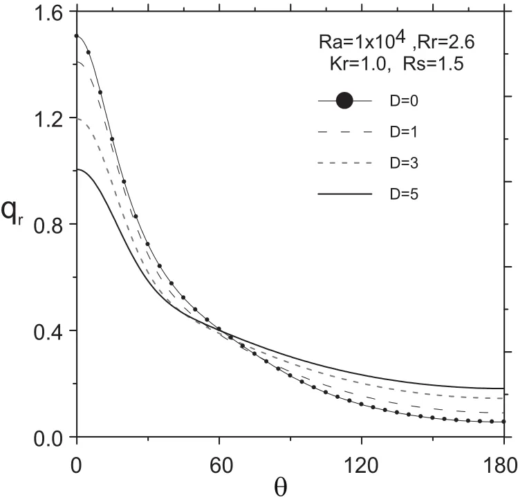
Figure 9:The steady heat flux ratio distribution along the outer wall at different values of D
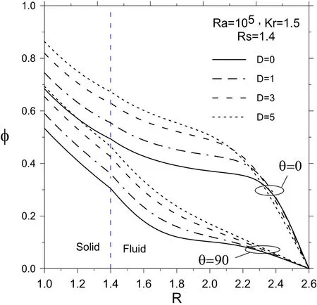
Figure 10:The steady dimensionless temperature distribution along radial directions θ =0°,θ =90° at different values of D
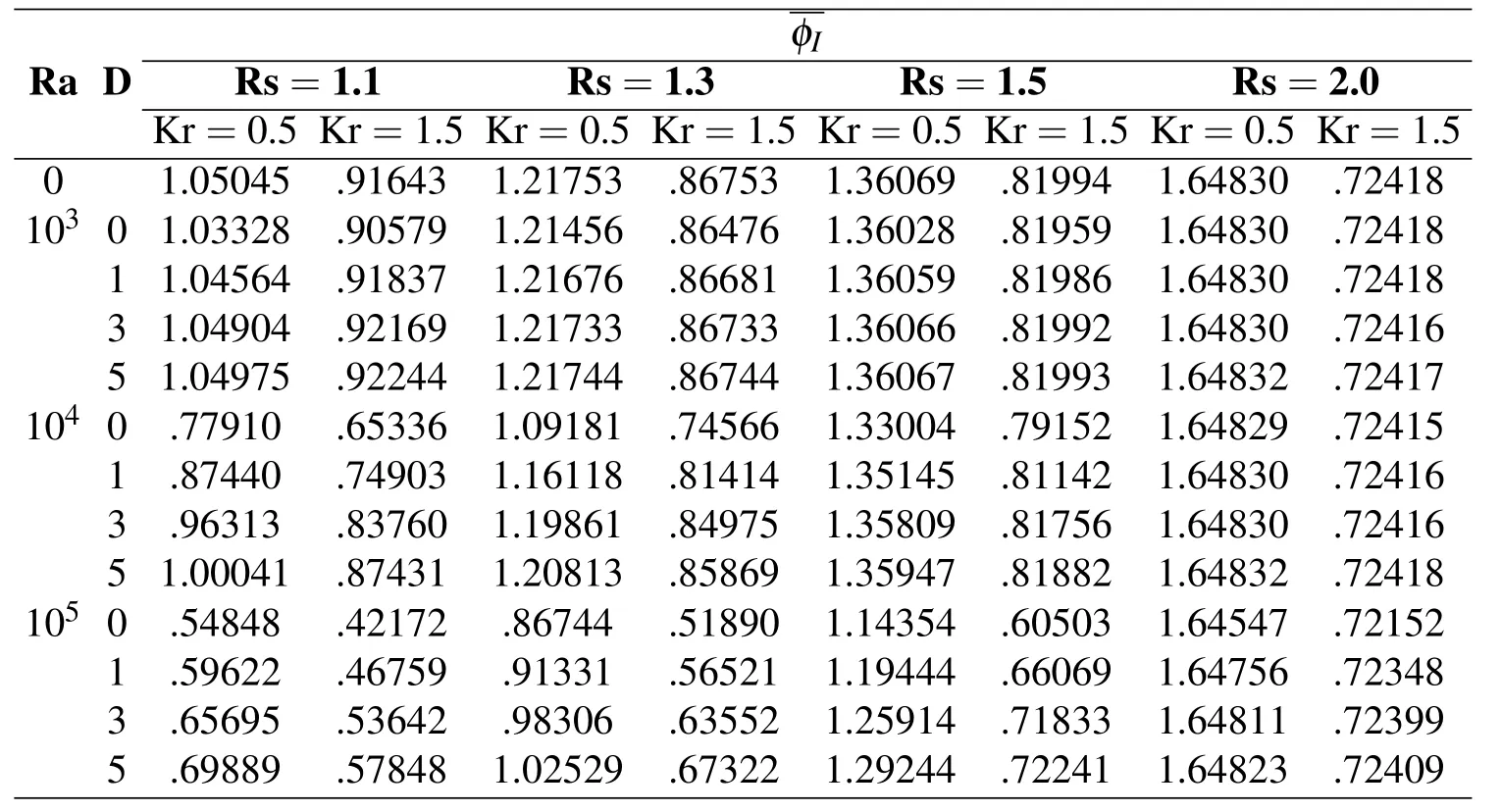
Table 1:Effect of Ra,Rs and D on φIat Kr=0.5 and Kr=1.5
Fig.10 shows the dimensionless temperature distribution in the radial directions θ =0°,θ =90°and at different values of D.It can be inferred from the figure that temperature levels in both solid wall and fluid domain increase as D increases.The increase in D generally weakens the convection currents and thus increases the thermal resistance,which in turn increases the temperature levels.
The effect of D and other controlling parameters on the mean dimensionless inner wall temperature φIis listed in Tab.1 at Kr=0.5 and Kr=1.5.Quick inspection of Tab.1 shows that in general,the value ofgets smaller in case of higher conductivity of inner wall.The table also shows thatincreases as D increases,whereas it decreases with the increase in Ra.It should be noted,as explained in Mahfouz(2012,2013b),that the decrease inwith the increase in Ra does not mean that the mean inner wall temperature(Ts)itself decreases.It only indicates that mean dimensionless inner wall temperaturedecreases.The table clearly shows that the effect of D onbecomes more signi fi cant in case of high Ra and small Rs.In latter cases,the convection currents play important role in heat transfer process.As Rs increases the fluid domain gets narrower,and thus the convection currents get weaker(even at high Ra).The weakening of convection currents makes the thermal resistance mainly dominated by conduction.The domination of conduction on thermal resistance at large Rs is reflected in the table,where it can be observed that there is almost no effect of both Ra and D onat relatively large values of Rs(for all values of Ra and D at Rs=2,
The effect of inner wall thickness in terms of Rs oncan also be observed in Tab.1.The table shows thatincreases as Rs increases for all values of Ra and D,when the inner wall thermal conductivity is lower than that of the fl uid,i.e.Kr=0.5.This is due to the signi fi cant increase in total conduction resistance.In case of Kr>1,the table shows that in pure conduction regime(Ra=0)and conduction dominated regimes Ra≤103as Rs increasesdecreases due to decrease in the total thermal resistance.While in case of convection dominated regime Ra=105,the table shows that as Rs increasesincreases due to relative increase in the total thermalresistance.Itshouldalsobenotedforconvectiondominatedregimethat the convection resistance is very small for low values of Rs.This resistance increases as Rs increases with a rate more than that of the decrease of total conduction resistance,which leads to relative increase of total thermal resistance.

Figure 11:The steady mean dimensionless temperature of inner wall at Ra=104,Kr=1.5 and at different values of D
In case of moderate Ra(Ra=104),Tab.1 shows that as Rs increases,increases and then decreases again,indicating the existence of maximum value ofat certain Rs.To delineate this point further,some detailed calculations were carried out at Ra=104and Kr=1.5 with a step of 0.1 for Rs,and the results are presented in Fig.11.The fi gure clearly shows thatis maximum at certain value of Rs.This maximum value for,as can be observed in the fi gure,is D dependent;as D increases the value of Rs,at whichis maximum,decreases.Existence of maximumat certain Rs can be explained based on the fact thatis controlled by two resistances,namely,the conduction(in both solid wall and fl uid)and convection resistances.The effect of Rs on these two resistances is different.As Rs increases,the conduction resistance decreases(since Kr>1),while the convection resistance increases.The opposite effect of Rs on the two resistances creates a maximumat a certain value of Rs for every value of D.
Tab.2 shows detailed results for the effect of Kr onat different values of Ra and D,whereas Rs is fi xed at 1.3.It can be seen thatdecreases with the increase in Kr.This decrease inis faster in the lower range of Kr.For instance:70%reduction inis observed at Ra=105and D=1,when Kr increases from 0.25 to 10,in which 65%of this reduction occurs as Kr increases from 0.25 to 2.0,while only 5%reduction occurs,when Kr changes from 2.0 to 10.Moreover,the table shows that the decrease inas Kr increases becomes more observable because Ra increases and/or D decreases.
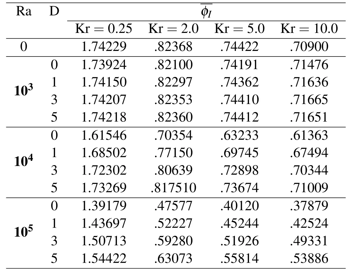
Table 2:Effect of Kr on φIat Rs=1.3 and at different values of Ra and D
The effect of Kr on φ along radial directions(θ =0°and θ =90°)is shown in Fig.12.It can be inferred from the figure that the mean temperature of inner wall(at R=1)is higher for small values of Kr due to the higher conduction resistance in this case.The figure also shows that the temperature gradient within inner wall is greater in case of small Kr and gets smaller as Kr increases,reaching almost zero gradient at high Kr.It can also be observed that Kr has negligible effect on φ in the fl uid domain.
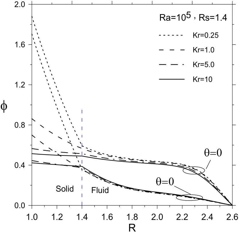
Figure 12:The steady dimensionless temperature distribution along radial directions θ =0°,θ =90° at different values of Kr
4 Conclusion
This paper investigates numerically the conjugate heat transfer in a concentric enclosure that is formed between two concentric cylinders having radius ratio of 2.6 and filled with micropolar fluid.The wall of inner cylinder has considerable thickness,while the wall of outer cylinder is very thin.The inner cylinder is heated from inner side through constant heat flux,whereas the outer cylinder is cooled and maintained at constant temperature.The induced buoyancy driven flow and associated conjugate heat transfer are predicted numerically by solving flow and energy governing equations considering a combination of finite difference and Fourier spectral methods.The study investigates the effect of controlling parameters on both flow and thermal fields with focus on inner wall temperature.The controlling parameters are Rayleigh number Ra,dimensionless thickness of inner wall,inner cylinder-fluid thermal conductivity ratio Kr,and material parameter of micropolar fl uid D.Ra is considered up to 105,Rs is considered from 1 to 2,Kr is considered between 0.25 and 10,while D is considered up to 5.The study shows that steady mean inner wall dimensionless temperaturedecreases as Kr or Ra increases,whereas it decreases as D decreases.Generally,the study demonstrates that,for same geometrical and fl ow parameters,is more in case of micropolar fl uids as compared to Newtonian fl uids.The study also shows that with the increase in thickness of inner wall at Kr<1,the steadyincreases.While in case of Kr> 1,the steadyassumes maximum value at certain thickness of inner wall in a moder-ate range of Ra.This critical thickness is dependent on value of D,where as D increases the critical thickness decreases.This study will be helpful in optimizing the design parameters(such as thickness and thermal conductivity of inner wall)of concentric annuli filled with either Newtonian or micropolar fluid associated with high pressure industrial applications.
Nomenclature
roRadius of outer cylinder
riInner radius of inner cylinder
rsfOuter radius of inner cylinder
Rr Radius ratio(=rsf/ri)
L Difference of radius(=ro−ri)
Vr,VθDimensionless radial and tangential components of velocity
Ra Rayleigh number(=8gβ(ri)4qi/kfνα)
RaLRayleigh number based on L(=gβ(ro−ri)4qi/kfνα)
Rs Dimensionless outer radius of inner wall cylinder(=rsf/ri)
Kr Inner cylinder-fluid thermal conductivity ratio(=ks/kf)
ksThermal conductivity of inner thick wall cylinder
kfThermal conductivity of fluid in heated enclosure
g Gravitational acceleration
Kv,D Vortex viscosity and dimensionless vortex viscosity
ToTemperature of outer thin wall cylinder
j,B Micro-inertia density and dimensionless micro-inertia density
FrRadial component of buoyancy force(=ρgβ(T−To)cosθ)
FθTangential component of buoyancy force(=−ρgβ(T−To)sinθ)
t Dimensionless time
T Temperature
Pr Prandtl number(=ν/α)
N Dimensionless microrotation
r Dimensionless radial coordinate(r/ri)
gn,fn,Rn, Fourier coefficients
Ho,Hn
qrHeat flux ratio
qoHeat rejected from outer cylinder
qiHeat flux applied to the inner surface of inner wall
Greek symbols
ζ0ζ Vorticity and dimensionless vorticity
ψ0,ψ Stream function and dimensionless stream function
φ Dimensionless temperature
β Coefficient of thermal expansion
ρ Density
τ Time
θ Angular coordinate
αsThermal diffusivity of inner cylinder
α Thermal diffusivity of fluid between concentric cylinders
γ,λ Spin gradient viscosity and dimensionless spin gradient viscosity
ν Kinematics viscosity
ξ Dimensionless logarithmic coordinate(=lnR)
Kuehn,H.;Goldstein,R.J.(1976):An experimental and theoretical study of natural convection in the annulus between horizontal concentric cylinders.J.Fluid Mech.,vol.74,pp.695–719.
Mahfouz,F.M.(2012):Heat convection within an eccentric annulus heated at either constant wall temperature or constant heat flux.ASME,J.Heat Transfer,vol.134,no.8,pp.082502(1–9).
Abbott,M.R.(1964):A numerical method for solving the equations of natural convection in narrow concentric cylindrical annulus with a horizontal axis.Q.J.Mech.Appl.Math.,vol.17,no.4,pp.471–481.
Grigull,U.;Hauf,W.(1966):Natural convection in horizontal cylindrical annuli.Proc.,3rd Int.Heat Transfer Conf.2,pp.182–195.
Mack,L.R.;Bishop,E.H.(1968):Natural convection between horizontal concentric cylinders for low Rayleigh numbers.Q.J.Mech.Appl.Math.,vol.21,pp.223–241.
Kuehn,H.;Goldstein,R.J.(1978):An experimental study of natural convection heat transfer in concentric and eccentric horizontal cylindrical annuli.ASME,J.Heat Transfer,vol.100,pp.635–640.
Walton,I.C.(1980):The stability of free convection in a horizontal cylindrical annulus.Q.J.Mech.Appl.Math.,vol.33,pp.125–139.
Farouk,B.;Güceri,S.I.(1982):Laminar and turbulent natural convection in the annulus between horizontal concentric cylinders.J.Heat Transfer,vol.104,pp.631–636.
Tsui,Y.T.;Trembaly,B.(1983):On transient natural convection heat transfer in the annulus between concentric horizontal cylinders with isothermal surfaces,Int.J.Heat and Mass Transfer,vol.27,no.1,pp.103–111.
Mizushima,J.;Hayashi,S.;Adachi,T.(2001):Transitions of natural convection in a horizontal annulus.Int.J.Heat and Mass Transfer,vol.44,pp.1249–1257.
ElSherbiny,S.M.;Moussa,A.R.(2004):Effects of Prandtl number on natural convection in horizontal annular cavities.Alexandria Eng.J.,vol.43,pp.561–576.
Alshahrani,D.;Zeitoun,O.(2005):Natural convection in horizontal cylindrical annuli.Alexandria Eng.J.,vol.44,pp.813–823.
Padilla,E.L.M.;Campregher,R.;Silveira-Neto,A.(2006):Numerical analysis of the natural convection in horizontal annuli at low and moderate Ra.Engenharia Térmica(Thermal Engineering),vol.5,pp.58–65.
Hassan,A.K.;Al-lateef,J.M.A.(2007):Numerical simulation of two dimensional transient natural convection heat transfer from isothermal horizontal cylindrical.J.Eng.,vol.13,no.2,pp.1429–1444.
El-Sherbiny,S.M.;Moussa,A.R.(2004):Natural convection in air layers between horizontal concentric isothermal cylinders.Alexandria Eng.J.,vol.43,pp.297–311.
Ha,M.Y.;Kim,J.G.(2004):Numerical simulation of natural convection in annuli with internal fins.KSME Int.J.,vol.18,no.4,pp.718–730.
Oztop,H.F.;Zhao,Z.;Bo,Y.(2009):Fluid flow due to combined convection in lid-driven enclosure having a circular body.Int.J.of Heat and Fluid Flow,vol.30,pp.886–901.
Oztop,H.F.;Abu-Nada,E.(2008):Numerical study of natural convection in partially heated rectangular enclosures filled with nanofluids.Int.J.Heat and Fluid Flow,vol.29(5),pp.1326–1336.
Kumar,R.(1988):Study of natural convection in horizontal annuli,Int.J.Heat Mass Transfer,vol.31,no.6,pp.1137–1148.
Castrejon,A.;Spalding,D.B.(1988):An experimental and theoretical study of transient free-convection flow between horizontal concentric cylinders.Int.J.Heat Mass Transfer,vol.31,no.2,pp.273–284.
Yoo,J.S.(2004):Flow pattern transition of natural convection in a horizontal annulus with constant heat flux on the inner wall.Int.J.Numer.Methods Heat Fluid Flow,vol.15,no.7,pp.698–709.
Yoo,J.S.(2003):Dual free-convective flows in a horizontal annulus with a constant heat flux wall.Int.J.Heat Mass Transfer,vol.46,pp.2499–2503.
Ho,C.J.;Lin,Y.H.;Chen,T.C.(1987):A numerical study of natural convection in concentric and eccentric horizontal cylindrical annuli with mixed boundary conditions.Int.J.Heat and Fluid Flow,vol.10,no.1,pp.40–47.
Eringen,A.C.(1964):Simple Microfluids,Int.J.Eng.Sci.,pp.205–217.
Eringen,A.C.(1972):Theory of thermomicrofluids.J.Math.Anal.Appl.,vol.38,pp.480–496.
Ariman,T.;Turk,M.A.(1973):Sylvester ND,Microcontinuum fluid mechanics a review.Int.J.Eng.Sci.,vol.11,pp.905–930.
Gorla,R.S.R.;Takhar,H.S.(1987):Free convection boundary layer flow of a Micropolar fluid past slender bodies.Int.J.Eng.Sci.,vol.25,no.8,pp.949–962.
Gorla,R.S.R.(1988):Buoyancy effects on the boundary layer flow of a micropolar fluid along a vertical cylinder.Int.J.Eng.Sci.,vol.26,no.8,pp.883–892.
Hassanien,I.A.;Gorla,R.S.R.(1990):Mixed convection boundary layer flow of a micropolar fluid near a stagnation point on a horizontal cylinder.Int.J.Eng.Sci.,vol.28,no.2,pp.153–161.
Bhattacharyya,S.;Pop,I.(1996):Free convection from cylinders of elliptic cross-section in micropolar fluids.Int.J.Eng.Sci.,vol.34,no.2,pp.1301-1310.
Mahfouz,F.M.(2003):Transient free convection from a horizontal cylinder placed in a Micropolar fluid.Heat and Mass Transfer,vol.39,pp.455–462.
Mahfouz,F.M.(2004):Natural convection from an elliptic tube with major axis horizontal and placed in a Micropolar fluid.Int.J.Heat Mass Transfer,vol.47,pp.1413–1422.
Molla,M.M.;Hossain,M.A.;Paul,M.C.(2006):Natural convection flow from an isothermal horizontal circular cylinder in presence of heat generation.Int.J.Eng.Sci.,vol.44,no.2,pp.949–958.
Mahfouz,F.M.(2013):Numerical simulation of free convection within an eccentric annulus filled with micropolar fluid using spectral method.Appl.Math.Comput.,vol.219,pp.5397–5409.
Mahfouz,F.M.(2013):Numerical prediction of buoyancy driven micropolar fluid fl ow within uniformly heated eccentric annulus.Appl.Math.Modell.,vol.37,pp.6037–6054.
Imtiaz,H.;Mahfouz,F.M.(2014):Conjugate heat transfer within a concentric annulus filled with micropolar fluid.Heat and Mass Transfer,vol.50,pp.457–468.
Badr,H.M.(1985):Heat transfer in transient buoyancy driven flow adjacent to a horizontal rod.Int.J.Heat Mass Transfer,vol.30,pp.1990–2012.
Badr,H.M.;Dennis,S.R.(1985):Time-dependent viscous flow past an impulsively started rotating and translating circular cylinder.J.Fluid Mech.,vol.158,pp.447–488.
1Dept.of Mechanical Engineering,UET Taxila,Pakistan
2Dept.of Mechanical Power,Menoufia University,Egypt
 Computer Modeling In Engineering&Sciences2015年27期
- Computer Modeling In Engineering&Sciences的其它文章
- Large Deformation Hyper-Elastic Modeling for Nonlinear Dynamic Analysis of Two Dimensional Functionally Graded Domains Using the Meshless Local Petrov-Galerkin(MLPG)Method
- Dynamic Response Analysis of the Fractional-Order System of MEMS Viscometer
- A Metamodel-Based Global Algorithm for Mixed-Integer Nonlinear Optimization and the Application in Fuel Cell Vehicle Design
