
Aerodynamic Performance of Dragonfly Wing with Well-designed Corrugated Section in Gliding Flight
2015-12-18 06:52ZilongZhangYajunYinZhengZhongandHongxiaoZhao
Zilong Zhang,Yajun Yin,Zheng Zhong,3 and Hongxiao Zhao
Aerodynamic Performance of Dragonfly Wing with Well-designed Corrugated Section in Gliding Flight
Zilong Zhang1,Yajun Yin2,Zheng Zhong1,3and Hongxiao Zhao1
Dragonflies possess the highly corrugated wings which distinguish from the ordinary airfoils.To unlock the secrets of the dramatic flight ability of dragonflies,it will be of great significance to investigate the aerodynamic contribution of the corrugations.In this paper,a group of corrugated airfoils were specially designed based on the geometrical characteristics of a typical dragonfly wing.The two-dimensional Navier-Stokes equations were solved using the finite volume method,and the coefficients of lift and drag of the studied airfoils were calculated and compared with those of a flat airfoil and a NACA0008 airfoil.The obtained numerical results illustrated that well-designed corrugated airfoils can enhance the lift-drag ratio in the condition of steady flow and maintain the steadiness of the flow field at low Reynolds numbers(500-12000).To approach the optimized state,corrugation amplitude could be considered as a key parameter to describe the irregularities of the corrugated wings.These results will inspire the design of MAVs.
Dragonfly,corrugation,low Reynolds number,CFD,MAV.
1 Introduction
Dragonflies possess dramatic flight ability,especially the amazing maneuverability and flight endurance observed during their trans-oceanic migrations with miraculous distance[Hobson,Anderson,Soto and Wassenaar(2012)],for which their wings play an important role.Unlike ordinary engineered airfoils,dragonfly wings are highly corrugated and act as a light structure,which could enhance the spanwise stiffness,and reduce the membrane stresses in the wings[Rees(1975a)].
The objectofourarticle isto answersuch a question:whetherthe corrugationshave a positive effect on aerodynamic performance of dragonfly wings?Moreover,can acorrugated airfoil be artificially designed to have better aerodynamic performance than a flat airfoil or NACA0008 airfoil under low Reynolds number conditions?
The aerodynamic effect of corrugations was originally measured on pleated models or real insect wings.By testing scale models in a fluid flow channel filled with 45%aqueous sucrose solution,Rees(1975b)concluded that the corrugations have no aerodynamic significance.Similar results were also found from the model experiments in a wind tunnel by Newman et al.(1977)and Rudolph(1977).Newman et al.(1977)stated that the major contribution to the lift enhancement came from some morphological features on the surface of the wing,which are much smaller than corrugations in length scale.Rudolph(1977)conjectured that the only advantage of corrugated airfoils was the delay of flow separation and the avoidance of abrupt stalling at a big angle of attack.On the contrary,Buckholz(1986)found that the corrugations would increase the lift of dragonfly wing by testing pleated wing model(Re=1500).Thereafter,Wakeling and Ellington(1997)confirmed that the enhanced lift of dragonflies was mainly attributed to the corrugations(Re=700−2400).After making detail flow measurements(Re=34000),Hu and Tamai(2008)proposed a mechanism for the enhanced lift of a corrugated wing that the protruding corners promote the transition of separated shear-layer flow from laminar to turbulent.Okamoto et al.(1996)proved that the pleated models are better than the plate model at all angles of attack by conducting experiments on airfoils with various sections.Furthermore,Kesel(2000)pointed out that the corrugations innate to nature are finely tuned in order to achieve a good aerodynamic performance,based on his experimental measurements on pleated models whose geometric parameters were extracted from a wing of dragon fly(Aeshna cyanea).
Recently,CFD methods provide effective numerical tools for researchers in this field.Levy and Seifert(2010)proved that the corrugated airfoil outperformed the traditional streamlined airfoil by conducting 2D numerical analysis based on the finite volume method(Re=6000).Meng and Sun(2013)obtained the conclusion that the corrugations change the lift and the drag very slightly by conducting 3D simulations(Re=200−2400).Vargas et al.(2008)found that corrugated airfoils enhance the lift at higher Reynolds number(Re=10000)and reduce the lift at lower Reynolds numbers(Re=500,1000 and 5000)based on their calculations by the immersed boundary method.
To summarize,researchershave perceived basic aerodynamic characteristicsofcorrugated wings.Nevertheless,there is still no consensus on whether corrugated airfoils perform better than ordinary engineered airfoils.In order to comprehensively understand the inherent fluid dynamical mechanisms behind the complex phenomena of corrugated airfoils,a group of corrugated airfoils with gradually changing sections were specially designed based on the geometrical characteristics of a typi-cal dragonfly wing.The two-dimensional Navier-Stokes equations were solved by the finite volume method,and the coefficients of lift and drag of the above airfoils were calculated and compared with those of a flat airfoil and a NACA0008 airfoil.Some appealing results were obtained for corrugations with different geometric parameters.
2 Models and Methods
2.1 Geometric models of dragonfly wing
It is effective to capture the flow field of dragonfly wings in gliding flight with 2D models[Levy and Seifert(2010);Vargas,Mittal and Dong(2008)]at low Reynolds numbers(Re=500−12000)since previous experimental studies[Buckholz(1986);Okamoto,Yasuda and Azuma(1996);Kesel(2000)]have found no intrinsic threedimensional effects at such low Reynolds numbers.In our calculations,2D models balance the accuracy and efficiency of the CFD simulation.
The “Profile 2”in Kesel’s paper[Kesel(2000)]is selected as the standard section.The corrugated airfoil with standard section is named as Airfoil-1.00.The shape of Airfoil-1.00 is determined by 43 key points whose locations are defined in an orthogonal coordinate system as:

The maximum corrugation amplitude of Airfoil-1.00 is 7.351%c(see figure 1(a)).Based on the standard section,we create new profiles with a transformation function given as:

where λ is the amplification coefficient of the coordinate y.
Asshown in figure 1(b),we designate 11 corrugated airfoils as Airfoil-1.50,Airfoil-1.35,Airfoil-1.20,Airfoil-1.10,Airfoil-1.00,Airfoil-0.90,Airfoil-0.75,Airfoil-0.60,Airfoil-0.45,Airfoil-0.30 and Airfoil-0.15,each having a unique λ and being of the same chord length c.For example,Airfoil-1.50 is formed by setting λ=1.5,and a flat airfoil with rounded leading and trailing edges is degenerated from the pleated profile when λ=0(denoted as Plate).The thicknesses of the flat airfoil and corrugated airfoils are all 0.02c.Besides,NACA0008 is employed for comparison since its maximum thickness(8%c)is approximate to the maximum corrugation amplitude of Airfoil-1.00(7.351%c).
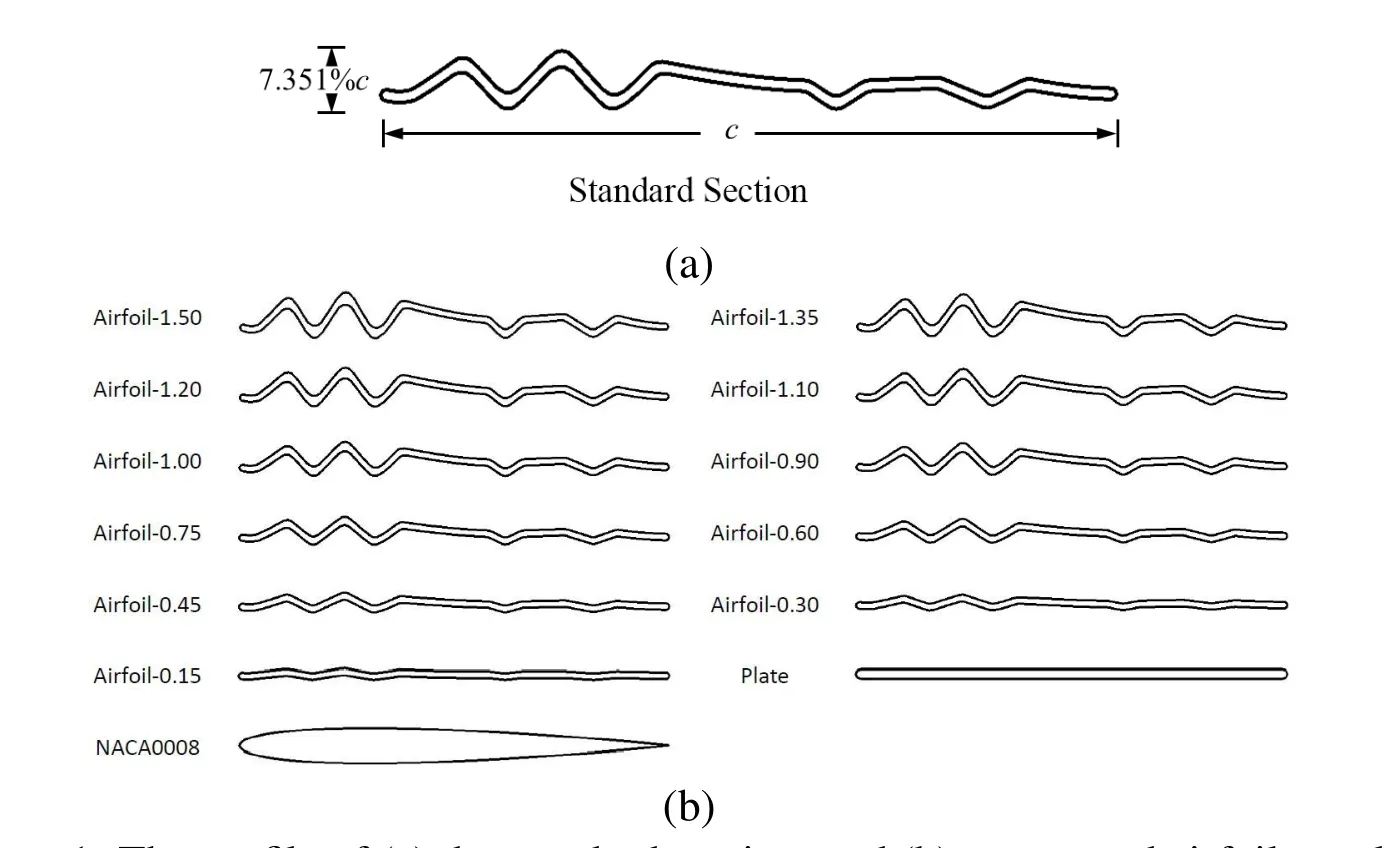
Figure 1:The profile of(a)the standard section,and(b)corrugated airfoils,a plate airfoil and a NACA0008 airfoil.
2.2 Governing equations and solution method
The incompressible 2D Navier-Stokes equations are nondimensionalized,as follows:

where u and v are the nondimensionalized components of flow velocity along x and y directions;p and t are the nondimensionalized pressure and time.Re is the Reynolds number defined as:

where ρ,µ and ν denote respectively the density,the dynamic viscosity coefficient and the kinematic viscosity coefficient of air,while U is the freestream velocity.
The governing equations are solved using commercial solver FLUENT(based on the finite volume method)with SIMPLE algorithm.The model of laminar[Vargas,Mittal,and Dong(2008);Kunz and Kroo(2000)]is also adopted in our calculations.As shown in figure 2,the flow field is simulated by an elliptical area which has a 20c long axis and a 15c short axis to meet the far field condition.The boundary conditions of the airfoil and the flow field are wall and velocity-inlet respectively.The structured grids are applied to the solution domain.

Figure 2:Solution area,boundary conditions and mesh.
The lift and the drag of an airfoil are denoted as Fland Fdrespectively.Then the aerodynamic performance of an airfoil can be described by the lift coefficient Cl=Fl/(0.5ρU2c)and the drag coefficient Cd=Fd/(0.5ρU2c).
2.3 Mesh test and validation
We test the meshes with different resolutions,as shown in figure 3.For Airfoil-1.00,we build 4 types of meshes:100×120(element number along radial and circumference directions,the first layer thickness is 0.0167c),150×180(0.0167c)200×240(0.0125c)and 250×30(0.0125c).Each type of mesh is tested in 9 cases(with the angles of attack taken as 2˚,5˚and 10˚and the Reynolds numbers ranging 500,1000 and 1200 respectively).
In order to display the computational convergence and compare the computational efficiency of different meshes,we define the relative error erand the relative time cost etof each mesh,as follows:

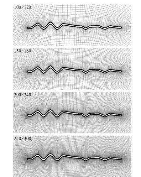
Figure 3:Meshes of Airfoil-1.00 with different resolutions.
where Cliand Cdiare the lift coef ficient and the drag coef ficient calculated from a case for a mesh while Cl∗iand Cd∗iare corresponding results for mesh 250×300(0.0125c);t is the computational time cost using any of above four meshes and t∗is the time cost for mesh 250×300(0.0125c).
Table 1 gives the relative error and the relative time cost of these meshes.Obvious-ly,the relative error reduces as the resolution of the mesh increases,at the cost of more computational time.Considering a balance between accuracy and efficiency of the simulation,we chose 200×240(0.0125c)as the solution of meshes in the subsequent calculation.
Then the computational results of NACA0008 are obtained based on the mesh 200×240(0.0125c)and compared with those of Kunz and Kroo(2000)and Vargas et al.(2008),as tabulated in table 2.This validates that sufficient computational accuracy can be guaranteed using the mesh 200×240(0.0125c)

Table 2:Validation of the computational results of NACA0008 based on the mesh 200×240(0.0125c).
3 Results and discussions
In following calculations,we only study the steady flow for which the fluctuation of the time dependent Cland Cdare less than 10−5.The flow fields around different airfoils described in Section 2.1 are simulated for different Reynolds numbers ranging from 500 to 12000(with an interval of 500)and angles of attack changing from 0˚to 10˚(with an interval of 2˚).
In all figures given in this section,the thick dashed grey line represents the result of NACA0008;the thick solid black line represents that of Airfoil-1.00;the thin solid black line represents that of Plate;and other solid grey lines from thinner to thicker represent those of Airfoil-0.15,Airfoil-0.30,Airfoil-0.45,Airfoil-0.60,Airfoil-0.75,Airfoil-0.90,Airfoil-1.10,Airfoil-1.20,Airfoil-1.35 and Airfoil-1.50 respectively.
3.1 The lift coefficients
As shown in figure 4,the lift coefficients are strongly dependent on the angle of attack and the Reynolds number.For example,at small angle of attack(from 0˚ to 4˚),the curve for Airfoil-1.00 is higher than that of Plate at very low Reynolds numbers.However,it declines rapidly with the increase of the Reynolds number and soon becomes lower than that of Plate.At larger angle of attack(from 6˚to 10˚),the lift coefficient curve of Airfoil-1.00 is always lower than that of Plate.
Meanwhile,we notice that the lift coefficient curves of different corrugated airfoils vary rather widely.This implies that the lift is influenced distinctively by the amplitudes of corrugations.The airfoils with relatively lower corrugation amplitudes(from Airfoil-0.15 to Airfoil-0.60)have obvious advantages in enhancing the lift.A detailed analysis of the flow field structure is given in Section 3.5.
3.2 The drag coefficients
As shown in figure 5,the drag coefficient curves of all the airfoils drop rapidly when the Reynolds number increases from 500 to 2000.Then they decline slowly.The drag coefficient is not influenced distinctly by the amplitudes of corrugations as much as the lift coefficient.As the drag of each airfoil cannot be distinguished from Cd~Re curves,we define the relative drag coefficient C∗das

where CdNACA0008 is the corresponding drag coefficient of NACA0008.
As shown in figure 6,the relative drag coefficient curves increase monotonously with the Reynolds number.Comparing to Plate,Airfoil-1.00 possesses higher C∗d.Nevertheless the C∗dof airfoils with lower corrugation amplitudes(Airfoil-0.15 and Airfoil-0.30)are lower than or nearly the same as that of Plate.
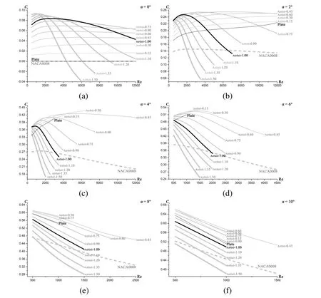
Figure 4:The lift coefficient vs.the Reynolds number at the angle of attack:(a)α=0 ˚,(b)α =2˚,(c)α =4˚,(d)α =6˚,(e)α =8˚,(f)α =10˚.
3.3 lift-drag ratio
The aerodynamic performance of airfoils is evaluated synthetically through the liftdrag ratio Cl/Cd.

Figure 5:The drag coefficient vs.the Reynolds number at the angle of attack α=0˚.
Based on detailed calculations,Meng et al.(2013)and Vargas et al.(2008)demonstrated that comparing to the flat plate,the corrugations may have a negative effect on aerodynamic performance at low Reynolds numbers(Re=500 or 1000).As shown in figure 7,the similar results are also observed from the present calculation of Airfoil-1.00(the same airfoil studied by Vargas et al.(2008)).
However the above predication is not universally valid for other pleated airfoils.In our calculations,the airfoils with smaller corrugation amplitudes with lower corrugation amplitudes enhance Cl/Cd.Comparing to Plate,the increment generated by corrugations is shown as the shadow bands in figure 7;particularly,the average Cl/Cdof Airfoil-0.45 increases about 9%.These observations reveal that the corrugations with well-designed section demonstrate a better aerodynamic performance than that of Plate.
3.4 Steadiness of flow
The flow field around each airfoil varies from steady to unsteady gradually with the increase of the angle of attack and the Reynolds number.We regard the beginning of transition as the shedding(or vibration)of laminar separation bubble which changes the aerodynamic force remarkably.In figures 4 to 7,the thick dashed grey curves are always the longest(the unsteady data are not shown).This indicates that NACA0008 is a better airfoil in maintaining the steadiness of the flow field than Plate and the corrugated airfoils.

Figure 6:The relative drag coefficient vs.the Reynolds number at the angle of attack:(a)α =0˚,(b)α =2˚,(c)α =4˚,(d)α =6˚,(e)α =8˚,(f)α =10˚.
The influence of corrugations on steadiness of flow is nonlinear.In detail,the flow tends to be steady when the airfoil changes from flat to corrugated gradually.After the maximum corrugation amplitude of the airfoil exceeds a critical value,the flow tends to be unsteady.
Airfoil-0.45 and NACA0008 possessidenticalcapabilitiesin maintaining the steadiness of flow field for the Reynolds numbers ranging between 500 and 12000.
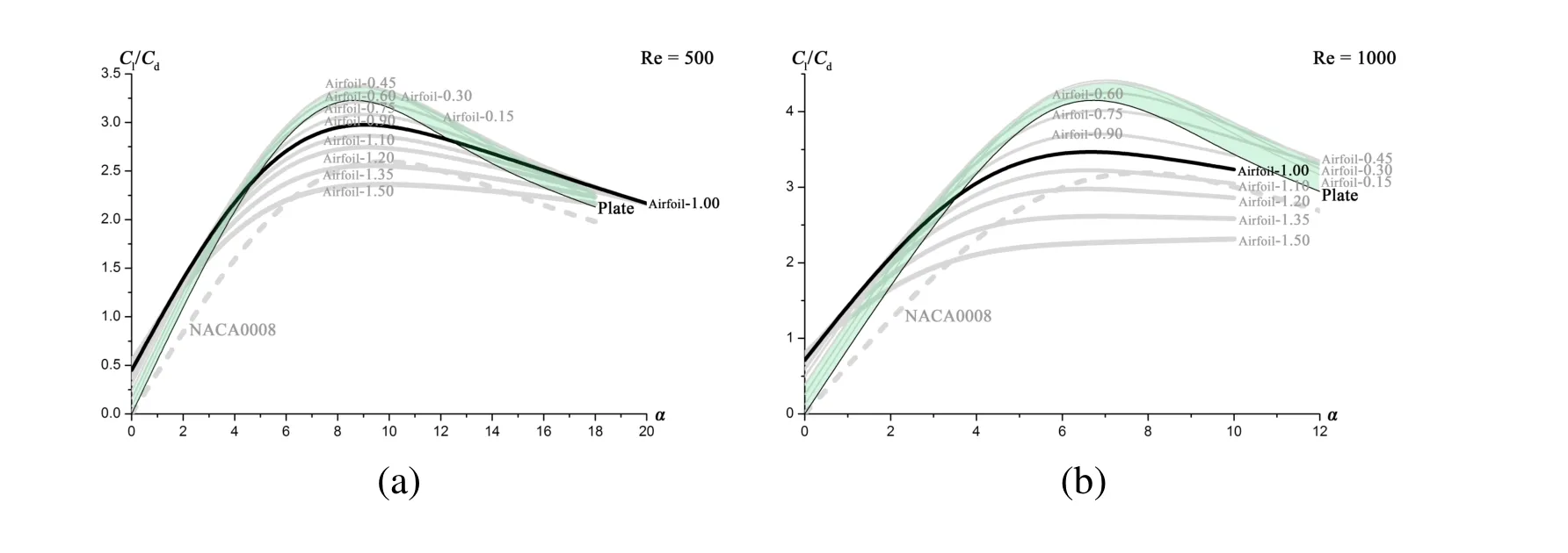
Figure 7:The lift-drag ratio vs.the angle of attack at(a)Re=500;(b)Re=1000.
3.5 Analyses of flow field structures
To reveal the underlying mechanisms of aerodynamic performances described in sections 3.1 to 3.4,the pressure contour and streamline are given here to display the flow field structures.
Figure 8 shows the static pressure contours(numbers in the figure represent the levels of pressure)of the airfoils with different corrugation amplitudes(Plate,Airfoil-0.45 and Airfoil-1.00)at the angle of attack α =6˚and the Reynolds number Re=1000.For Plate(see figure 8(a)),the pressure contours are smooth both on the upper and the lower surfaces;while for Airfoil-0.45(see figure 8(b))with light but distinct corrugations,the pressure of each pleat on the lower surface rises on the windward side but only slightly declines on the leeward so that a larger upward thrust is produced.Thus,the lift is enhanced by the corrugations of airfoils with relative lower corrugation amplitudes.However,this is not true for Airfoil-1.00(see figure 8(c)).For this airfoil with the higher corrugation amplitude,the pressure changes sharply and simultaneously both on the upper and lower surfaces,cancelling out each other and yielding almost no lift enhancement.In short,the different geometries of a corrugated airfoils change the detail structure of pressure field around the airfoil so that the in fluence of the lift is not monotonous.
Figures 9 to 11 depict the streamlines of NACA0008,Airfoil-0.45 and Airfoil-1.00 at the angle of attack α =2˚,with the Reynolds number Re=2000,4000 and 6000.As seen from figure 9,the flow sticks to the surface of NACA0008,with different Reynolds number(2000,4000 and 6000),which is obvious for a streamlined body.And as shown in figure 10,the first separation of flow occurs in the first concave region on the upper surface of Airfoil-0.45 with Re=2000 or 4000,and in the first convex domain on the lower surface with Re=6000.There are 3 to 5 stable separation bubbles filled in the corrugations in the fore part of the airfoil and no separation occurs in the rear part.As a result,such an airfoil as Airfoil-0.45 with relatively lower corrugation amplitudes keeps the flow sticking to a virtual surface as if a streamlined body behaves.

Figure 8:The static pressure contour of(a)Plate,(b)Airfoil-0.45 and(c)Airfoil-1.00 at the angle of attack α =6˚and the Reynolds number Re=1000.
However,for Airfoil-1.00 with higher corrugation amplitude,there are 7 to 9 separation bubbles distributing along the airfoil(see figure 11).Moreover,the bubbles in the rear part of the airfoil spread so quickly that the outer flow departs from the surface of the airfoil.This phenomenon tend to be more obvious with the increase of the Reynolds number.Apparently,the flow field around the airfoil with higher corrugation amplitude possesses quite different structures from those of streamlined body like NACA0008.
In short,the geometry of a corrugated airfoil can be specially designed to tune its flow field as that of a streamlined body.

Figure 9:The streamline of NACA0008 at α =2˚with(a)Re=2000,(b)Re=4000 and(c)Re=6000.

Figure 10:The streamline of Airfoil-0.45 at α =2˚with(a)Re=2000,(b)Re=4000 and(c)Re=6000.
4 Conclusions
Under the low Reynolds number condition of dragonfly flight(500 to 12000),the aerodynamic performance of corrugated airfoil Airfoil-1.00(with the section of the Profile 2 in Kesel’s experiment[Kesel(2000)],τ=7.531%)is not superior to that of a flat plate.However,after amending the amplitude of the corrugations,Airfoil-0.45(with a well designed section,τ=3.389%)shows a remarkable superiority.Comparing to the flat plate in the condition of steady flow,Airfoil-0.45 enhances the lift,reduces the drag(at larger angle of attack)so that it could enhance the average Cl/Cdabout 9%.Meanwhile,it maintains the steadiness of flow as well as the streamline body NACA0008.
In conclusion,a corrugated airfoil with well-designed section can perform better than the plate.To approach an optimized state,the corrugation amplitude could be considered as a key parameter to describe the irregularities of the corrugated wings in steady flow.This result can be a potential inspiration to bionics design for MAVs(micro air vehicles).

Figure 11:The streamline of Airfoil-1.00 at α =2˚with(a)Re=2000,(b)Re=4000 and(c)Re=6000.
Acknowledgement:This work is supported by the National Science Foundation of China(Grant No.11272175)and the Fundamental Research Funds for the Central Universities.
Reference
Buckholz,R.(1986):The functional role of wing corrugations in living systems.Journal of fluids engineering,vol.108,no.1,pp.93-97.
Hobson,K.A.;Anderson,R.C.;Soto,D.X.;Wassenaar,L.I.(2012):Isotopic evidence thatdragonflies(Pantala flavescens)migrating through the Maldivescome from the northern Indian subcontinent.PLoS One,vol.7,no.12 e52594.
Hu,H.;Tamai,M.(2008):Bioinspired Corrugated Airfoil at Low Reynolds Numbers.Journal of Aircraft,vol.45,no.6,pp.2068-2077.
Kesel,A.B.(2000):Aerodynamic characteristics of dragonfly wing sections compared with technical aerofoils.J.Exp.Biol.,vol.203,Pt.20,pp.3125-3135.
Kunz,P.;Kroo,I.(2000):Analysis,design,and testing of airfoils for use at ultralow Reynolds numbers.in Proceedings of a Workshop on Fixed and Flapping Flight at Low Reynolds Numbers,Notre Dame.
Levy,D.E.;Seifert,A.(2010):Parameter study of simplified dragonfly airfoil geometry at Reynolds number of 6000.J.Theor.Biol.,vol.266,no.4,pp.691-702.
Meng,X.G.;Sun,M.(2013):Aerodynamic effects of wing corrugation at gliding flight at low Reynolds numbers.Physics of Fluids,vol.25,no.7,071905.
Newman,B.;Savage,S.;Schouella,D.(1977):Model tests on a wing section of an Aeschna dragonfly.Scale Effects in Animal Locomotion,pp.445-477.
Okamoto,M.;Yasuda,K.;Azuma,A.(1996):Aerodynamic characteristics of
the wings and body of a dragonfly.J.Exp.Biol.,vol.199,Pt.2,pp.281-294.
Rees,C.J.C.(1975):Form and Function in Corrugated Insect Wings.Nature,vol.256,no.5514,pp.200-203.
Rees,C.J.C.(1975):Aerodynamic properties of an insect wing section and a smooth aerofoil compared.Nature,vol.258,no.5531,pp.141-142.
Rudolph,R.(1977):Aerodynamic properties ofLibellula quadrimaculata L.(Anisoptera:Libelludidea),and the flow around smooth and corrugated wing section models during gliding flight.Odonatologica,vol.7pp.49-58.
Vargas,A.;Mittal,R.;Dong,H.(2008):A computational study of the aerody-namic performance of a dragonfly wing section in gliding flight.Bioinspir Biomim,vol.3,no.2,026004.
Wakeling,J.;Ellington,C.(1997):Dragonfly flight.I.Gliding flight and steadystate aerodynamic forces.J.Exp.Biol.,vol.200,Pt.3,pp.543-556.
1Tongji University,Shanghai,China.
2Tsinghua University,Beijing,China.
3Corresponding author.E-mail:zhongk@tongji.edu.cn
 Computer Modeling In Engineering&Sciences2015年33期
- Computer Modeling In Engineering&Sciences的其它文章
- A New Hybrid Uncertain Analysis Method and its Application to Acoustic Field with Random and Interval Parameters
- The Finite Points Approximation to the PDE Problems in Multi-Asset Options
- First Principles Molecular Dynamics Computation on Ionic Transport Properties in Molten Salt Materials