Assessment of Cell-centered and Cell-vertex Finite Volume Approaches for Computation of 2D Structural Dynamics on Arbitrary Quadrilateral Grids
Kazem Hejranfarand Mohammad-Hadi Azampour
Assessment of Cell-centered and Cell-vertex Finite Volume Approaches for Computation of 2D Structural Dynamics on Arbitrary Quadrilateral Grids
Kazem Hejranfar1and Mohammad-Hadi Azampour1
In this study,cell-centered(CC)and cell-vertex(CV) finite volume(FV)approaches are applied and assessed for the simulation of two-dimensional structural dynamics on arbitrary quadrilateral grids.For the calculation of boundary nodes’displacement in the CC FV approach,three methods are employed.The first method is a simple linear regression of displacement of boundary nodes from the displacement of interior cell centers.In the second method,an extrapolation technique is applied for this purpose and,in the third method;the line boundary cell technique is incorporated into the solution algorithm in an explicit manner.To study the effects of grid irregularity on the results of CC and CV FV approaches,different grid types are used ranging from regular square grids to irregular ones,including random perturbations of the grid nodes.A comparison between the CC and CV FV approaches is made in terms of accuracy and performance by simulating some benchmark test cases in structural dynamics on different grid types.The present study demonstrates the suitability of using CC FV approach for the simulation of structural dynamics problems and that the results obtained by careful implementation of the CC FV can be comparable with those of the CV FV.On irregular grids,the CC FV approach employing the extrapolation technique fails to obtain accurate results in the most cases studied,however,two other techniques,namely the linear regression and boundary cell methods provide reasonable results.It is indicated that the CV and CC approaches are equivalent in terms of accuracy and convergence rate on regular grids,though,the CV approach is more efficient in term of computational costs.The results obtained by these two approaches for the problems considered here are in good agreement with the analytical solutions.
Cell-centered and cell-vertex finite volume approaches,Structural dynamics,Arbitrary quadrilateral grids.
1 Introduction
Traditionally, finite element method(FEM)has been the main tool in computational structural dynamics(CSD)[Zienkiewicz&Taylor(1989)]and finite volume method(FVM)in the field of computational fluid dynamics(CFD)[Patanker(1980)].Over the last two decades,new attention has given to FVM to solve problems in structural dynamics.The advantage of FVM over FEM is its local conservation properties which also guaranty the global conservation of variables.Note also that,FEM creates large block-matrices,usually with high condition numbers,and therefore its solution is based on direct solvers while FVM provides diagonally dominant matrices well-suited for iterative solvers and thus,this approach is more efficient in terms of computational costs.As a result,coupling a FV code for the simulation of structural dynamics with a proper CFD code enables engineers to model complicated multiphysics problems in an accurate and efficient manner.
In CSD,similar to CFD,FVM has been classified into two approaches,namely,cell-centered(CC)[Demirdži´c and Martinovi´c(1993);Demirdži´c and Muzaferija(1994);Demirdži´c,Muzaferija,and Peri´c(1997);Fallah(2004,2006);Giannopapa(2004);Greenshields,Weller,and Ivankovic(1999);Hattel and Hansen(1995);Henry and Collins(1993b);Jasak and Weller(2000);Papadakis and Giannopapa(2006);Wheel(1996,1997,1999)]and cell-vertex(CV)approaches[Bailey and Cross(1995);Fryer,Bailey,Cross,and Lai(1991);Lv,Zhao,Huang,Xia,and Su(2007);Oñate,Cervera,and Zienkiewicz(1994);Slone,Bailey,and Cross(2003);Slone,Pericleous,Bailey,Cross,and Bennett(2004);G.A.Taylor(1996);G.A.Taylor,Bailey,and Cross(2003);G.Xia and Lin(2008);G.H.Xia,Zhao,Yeo,and Lv(2007)].The CC FV approach has been the common method in CFD and it can efficiently support most of the CFD codes for the simulation of fluid flows in an accurate and efficient manner.A continuum field which undergoes motion is governed by the Cauchy’s equation which is valid for both structural and fluid dynamics.The fact that the form of equations of Stokes flows is similar to the form of equations of isotropic incompressible linear elastic solids has motivated many researchers to implement CFD methods,developed for the solution of incompressible fluid flows,for modeling displacement in solids.Henry and Collins(1993b)used the SIMPLEC algorithm[Patanker(1980)]for the simulation of small axisymmetric deformation of linear elastic incompressible materials.To prevent volumetric locking in incompressible limit,they used the pressure as an additional variable,similar to the hydrostatic pressure in fluid flows.They later modeled fluid-structure interaction problem of arterial flow by incorporating FLOW3d commercial code[Henry and Collins(1993a)].Similarly,Demirdzic and Muzaferija(1994)used the CC FV approach for the analysis of linear elastic structures and later,they employed the CC FV structure solver with a FV-based flow solver to sim-ulate some fluid-structure interaction problems[Demirdži´c and Muzaferija(1995)].Their method is based on the solution of the integral form of momentum balance equation,where the surface tractions are computed from the surface strains using the constitutive relationship.To compute the surface strains,the displacement of connected nodes is needed in addition to adjacent cell centers.In the boundary regions where Neumann boundary conditions are specified,the boundary fluxes are added to the source term,while the displacement values at the boundary are obtained by extrapolating displacement values from the interior of the solution domain.Wheel(1996)suggested a new boundary condition for the boundary nodes which does not require an extrapolation technique.He used special line and point boundary cells which are able to transfer the applied boundary conditions on to the internal cells.This strategy causes additional degrees of freedom into the analysis.Note that the displacements along boundary edges are automatically calculated as part of the solution procedure.For a benchmark problem studied in Ref.[Wheel(1996)],Wheel showed that the FV method achieves greater accuracy than the FE method.Applying Reissner-Mindlin plate theory,Wheel(1997)analyzed the bending deformation of thick and thin plates and later,he introduced a mixed finite volume formulation for determining the small strain deformation of incompressible materials[Wheel(1999)].Similar to the study performed Wheel(1996),Fallah(2004)showed that FVM is more accurate than FEM for the test cases he considered.CC approach has also been applied by Hattel and Hansen(1995)for CSD problems using structured grids and by Jasak and Weller(2000)for unstructured grids.
Unlike CC approach,the origin of CV approach in CSD is from traditional FEM,which uses shape functions for spatial discretization.In this approach,the solution points are the vertices of the numerical grid and the control volumes enclosing them are the median duals of the mesh.Early CV FV codes developed by Fallah(2006),Fryer at al.(1991),Oñate et al.(1994),Baily and Cross(1995),Slone et al.(2003),Slone et al.(2004)and Taylor et al.(2003)all used shape functions for spatial discretization.Xia et al.(2007)developed and validated a new CV unstructured approach which does not utilize shape functions.They have also used this algorithm to study fluid-structure interaction problems[Lv et al.(2007);G.Xia and Lin(2008)].The Meshless approach is another strategy that has been combined with the FV method for efficient simulation of continuum mechanics.Using the Meshless Local Petrov-Galerkin(MLPG)“Mixed”approach,Atluri,Han,and Rajendran(2004)developed the Meshless Finite Volume Method(MFVM)to efficiently solve elasto-static problems.Moosavi and Khelil(2008)used such a strategy that combines the formulation of the FV method with the MLPG approach(FVMLPG)to solve elasto-static problems and they demonstrated that FVMLPG is more accurate and efficient than FEM for the most cases simulated.
The FVMLPG method has also been implemented to analyze the static and dynamic problems with large deformation[Han et al.(2005)]and a good performance was reported for this method.Later,the Meshless Local Petrov-Galerkin(MLPG)collocation method has been presented by Atluri,Liu and Han(2006)which is easier to implement and more efficient compared to FVMLPG.Successful applications of the MLPG mixed collocation method were examined by simulating different cases such as structural-topology optimization problems[Li and Atluri(2008)]and inverse problems of linear elasticity[Zhang et al.(2014)].A more discussion about Mixed FV methods was performed by Atluri(2005)and Dong et al.(2014).
Although CV FV and CC FV methods have been developed in literature,there are no extensive investigations in literature on the assessment of these two different approaches in terms of accuracy and performance.The only work on this subject in CSD is Fallah’s study[Fallah(2004)].He made a comparison between the CC and CV approaches in the plate bending analysis and he indicated the superiority of the CC approach over the CV approach in term of accuracy for such a class of the problems.There are also a few studies on the assessment of CV and CC FV methods in CFD;the computation of shallow water free surface flows on different grid types[Delis,Nikolos,and Kazolea(2011)]and the calculation of inviscid and viscous fluxes for some fluid flow problems[Boris,James,Eric,Jeffery,and Hiroaki(2009)].
The main objective of this study is the development of the CC FV version of the method presented by Xia et al.which does not need to use the segregated solution procedure and then to assess the accuracy and performance of the developed CC FV method with those of the CV FV method applied.For the computation of boundary nodes’displacement in the CC FV method,three methods are employed.The first method is a simple linear regression of displacement of boundary nodes from the displacement of interior cell centers.In the second method,an extrapolation technique is applied for this purpose while,in the third method the line boundary cell technique introduced by Wheel[Wheel(1996)]is incorporated into the solution algorithm in an explicit manner.To assess the accuracy and performance of the CC FV approach developed,the CV FV approach is also applied and they are both implemented on arbitrary quadrilateral meshes.To study the effects of grid irregularity on the results of CC and CV FV approaches,different grid types are used ranging from regular square grids to irregular ones,including random perturbations of the grid nodes.A detailed comparison between the CV and CC FV approaches is made in terms of accuracy and performance of the solution by simulating different benchmark test cases in structural dynamics on different grid types.Such a detailed assessment presented herein about these two different numerical treatments has not been investigated in literature for structural dynamics problems.
The paper is structured as follows.In Section 2,the governing equations of structural dynamics are presented in brief with a description of constitutive relationship and boundary conditions.The formulation of the CC and CV approaches is then presented in Section 3 and the time integration method is described in Section 4.In the last section,the results obtained by applying the CC and CV FV approaches for selected benchmark test cases are compared with each other and with the analytical solutions.Finally,some conclusions are given regarding this study.
2 Problem formulation
2.1 Governing equations
Any continuum undergoes motion is governed by Cauchy’s equation of motion which can be written in two-dimensions as follows:

where ρ is the material density,dxanddyare the components of displacement vector in Cartesian coordinates,bxandbyare the components of body force in Cartesian coordinates and σxx,σxyand σyyare the components of stress tensor of continuum field,either fluid or solid medium.This system of equations can be written more succinctly as:

force vector.To alleviate energy growth in the system,an ideal linear damper,which is a common device in structural mechanics,is incorporated to the equation of motion to give:

wherecis the viscous damping coefficient.Therefore,the damping force,which is proportional to the velocity,is in the opposite direction of the structural displacement.
2.2 Constitutive relationship and displacement formulation
Assuming linear elastic behavior and ignoring initial strain and stress in the structure,the relationship between stresses and strains will be linear in the following
form:

whereis the constitutive elasticity matrix containing the appropriate material properties[Zienkiewicz and Taylor(1989)].For an isotropic homogeneous material in two dimensions,the above equation takes the form:

whereEis the Young’s modulus and ν is the Poisson’s ratio.The final form of Cauchy’s equations of motion can be obtained by the substitution of Eq.(4)into Eq.(3):

For the problems undergoing nonlinear deformations,strains can be computed from the displacement field by using Green-Lagrange tensor as:

or in the following compact form:

2.3 Boundary conditions
Boundary conditions for Eq.(6)can be considered in two types;the displacement vector is set or the traction vector is prescribed:

In the above equation,Tis the matrix of outward normal operators which is a 2×3 matrix of the form:

wherenxandnyare the components of outward unit vector,normal to the boundary.
3 Spatial discretization
Here,both the CV and CC FV approaches are used for the spatial discretization of the Cauchy’s equations of motion on arbitrary quadrilateral grids.The CV FV approach used is a straightforward extension of the method for triangular grids presented in[G.H.Xia et al.(2007)]to quadrilateral ones while the CC FV method is developed here to make a comparison between these two approaches in terms of accuracy and performance.In this section,spatial discretization based on the both CV and CC approaches are given.
3.1 Cell-vertex finite volume approach
In this approach,Eq.(6)is discretized on each vertex and the control surface is constructed using the median dual of the neighboring cells,as shown in Fig.1.In this figure,C1to C4are the centroids of the quadrilateral elements which form the control surface of the node P.E1to E4are the mid points of the edges of the control surface and N1to N8are the neighboring nodes of the node P.In the CV FV approach,the variables are stored at the vertices while the shear stresses are computed on the centroids of cells.
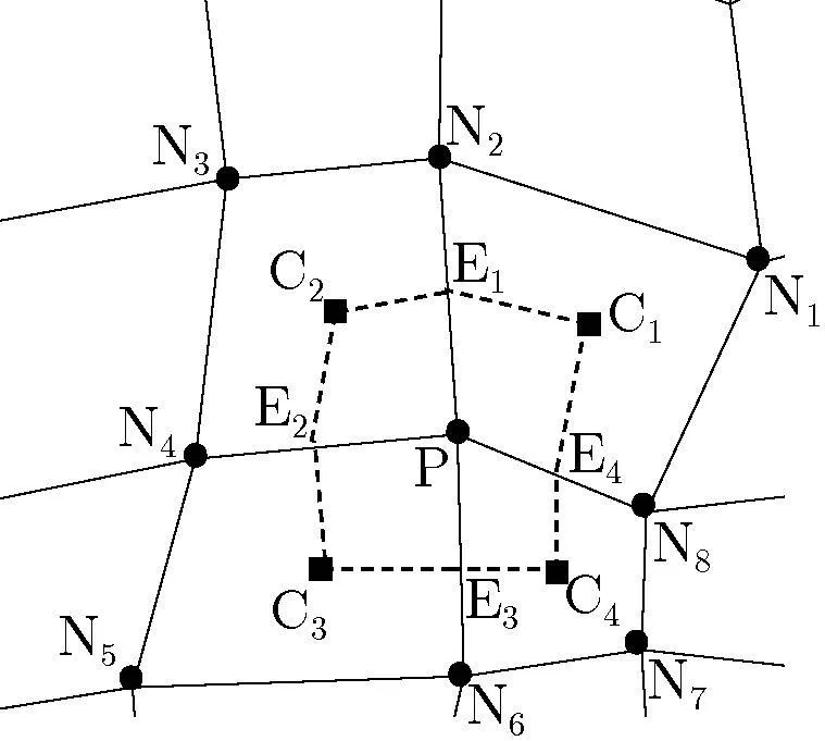
Figure 1:Control volume of node P in cell-vertex FV approach.
To perform spatial discretization,Eq.(6)is integrated over the control surface of the node P to get:

Using Green’s theorem,the surface integral of the stress term on the right-hand side of Eq.(12)can be simplified to a line integral of the form:

where,nedgeis the number of edges surrounding the control surface of the node P,∆lECis the length of the edges andˆnis the unit normal vector to it.
From Fig.1,the length of each edge,∆lEC,of the control surface is approximately quarter of the sum of the lengths of opponent edges of the quadrilateral grid,i.e.∆lE1C1=(∆lN1N2+∆lN8P)/4,thus:

Now,by substituting Eq.(14)into Eq.(12)and rearranging it,one can obtain:

whereAis the area of control surface of each node and
In the CV algorithm,the value ofDε is calculated at the center of the quadrilateral cells connected to the node P.Therefore,this value is constant over the surface of each cell.On the boundary nodes where the traction vector is prescribed,the stress tensor is calculated from Eq.(10)instead.Note that on the boundaries where the displacement is prescribed there is no need to solve the equation of motion.The computation of the strain rate tensor( ε)can be done by using Green’s circulation theorem for the calculation of the displacement differential terms in Eq.(7).For example:

Note that the position of the cell centers and mid-edge points do not appear in the CV approach formulation and there is no need to compute them.Thus,the cell vertex FV approach seems to be efficient because of less computer resources needed.
3.2 Cell-centered Finite volume approach
In this approach,which is developed here based on the CV FV approach presented in the previous section;Eq.(6)is discretized on each center point of the quadrilateral cells(the control surfaces),as shown in Fig.2.In this approach,like the CV FV approach,the stress term in Eq.(12),which is a surface integral,can be converted to a line integral by using Green’s circulation theorem:

where∆lNNis the length of each edge of the certain cell andˆnis the unit normal vector to it andnedgeis equal to the number of edges of quadrilateral cells,(herenedge=4).Note that there is no difference between the boundary and nonboundary cells in the standard form of CC FV approach.Integrating Eq.(6)over each control surface and substituting the stress term from Eq.(17),the discretized form of the governing equations can be obtained as follows:

which is similar to Eq.(15)for the CV FV approach.
The components of strain rate tensor( ε)on the non-boundary edges of each control surface,can be calculated by using Green’s circulation theorem for the computation of the displacement differential terms of Eq.(7).For example:

where the control surface C2N1C1N4around the edge N1N4 is shown in Fig.2.The computed values of displacement differential terms are used to calculate the strain rate tensor via Eq.(7)which if multiplied by the constitutive elasticity matrixresults in the stress tensor.For the boundary edges,where the traction vector is prescribed,the components of stress tensor can be computed from the boundary condition of Eq.(10).On the boundaries where the displacement vector is prescribed,boundary conditions are applied to the boundary vertices instead of the solution points.
As seen in Eq.(19),in addition to the displacement vector of the cell centers,which are the solution points,the displacement vector of the vertices should be calculated,
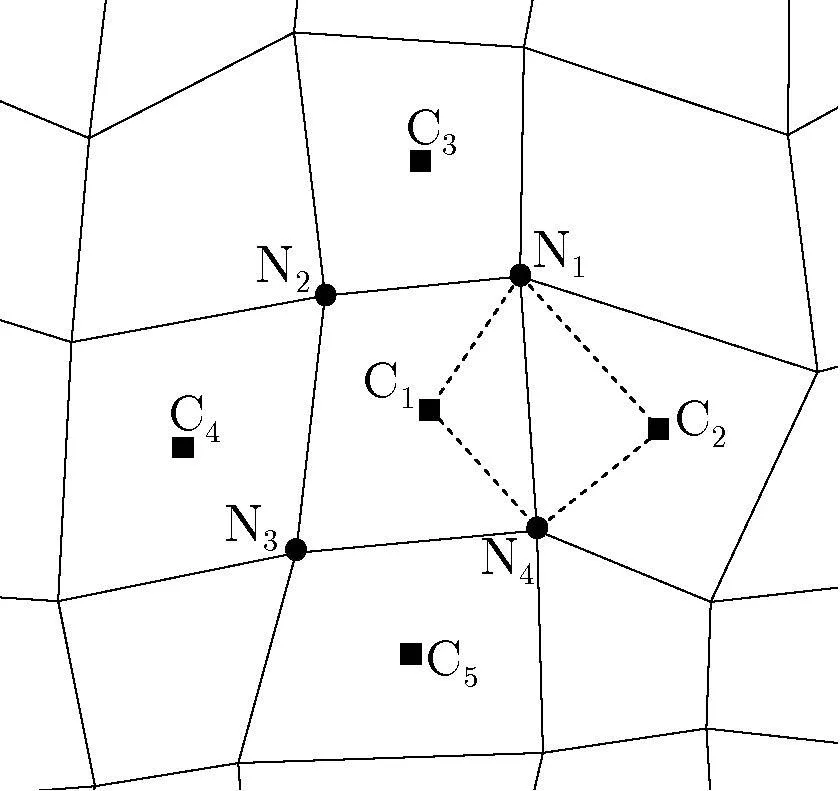
Figure 2:Control volume of cell C1in cell-centered FV approach.
which means that,the CC FV approach needs an additional memory overhead compared to the CV FV approach.The main problem with the CC FV approach is that,the vertices displacements should be calculated from the solution points by a suitable way.Linear interpolation usually exhibits unsatisfactory results,especially on distorted or irregular grids and thus,the functions used for the interpolation must be carefully selected.In addition,especial treatment is needed for the boundary nodes where their displacements must be calculated from the interior domain.
3.2.1Interpolation technique for cell-centered approach
Following Wheel(1996,1999),a multiple linear regression approach is applied for calculating the displacement of the vertices(nodes).In this approach,the displacement vector of each node is related to the displacement of neighboring cell centers by crossing a plane from them.If a specific cell is formed byNnodes,then,theudisplacements of the cell center is given by the following system of equations

and in the compact form:


which relates the displacement at the specific node to the displacement ofsurrounding cell centers.It is possible to express thevdisplacements in a similar manner.
3.2.2Boundary nodes treatment
There are two issues related to the boundaries in the CC FV approach.The first one is how to apply boundary condition to the boundary cells and the second is how to calculate the displacement of boundary nodes from the interior domain.If the displacements of boundary nodes are specified,the displacements are set on the fictitious cells adjacent to the boundary and the displacements of boundary nodes are set from this boundary condition,instead of the interior domain.Since the method applied here is iterative,thus,the values of the displacement of boundary nodes are updated at each iteration and the correct results are obtainable.If the traction vector is prescribed on the boundaries,then,the stress tensor of the adjacent edge is calculated from Eq.(10)and their computed values are considered directly inEq.(18).In the remaining of this part,the second issue,which is the extraction of boundary node displacement from the interior domain,will be discussed in details.Most of the boundary nodes join no more than two cells where it is impossible to generate coefficient vectorwith two points.Even,if a boundary connects more than two cells,it will be outside the region enclosed by them and therefore,the coefficients matrix become inaccurate.In this case,especial treatment is needed for the boundary nodes,not to affect the accuracy of the solution.Here,three methods are used for this purpose and will be discussed in details.
The first one is the extension of the multiple linear regression approach presented in the previous part.If it is impossible to generate coefficient vectorfor the boundary nodes,but it is possible to use the coefficient vector of the closest interior node,instead.Abbreviating this method with CC-R(which stands for Cell-Centered Regression approach),the results obtained show that this method is suitable in the test cases studied here.
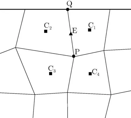
Figure 3:Extrapolation technique used for cell-centered FV approach.
As the second method,a simple extrapolation technique is employed.In this method,the displacement vector of a boundary node like Q in Fig.3,is computed from the pointsEandPwhere their displacements are interpolated from neighboring cells:

Abbreviating this method with CC-E(which stands for Cell-Centered Extrapolation approach)the results obtained show this approach is appropriate for nearly orthogonal grids and not suitable for irregular ones.The third method is inspired from the method presented by Wheel(1996,1999),but in an explicit way.In Wheel’s method,additional solution points are introduced in the midpoint of boundary edges,where the displacements of midpoints are obtained as a part of solution.Abbreviating this method with CC-BE(which stand for Cell-Centered Boundary Edge approach),the line cells in this method possess two characteristics; first,transmission of boundary conditions into the interior domain and second,calculation of the displacement of boundary vertices.The priority of this method compared to other works relies on the fact that,the displacements of boundary points are obtained as a part of solution while in other works they have to be evaluated subsequently.CC FV approach along with this method for boundary condition implementation obtains more accurate results compared to CV FV approach,as mentioned by Fallah(2004).Here,the solution method is explicit and the original method by Wheel is not applicable.But,it is possible to use Wheel’s method in the step where the displacements of boundary points are to be calculated from the interior domain.
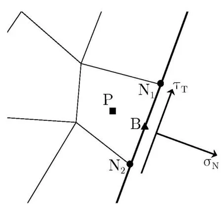
Figure 4:A typical line boundary cell.
In Fig.4 a typical line cell,B,lying next to the internal cell P,is illustrated.If stress boundary conditions are applied,which mean that the values of external stresses σNand τTare specified,then the following relationships exist between the internal stress components,σxxB,σxyBand,σyyBand the external stresses:

and

The internal stresses are related to the displacement of nodes N1 and N2 and also,the displacement of cells B and P via the constitutive relationship.Replacing the displacements in the above equations and rearranging them,the displacement of the point B is obtained.Note that,the procedure is similar to extrapolation techniques;each time step after the computation of the displacements of the interior domain by solving Cauchy’s equation of motion,the computed displacements are transferred to the boundary nodes by solving Eqs.(25)and(26)for boundary edge cells.
Although the implementation of the CC-BE approach used here differs from the original work by Wheel,the results obtained show the priority of this method over the CC-R and CC-E approaches in terms of accuracy(see the numerical results section.)
4 Time integration
In this research,an implicit backward differencing method of second-order accuracy is applied for the temporal discretization of the time-dependent term in Eqs.(15)and(18)which yields

Adding a pseudo time derivative term to Eq.(27),it is possible to convert the implicit time integration to explicit one which is matrix-free and computationally more efficient:

The above equation can be integrated in the pseudo-time τ using any standard timestepping methods like the fourth-order Runge-Kutta scheme.Also,the acceleration techniques like local time-stepping or residual smoothing can be applied for speeding up the convergence rate.When the computation reaches to steady-state solution in the pseudo-time,it means that the right hand-side of Eq.(28)approaches to zero and therefore,the solution in the physical time leveln+1 is obtained.Integrating from the velocity vector in the physical time,the displacement vector can be calculated as follow:

thus

4.1 Calculation of local and global time step sizes
An estimation of time step size can be obtained by using the wave propagation velocity,c,as follow:


For time accurate calculations,the real global time step size,∆tis equal to the minimum local time step size,∆τ,of all the control surfaces:

thus,it is different from fluid mechanics where the global time step size is independent of the local time steps.
5 Results and discussion
A number of benchmark problems concerned with the deformation of structures under external forces are selected to validate and assess the FV formulations presented in the previous sections,including CV(cell vertex),CC-BE(cell-centered boundary edge),CC-R(cell-centered regression)and CC-E(cell-centered extrapolation)approaches.The study has indicated for the problems considered here the inclusion of the nonlinear terms has negligible effects on the results and they can be ignored from the formulation.The results of different approaches are compared with the analytical solutions in terms of accuracy.In addition,the efficiency of different approaches in using computer resources is compared.
5.1 Deformation of a square plate under pure shear stress
The first problem that is a patch test case,is a 2D square plate whose sides have length 20 meters and is subjected to a pure external shear stress,τExt=1MPa.This test case is interesting in that it does not apply the boundary condition of Eq.(9).Note that,it only deals with the shear stress,σxy,and the generation of the normal stresses,σxxand σyyis a sign of errors in the solution.Another interesting feature of this test case is that the problem is symmetry which results in the symmetry of the solution.Any asymmetry in the solution is also a sign of error.The square plate and its external shear stress are illustrated in Fig.5.In this figure,the points"O","A"and"B"are marked which are used for the calculation of the numerical shear strain,γ.Young’s modulus of elasticity,E,Poisson’s ratio,ν,and the density,ρ,of the plate are 10 MPa,0 and 2,600 kg/m3,respectively.To perform a grid independent study,different grid sizes are applied for the simulation of test case 1,which are shown in Fig.6.A perturbed grid is also used to examine the effects of irregularity and skewness of the grid on the results of the CV and CC FV approaches.
Obviously,as the shape of square plate changes to rhombus,the right angle between edges"OA"and"OB"decreases the shear strain,γ.In Tab.1,the computed values of γ are presented.For the structural parameters stated before,the analytical solution of the shear strain,γ,is 0.1 and the maximum percentage error for different approaches with respect to the analytical solution is about 0.3%which shows the accuracy of the approaches in calculating the shear strain.Since the displacement field for this test case is a linear function of coordinates and that all the approaches used converge nearly with second-order accuracy,they are not sensitive to the grid size.Note that both the CV and CC approaches are sensitive to the grid irregularity and it causes a decrease in the accuracy of the solution(see Tab.1).
In Fig.7,the resultant rhombus obtained by the CV approach is depicted for grid numbers 2 and 4.It is shown that the results of the CV approach are not sensitive to grid irregularity.A same trend has been observed for the CC-BE and CC-R approaches,not given here for the sake of brevity.The results of the CC-E approach are presented in Fig.8,where the resultant position of the rhombus for grid number 4 is inaccurate and it has slightly rotated,while the symmetry of the problem indicates the symmetry of the solution.The study shows that the extrapolation technique applied is not suitable on irregular grids(see also Tab.1).

Figure 5:Schematic of test case 1.

Table 1:Comparison of the shear strain,γ,for different approaches.
The convergence history of the solution of this test case on uniform grids is depicted in Fig.9 which shows that the CV and CC approaches have nearly the same performance on regular grids.As the grid size is refined,the convergence rate of the solution is decreased.In Fig.10,the convergence history of the solution for the perturbed grid(grid number 4)is presented.This grid type has the same number of grid points as the unperturbed one(grid number 2).Comparing Figs.9 and 10,it is indicated that the convergence rate of the solution of the perturbed grid is slightly slower than that of the unperturbed one and it can be elongated abnormally for the CC-E approach.

Figure 6:Grids used for the study of test case 1;(1)6×6 elements;(2)20×20 elements;(3)40×40 elements;(4)perturbed 20×20 elements.
In Tab.2,a comparison between the CPU time and memory usage of different approaches on different grids is made which shows the efficiency of the CV approach in using computer resources compared with the CC approaches on both regular and irregular grids.The CC FV approach using different treatments of calculation of boundary nodes’displacement has nearly the same performance on regular grids.On irregular grids,the CC-BE and CC-R approaches have better performance than the CC-E approach.
5.2 Deformation of a fixed-free cantilever supporting an external load at free end
One of the benchmark problems in structural mechanics is a fixed-free cantilever which supports an external load at the free end[Augarde and Deeks(2008);Lv et al.(2007);Slone et al.(2003);Slone et al.(2004);G.H.Xia et al.(2007)].
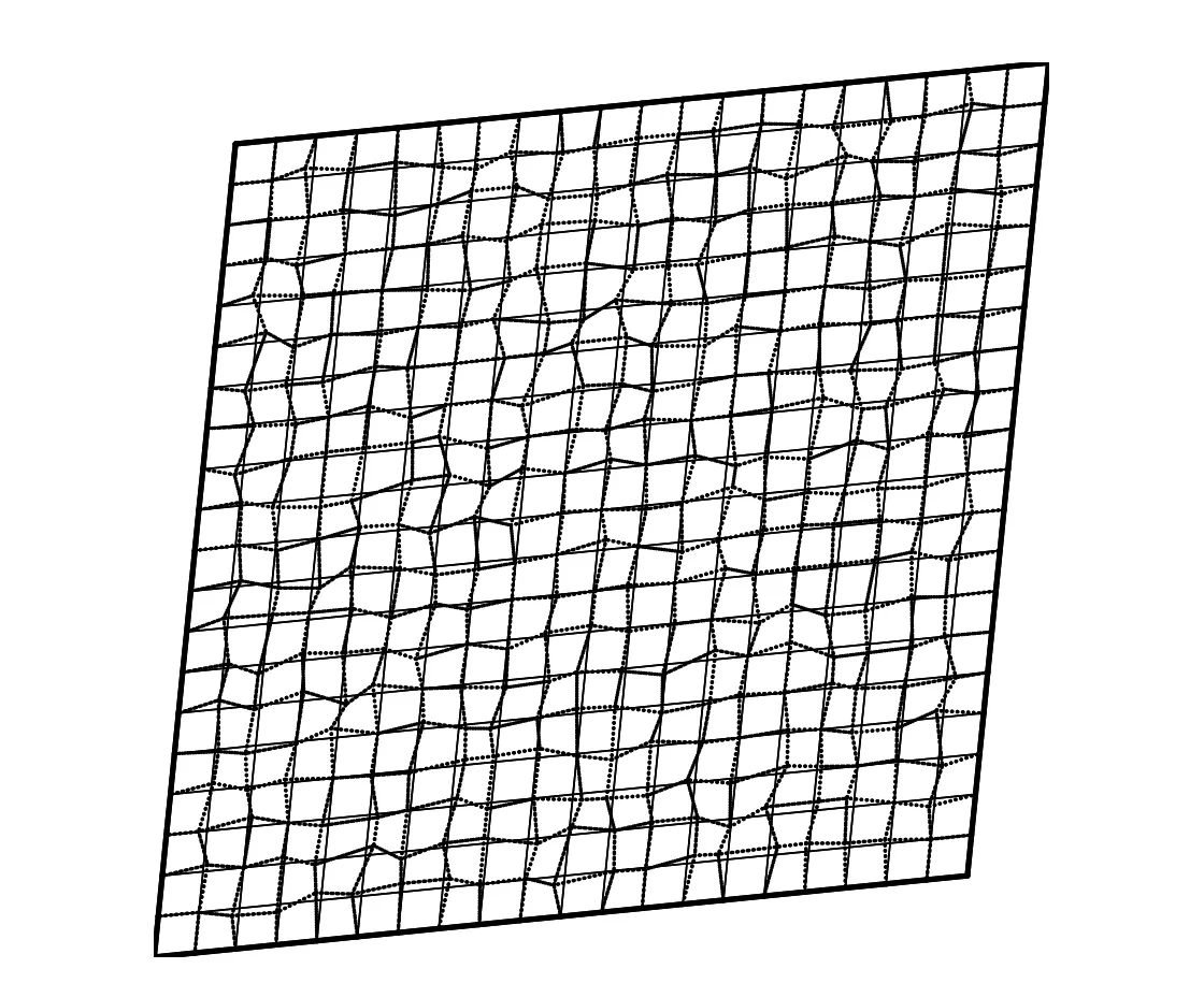
Figure 7:Grid numbers 2(solid line)and 4(dotted line)after deformation obtained by the CV approach.
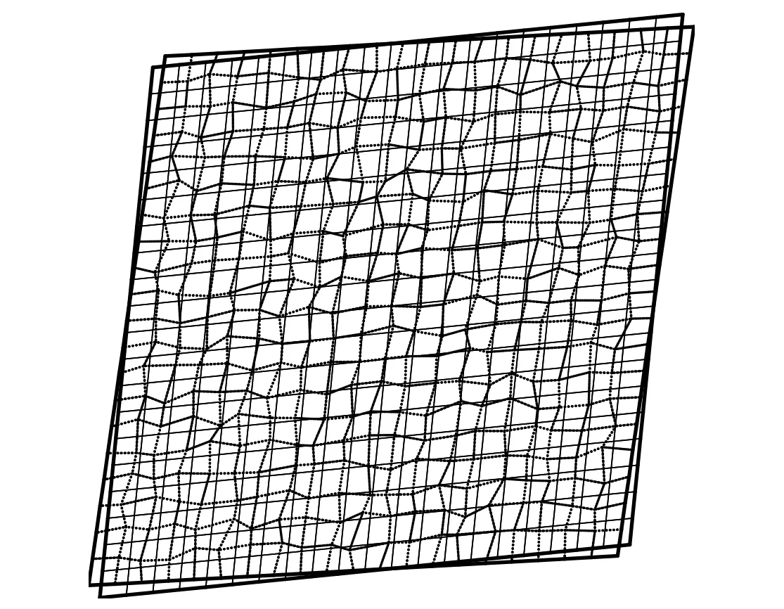
Figure 8:Grid numbers 2(solid line)and 4(dashed line)after deformation obtained by the CC-E approach.
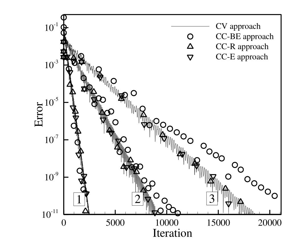
Figure 9:Comparison of convergence history of test case 1 for different approaches on grid numbers 1,2 and 3.
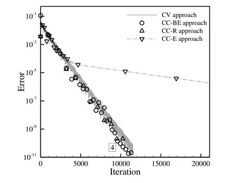
Figure 10:Comparison of convergence history of test case 1 for different approaches on grid number 4.
This test case problem involves a rectangular plate withL=20m andb=2m,as depicted in Fig.11,with the physical properties similar to that of the squareplate of the previous test case problem.Timoshenko and Goodier[Timoshenko and Goodier(1982)]proved that the stress field in the cantilever is as follows:

Table 2:Comparison of CPU time and memory usage of test case 1 for different approaches on different grids.

and,the displacement vector is given by:

In Ref.[Augarde and Deeks(2008)]it is stated that to obtain the stress and displacement fields of Timoshenko’s solution throughout the cantilever,the boundary conditions of the cantilever must be of the form depicted in Fig.11.It means that the external forcePmust be distributed according to the same parabolic law as the shearing stress σxyof Eq.(34)and at the clamped-end the displacement vector must follows Eq.(35).Selection of the boundary conditions in this way enables to perform a perfect comparison of the accuracy of different approaches with the analytical solution.Here,the value of 100 Pascal is selected for the external loadP.A set of numerical grids,ranging from coarse grids to fine grids and including non-uniform and perturbed grids are considered here to perform a grid independent study and to examine the effect of grid irregularity on the results of the CV and CC approaches.The following six grids(which are shown in Fig.12)are used for this study:
•Grid Number(1);20×2 boundary edges,63 nodes and 40 uniform square cells
•Grid Number(2);40×4 boundary edges,205 nodes and 160 uniform square cells
•Grid Number(3);80×8 boundary edges,729 nodes and 640 uniform square cells
•Grid Number(4);160×16 boundary edges,2737 nodes and 2560 uniform square cells
•Grid Number(5);100×10 boundary edges,734 nodes and 623 non-uniform quadrilateral cells
•Grid Number(6);80×8 boundary edges,729 nodes and 640 non-uniform cells(this mesh is obtained by perturbing the nodes of grid number 2)

Figure 11:Schematic of test case 2:a fixed-free cantilever supporting an external shear force.
In Fig.13,theL1-norm error of the displacement field w.r.t the analytical solution for the CV and CC approaches is compared for the uniform square grids.Obviously,the CV and CC–BE approaches obtain more accurate results than the other two approaches for all the grid sizes,where theirL1-norm errors are less than 0.0005 for both the approaches.Contrary,the CC-R and CC-E approaches are more sensitive to the grid size and they provide acceptable results only on finer grids.Figure 14 exhibits theL1-norms of the σxxcomponent of the stress tensor w.r.t the analytical solution,where the accuracy of different approaches are nearly second order.
In Tab.3,theL1-norm error of the displacement field and the σxxcomponent of the stress tensor are presented for all the grid sizes.It is notable that,as the grid size is re fined,the accuracy of the approaches is increased.The order of accuracy of the CV and CC-BE approaches is almost similar,while the CC-Rand CC-E approaches are less accurate.The study indicates that all the approaches are sensitive to the grid irregularity,however,the CV and CC-BE approaches show better performance than the other two approaches.It is demonstrated that the CV approach is less sensitive to grid irregularity and it may be due to more uniformity of the control volumes in this approach which are the median dual of the original mesh compared with the control volumes considered in the CC approaches which are the primal quadrilateral grids themselves.The results of the CC-R and CC-E approaches on regular grids are exactly the same whilst on irregular grids,the CC-R approach is more accurate.Similar to the previous test case,the CC–E approach fails to obtain accurate results on irregular grids,and it has a drastically large error.The results of this approach on grid number 6(the perturbed grid)are even worse than the results of grid number 2 which has a coarser grid.

Figure 12:Grids used for the study of test cases 2.

Table 3:Comparison of L1-norm error of displacement field and σxxw.r.t the analytical solution.
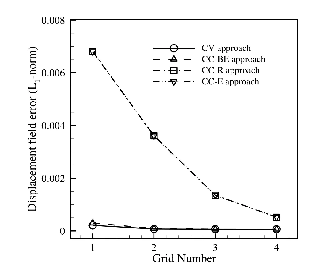
Figure 13:Comparison of L1-norm error of displacement field w.r.t the analytical solution for different approaches on uniform grids.
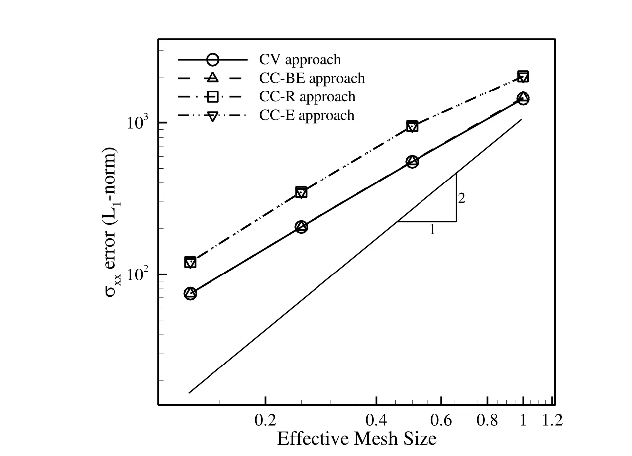
Figure 14:Comparison of L1-norm error of σxxw.r.t the analytical solution for different approaches on uniform grids.
In Fig.15,the contours of σxxfor grid number 3 are compared with the analytical solution for the steady condition which shows that the results of different approaches are almost identical.However,for grid number 6 it is different and as shown in Fig.16,the results are lumpy and for the CC-E approach it is unacceptable.
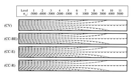
Figure 15:Comparison of contours of σxx(dashed lines)with the analytical solution(solid line)for different approaches on grid number 3.
The convergence rate of this test case to obtain the steady condition is depicted in Figs.17 and 18 for grid numbers 3 and 6,respectively.As it is obvious,the convergence rates of different approaches are nearly similar for both the grid types,except for the CC-E approach on the perturbed grid in which it has slower convergence rate.Note that the CC-E approach converges to an incorrect position for the beam although the time to reach a steady state solution is smaller in this approach.Similar to the previous test case,the convergence rate of the CC-BE approach is slower than the other approaches,which causes an increase in the CPU time.In Tab.4,the computer resources needed for the different approaches are compared in terms of the CPU time and memory usage.It is observed that the CV approach is the most efficient approach,because it does not apply the displacement of cell cen-ters in its solution procedure while the CC approaches apply the displacement of vertices along with the cell centers displacement.Although the CC–BE approach provides reasonable results comparable with the CV approach,it needs more computer resources among the finite volume approaches studied.Now,the fixed-free cantilever is subjected to a periodic end shear stress which causes a periodic motion in cantilever.The free end shear is equal to 100sin(Ωt)which is distributed uniformly at the free end and two different values of Ω=0.05 and Ω=0.1 radians per seconds are selected for this study.In Fig.19,the displacement history of the free-end of the beam in the y-direction,obtained on grid number 3,is compared with the analytical solution for the different approaches.This comparison is made for grid number 6 in Fig.20.As it is obvious,all the approaches are accurate enough on both the grid types,except for the CC-E approach on grid number 6 which is not accurate.The contours of σxx,obtained on the most re fined grid(grid number 4)for different positions of the beam obtained by the CV approach for Ω=0.05 are presented in Fig.21.In Fig.22,the contours of σxxobtained on grid number 3(dashed lines)and grid number 6(solid lines)for Ω=0.05 at the most lower position of the beam are compared for the different approaches.It is seen that the CC-E approach does not provide accurate results on irregular grids and the other CC approaches produce the results that are comparable with the CV approach.
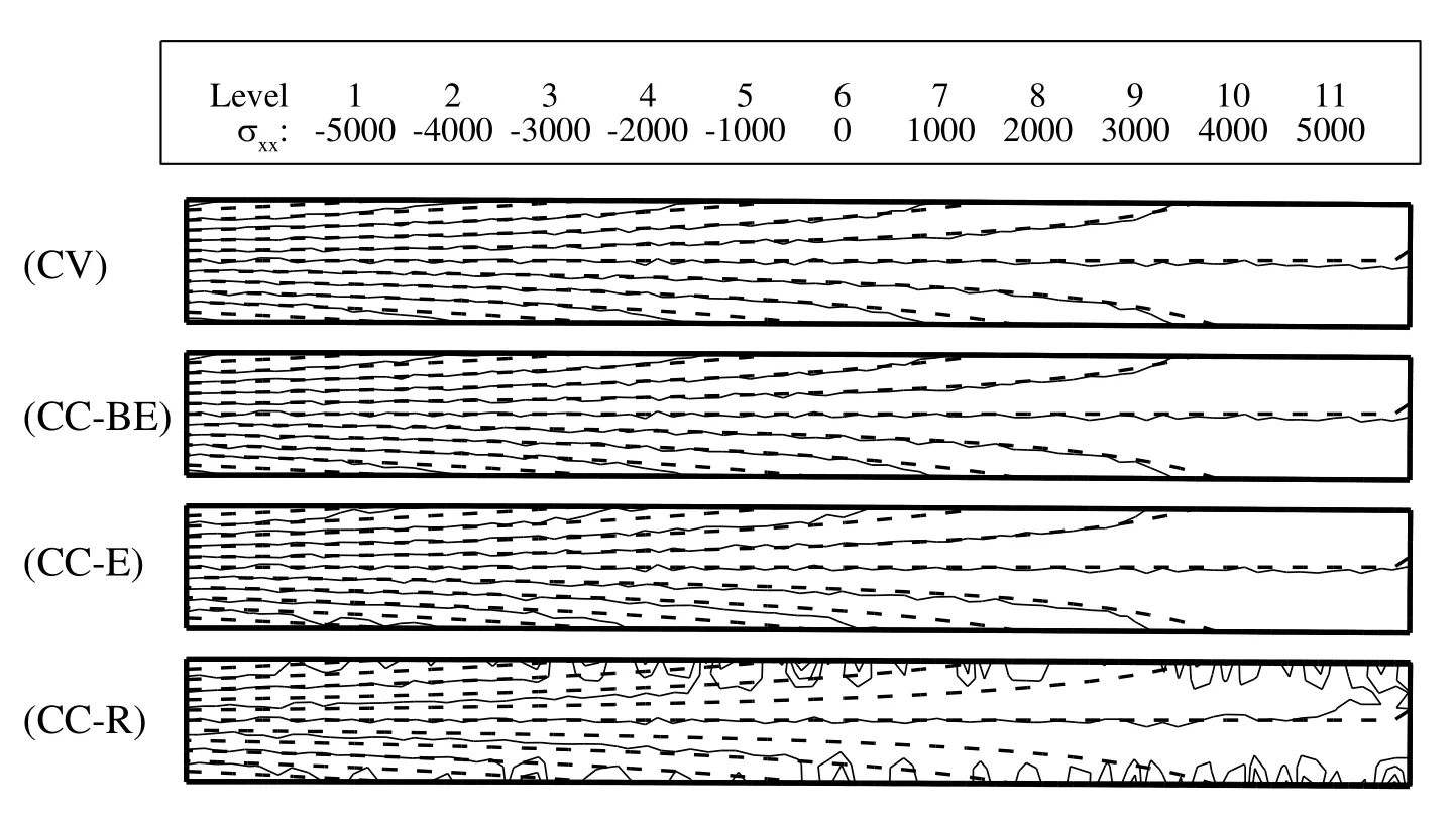
Figure 16:Comparison of contours of σxxfor different approaches on grid number 3(dashed line)and grid number 6(solid line).

Figure 17:Comparison of convergence history of test case 2 for different approaches on grid number 3.

Figure 18:Comparison of convergence history of test case 2 for different approaches on grid number 6.
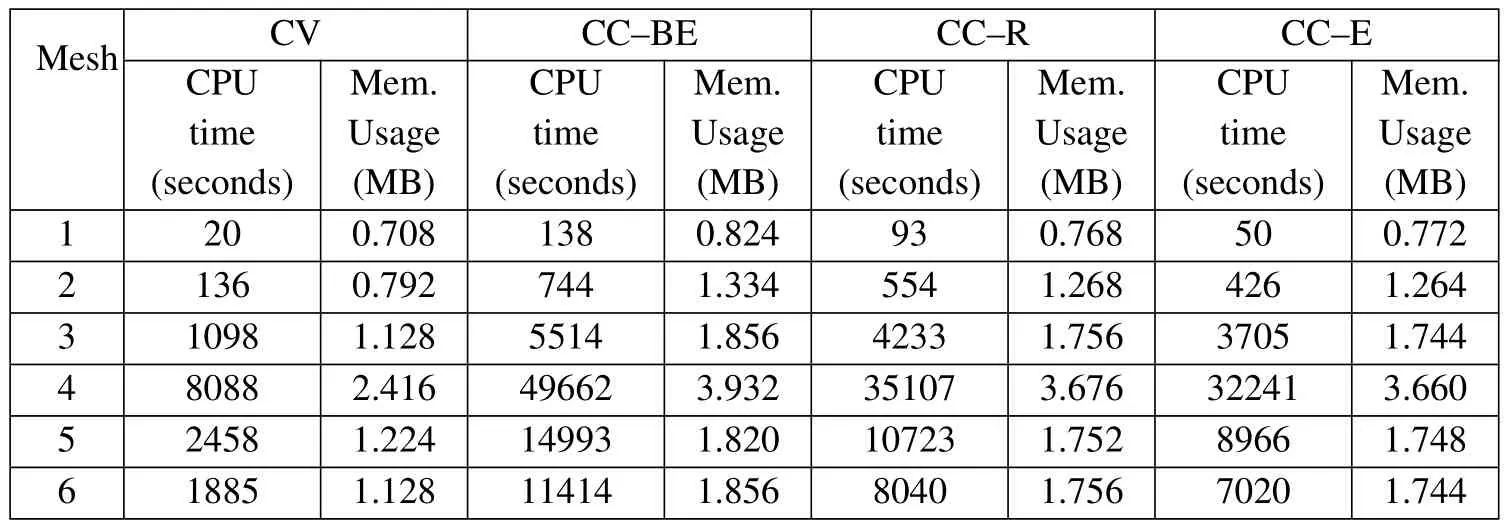
Table 4:Comparison of CPU time and memory usage of different approaches for test case 2.
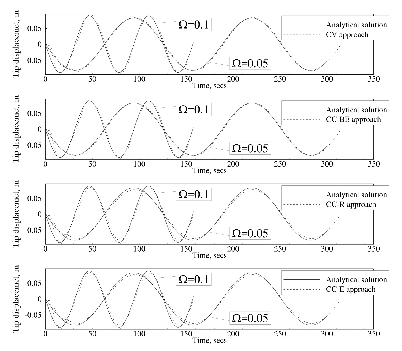
Figure 19:Comparison of the displacement history of the free-end of the clampedbeam under periodic load obtained on grid number 3 for different approaches with Ω=0.1 and 0.05.

Figure 20:Comparison of the displacement history of the free-end of the clampedbeam under periodic load obtained on grid number 6 for different approaches with Ω=0.1 and 0.05.
The pseudo-time convergence histories of the CV and CC approaches,obtained on grid numbers 3 and 6,are compared in Figs.23 and 24,respectively.Here,all the simulations on different grid types for different approaches are executed with an equal time step.The results indicate that among different approaches the CV FV approach has a more uniform behavior for the different grid types studied.Also,the CC-BE approach needs more iterations to converge in each physical time step which increases its CPU time requirement compared to the other approaches.

Figure 21:Contours of σxxat different positions of the clamped-beam under periodic load for the CV approach with Ω=0.05 on grid number 4.
5.3 Deformation of an in finite plate with a circular hole under axial stress
As the third test case,an in finite plate with a circular hole under uniform tension in one direction,as depicted in Fig.25,is analyzed.The normal stress σ0=10kPa is uniformly distributed along two edges of the plate with the physical properties ofE=10MPa,ν =0.3,and ρ =7,854kg/m3.If the radius of the hole is sufficiently small compared to the plate dimensions(forb>4a,the error in σxx,maxis less than 6%[Demirdži´c and Muzaferija(1994)],then the following analytical solution exists for the components of stress field[Timoshenko and Goodier(1982)]:
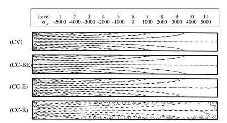
Figure 22:Comparison of contours of σxxfor the clamped-beam obtained on grid number 3(dashed lines)and grid number 6(solid lines)for different approaches with Ω=0.05 at the most lower position of the beam.
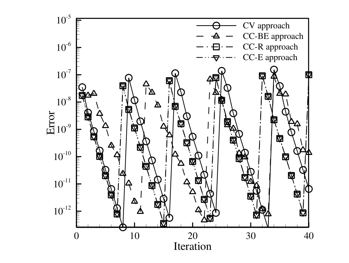
Figure 23:Comparison of convergence history of clamped-beam under periodic load for different approaches on grid number 3.

Figure 24:Comparison of convergence history of clamped-beam under periodic load for different approaches on grid number 6.

whererand θ are shown in Fig.25.Also,the displacement field is:

where µ =E/2(1+ν)and κ =3−4ν.Eliminating the influence of the finite plate dimensions,the analytical tractions calculated from Eq.(36)are imposed at the boundaries BC and CD.Also,zero tractions are applied at the hole boundary AE,while the solution is symmetric with respect to AB and ED lines.
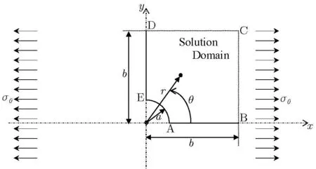
Figure 25:Schematic of test case 3:an in finite plate with a circular hole under axial stress.
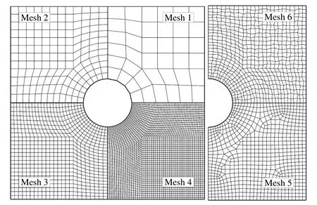
Figure 26:Grids used for the study of test cases 3;(1)uniform 160 elements;(2)uniform 640 elements;(3)uniform 2560 elements;(4)uniform 10240 elements;(5)non-uniform 2736 elements;(5)perturbed 2560 elements.
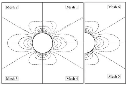
Figure 27:Comparison of contours of σxxobtained by the CV approach(dashed line)with the analytical solution(solid line)on different grids.
The grids used for the study of this test case are presented in Fig.26.A griddependent test is performed on four systematically re fined grids(grid numbers 1 through 4),and two irregular grids are applied(grid numbers 5 through 6)to study the effect of the grid irregularity on the accuracy and performance of the solution obtained by applying different approaches.In Fig.27,the contours of σxxare shown for the CV approach on the different grids.It can be seen that grid numbers 3 through 6 are able to accurately follow the analytical solution while,the results of grid numbers 1 and 2 are deviated from the analytical solution.In Fig.28,the variation of σxyalong the circular cross-sectionr=1.25a,obtained by the CV approach,is compared for grid numbers 1 through 4,which shows that grid numbers 1 and 2 are not suitable to obtain accurate results.In this figure,the results of the finest grid(which has 24 points along the hole perimeter)is coincident with the analytical solution.This comparison is made for grid numbers 3,5 and 6 in Fig.29 which shows the acceptable accuracy of the CV approach on the irregular(non-uniform and perturbed)grids.
In Fig.30,theL1-norm error of displacement field w.r.t the analytical solution is compared for grid numbers 1 through 4.It is observed that the CV approach is less sensitive to the grid size,although,all the approaches achieve to acceptable accuracies on finer grids.Figure 31 exhibits theL1-norm error of the σxxcomponent of the stress tensor w.r.t the analytical solution where the different approaches nearly converge with the second order accuracy.It is found that the CV approach gives the most accurate results among the approaches applied.The study shows that the performance of the CC-BE approach is better than two other CC approaches and it provides the results comparable with the CV approach especially on finer grids.It is also clear that the CC-R and CC-E approaches have nearly the same performance.

Figure 28:Grid-dependent test using uniform grids for σxyobtained by the CV approach along the circular cross-section r=1.25a.

Figure 29:Effect of grid irregularity on σxyobtained by the CV approach along the circular cross-section r=1.25a.

Figure 30:Comparison of L1-norm error of the displacement of point A(see Figure 25)using different approaches on different grids w.r.t the analytical solution.
In Tab.5,theL1-norm error of the displacement field and the σxxcomponent of the stress tensor are presented for all meshes.Similar to the previous test case,as the grid size is decreased,the accuracy of all the approaches is increased.The accuracy of the CV and CC-BE approaches is nearly similar for the non-uniform and perturbed grids,while the CC-R and CC-E approaches are less accurate.Similar to the previous test case,the CV approach is less sensitive to grid irregularity among the approaches studied.

Table 5:Comparison of L1-norm error of the displacement field and σxxw.r.t the analytical solution for different approaches.
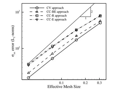
Figure 31:Comparison of L1-norm error of σxxw.r.t the analytical solution for different approaches on different grids.
The variation of the σxycomponent of the stress tensor for the different approaches along the circular cross-sectionr=1.25ais compared in Fig.32 for grid numbers 3 through 6.As it is obvious,the most accurate result is obtained by the CV approach,while the CC-BE approach stands on the second rank.It seems that increasing the grid skewness affects the results of FVM,while the CC approaches are more sensitive than the CV approach.Among the CC approaches,the CC-BE approach is less sensitive to the grid distribution and it obtains similar results compared to the CV approach.It can also be seen that,the CC-R and CC-E approaches coincide on grid number 5 while,on grid number 6 their results are different,which supports the results obtained for the previous test cases.
The accuracy of different approaches is assessed by comparing the calculated σxxcomponent of the stress tensor with the analytical solution in Fig.33.This comparison,which is made on grid numbers 3 and 6,indicates that the CV and CC-BE approaches properly follow the analytical solution for the entire region while the results of the CC-R and CC-E approaches have acceptable accuracy far from the hole boundary.
The convergence history of test case 3 on uniform grids is depicted in Fig.34 which shows a similar trend of the CV and CC approaches for the convergence of the solution.Similar to the previous test cases,the time step of the finest grid is the smallest,and thus its convergence rate is also the smallest.In Fig.35,the convergence history of the non-uniform and perturbed grids is compared with the unperturbed grid.It is shown that the convergence rate of the solution for the perturbed grid is slower than that of the unperturbed and non-uniform grids.It is found that the quality of the grid has a significant effect on the performance of the solution algorithm.
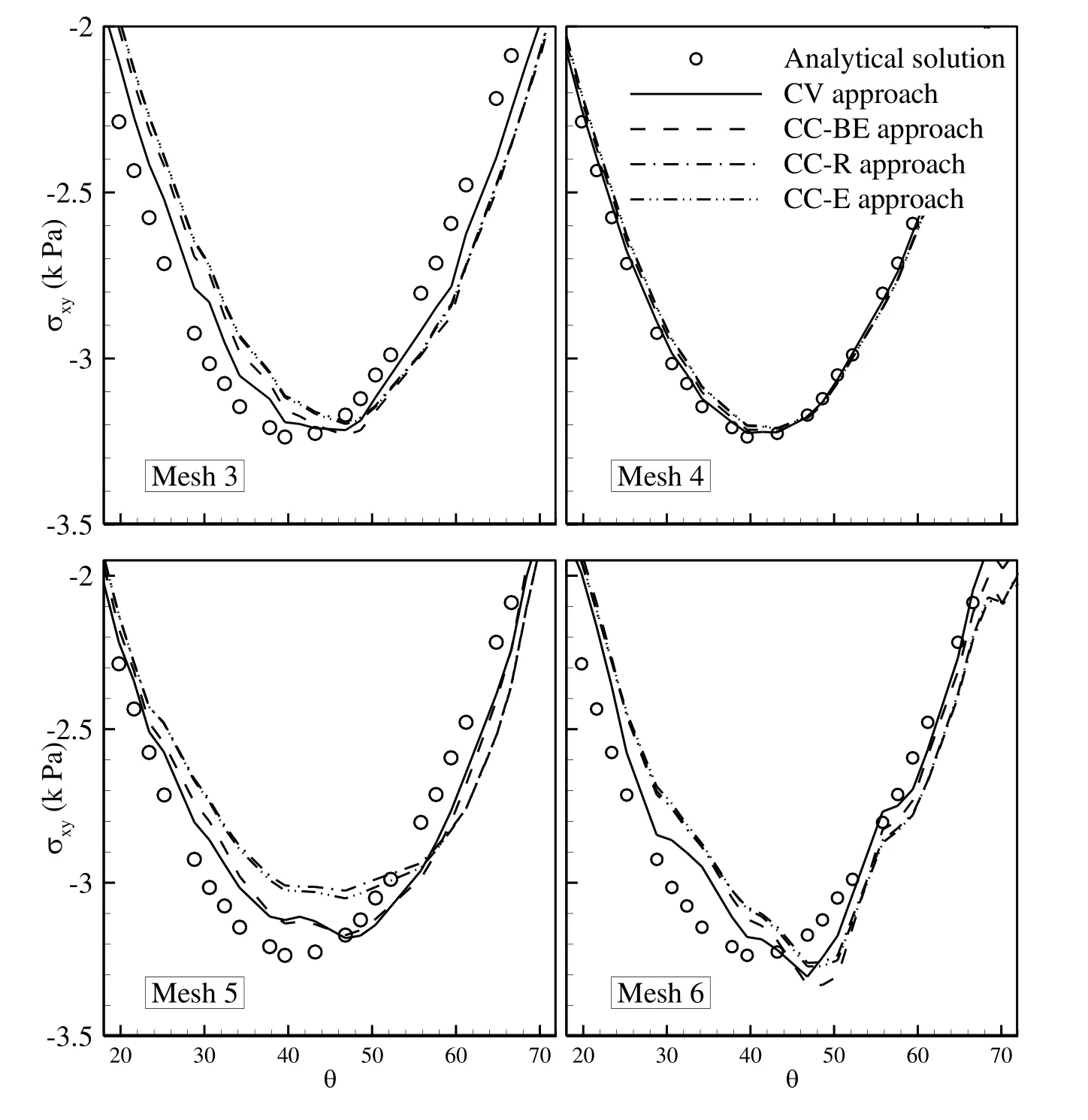
Figure 32:Comparison of σxyprofile along the circular cross-section r=1.25a obtained by the CV and CC approaches on different grids.
6 Conclusions
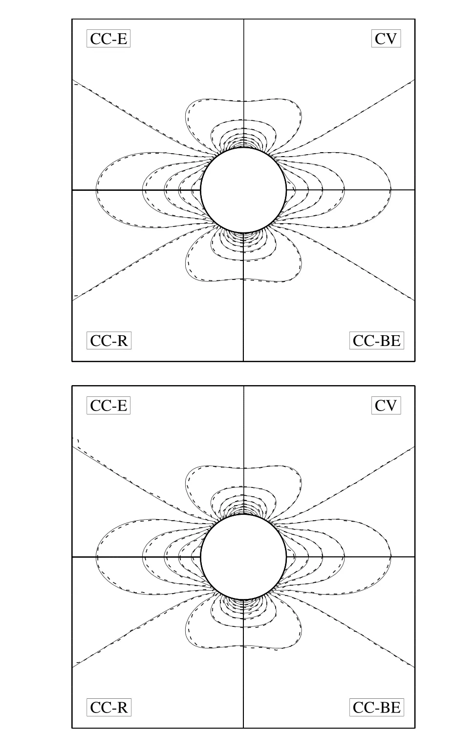
Figure 33:Comparison of contours of σxxobtained by the CV and CC approaches with the analytical solution(solid line)on grid number 3(upper)and grid number 6(lower).
In the present study,the cell-centered(CC)and cell-vertex(CV) finite volume(FV)approaches are employed and assessed for simulation of 2D structural dynamics on arbitrary quadrilateral grids.Three methods are used for the calculation of boundary nodes’displacement in the CC FV approach;an extrapolation technique(CC-E FV approach),a simple linear regression(CC-R FV approach)and the line boundary cell technique(CC-BE FV approach).To examine the effects of grid irregularity on the results of CC and CV FV approaches,different grid types are used ranging from regular square grids to irregular ones,including random perturbations of the grid nodes.A comparative study between the CV and CC FV approaches is made in terms of accuracy and performance of these approaches by simulating some benchmark test cases in structural dynamics on different grid types.Some conclusions and remarks regarding the present study are as follows:

Figure 34:Comparison of convergence history of test case 3 for different approaches on grid numbers 1 through 4.

Figure 35:Comparison of convergence history of test case 3 for different approaches on grid numbers 3,5 and 6.
1.The study shows that the results obtained by applying the CV and CC approaches for the problems considered herein are in good agreement with the analytical solutions and all the approaches converge nearly with the second order accuracy.It is observed that the CV approach is the most accurate approach among the approaches studied herein and it can provide reasonable results on different grid types.
2.It is indicated that all the approaches are capable to obtain accurate results on the regular fine grids.The study shows that on regular grids the accuracy and performance of the CC-BE approach is better than two other CC approaches and it can provide the results comparable with the CV approach.It is also shown that the CC-R and CC-E approaches have nearly the same accuracy and performance on regular grids.
3.It is observed that the CV approach is the most efficient approach in terms of the CPU time and the memory required compared to the CC approaches,because it does not apply the displacement of cell centers in its solution procedure while the CC approaches apply the displacement of vertices along with the cell centers displacement.The CC FV approach using different treatments of calculation of boundary nodes’displacement has nearly the same convergence rate.Although the CC–BE approach provides reasonable results comparable with the CV approach,it needs more computer resources among the finite volume approaches studied.
4.It is found that the quality of the grid has a great effect on the accuracy and performance of the solution obtained by applying both the CV FV and CC FV approaches.It is demonstrated that the CV approach is less sensitive to the grid irregularity and it may be due to more uniformity of the control volumes in this approach which are the median dual of the original mesh.Among the CC FV approaches,the CC BE approach is less sensitive to the grid irregularity and it obtains almost identical results compared to the CV approach.Although the CC-R and CC-E approaches give nearly the same results on regular grids,the CC-E approach may fail to obtain accurate results on irregular grids.
5.The present study demonstrates the suitability of using the CV FV and CC FV approaches for the simulation of 2D structural dynamics on arbitrary quadrilateral grids.Note that the CC FV approach requires particular care for the implementation and calculation of boundary nodes’displacement to achieve adequate results.The extension of the study performed herein to assess the CV FV and CC FV approaches for computing 2D structural dynamics on arbitrary triangular grids is straightforward to perform.
6.Since the CCFV is common method to use is fluid dynamics problems,based on the present study that indicates the CC FV method can also provide accurate and reliable results in structural dynamics problems,one can develop and apply a unified formulation based on the CC FV method for an accurate and efficient simulation of fluid-solid interaction problems.
Acknowledgement:The authors would like to thank Sharif University of Technology for the support of this research.
Atluri,S.;Han,Z.;Rajendran,A.(2004):A new implementation of the meshless finite volume method,through the MLPG “mixed”approach.CMES:Computer Modeling in Engineering&Sciences,vol.6,no.6,pp.491-514.
Atluri,S.N.(2005):Methods of computer modeling in engineering&the sciences volume I.Tech Science Press,560 pages.
Atluri,S.N.;Liu,H.T.;Han,Z.D.(2006):Meshless local Petrov-Galerkin(MLPG)mixed collocation method for elasticity problems.CMES:Computer Modeling in Engineering&Sciences,vol.14,no.3,pp.141-152.
Augarde,C.E.;Deeks,A.J.(2008):The use of Timoshenko’s exact solution for a cantilever beam in adaptive analysis.Finite elements in analysis and design,vol.44,no.9-10,pp.595-601.
Bailey,C.;Cross,M.(1995):A finite volume procedure to solve elastic solid mechanics problems in three dimensions on an unstructured mesh.International Journal for Numerical Methods in Engineering,vol.38,no.10,pp.1757-1776.
Boris,D.;James,T.;Eric,N.;Jeffery,W.;Hiroaki,N.(2009):Comparison of Node-Centered and Cell-Centered Unstructured Finite-Volume Discretizations Part I:Viscous Fluxes 47th AIAA Aerospace Sciences Meeting including The New Horizons Forum and Aerospace Exposition:American Institute of Aeronautics and Astronautics.
Delis,A.I.;Nikolos,I.K.;Kazolea,M.(2011):Performance and Comparison of Cell-Centered and Node-Centered Unstructured Finite Volume Discretizations for Shallow Water Free Surface Flows.Archives of Computational Methods in Engineering,vol.18,no.1,pp.57-118.
Demirdžic´,I.;Martinovic´,D.(1993):Finite volume method for thermo-elasto-plastic stress analysis.Computer Methods in Applied Mechanics and Engineering,vol.109,no.3-4,pp.331-349.
Demirdži´c,I.;Muzaferija,S.(1994):Finite volume method for stress analysis in complex domains.International Journal for Numerical Methods in Engineering,vol.37,no.21,pp.3751-3766.
Demirdži´c,I.;Muzaferija,S.(1995):Numerical method for coupled fluid flow,heat transfer and stress analysis using unstructured moving meshes with cells of arbitrary topology.Computer Methods in Applied Mechanics and Engineering,vol.125,no.1-4,pp.235-255.
Demirdži´c,I.;Muzaferija,S.;Peri´c,M.(1997):Benchmark solutions of some structural analysis problems using finite-volume method and multigrid acceleration.International Journal for Numerical Methods in Engineering,vol.40,no.10,pp.1893-1908.
Dong,L.;Alotaibi,A.;Mohiuddine,S.A.;Atluri,S.N.(2014):Computational methods in engineering:a variety of primal&mixed methods,with global&local interpolations,for well-posed or ill-posed BCs.CMES:Computer Modeling in Engineering&Sciences,vol.99,no.1,pp.1-85.
Fallah,N.(2004):A cell vertex and cell centred finite volume method for plate bending analysis.Computer Methods in Applied Mechanics and Engineering,vol.193,no.33-35,pp.3457-3470.
Fallah,N.(2006):On the use of shape functions in the cell centered finite volume formulation for plate bending analysis based on Mindlin–Reissner plate theory.Computers&structures,vol.84,no.26-27,pp.1664-1672.
Fryer,Y.D.;Bailey,C.;Cross,M.;Lai,C.H.(1991):A control volume procedure for solving the elastic stress-strain equations on an unstructured mesh.Applied Mathematical Modelling,vol.15,no.11-12,pp.639-645.
Giannopapa,C.G.(2004):Fluid structure interaction in flexible vessels.PhD Thesis,King’s College,London.
Greenshields,C.J.;Weller,H.G.;Ivankovic,A.(1999):A finite volume formulation for fluid structure interaction.Paper presented at the Second International Symposium on Finites Volumes for Complex Applications:Problems and Perspectives,Duisburg,Germany.
Han,Z.D.;Rajendran,A.M;Atluri,S.N.(2005):Meshless Local Petrov-Galerkin(MLPG)Approaches for Solving Nonlinear Problems with Large Deformation and Rotation.CMES:Computer Modeling in Engineering&Sciences,vol.10,no.1,pp.1-12.
Hattel,J.H.;Hansen,P.N.(1995):A control volume-based finite difference method for solving the equilibrium equations in terms of displacements.Applied Mathematical Modelling,vol.19,no.4,pp.210-243.
Henry,F.S.;Collins,M.W.(1993a):A novel predictive model with compliance for arterial flows.ASME-Publications-BED,vol.26,pp.131-135.
Henry,F.S.;Collins,M.W.(1993b):Prediction of transient wall movement of an incompressible elastic tube using a finite volume procedure.Paper presented at the Proceedings of the Second International Conference on Computers in Biomedicine,BIOMED 93,UK.
Jaluši´c,B.;Sori´c,J.;Jarak,T.(2014):Mixed Meshless Local Petrov Galerkin(MLPG)Collocation Method for Modeling of Heterogeneous Materials.In 11th World Congress on Computational Mechanics(WCCM XI).
Jasak,H.;Weller,H.G.(2000):Application of the finite volume method and unstructured meshes to linear elasticity.International Journal for Numerical Methods in Engineering,vol.48,no.2,pp.267-287.
Li,S.;Atluri,S.N.(2008):The MLPG Mixed Collocation Method for Material Orientation and Topology Optimization of Anisotropic Solids and Structures.CMES:Computer Modeling in Engineering&Sciences,vol.30,no.1,pp.37-56.
Lv,X.;Zhao,Y.;Huang,X.Y.;Xia,G.H.;Su,X.H.(2007):A matrix-free implicit unstructured multigrid finite volume method for simulating structural dynamics and fluid–structure interaction.Journal of Computational Physics,vol.225,no.1,pp.120-144.
Moosavi,M.;Khelil,A.(2008):Accuracy and computational efficiency of the finite volume method combined with the meshless local Petrov–Galerkin in comparison with the finite element method in elasto-static problem.ICCES,vol.5,no.4,pp.211-238.
Oñate,E.;Cervera,M.;Zienkiewicz,O.C.(1994):A finite volume format for structural mechanics.International Journal for Numerical Methods in Engineering,vol.37,no.2,pp.181-201.
Papadakis,G.;Giannopapa,C.G.(2006):Towards a unified solution method for fluid-structure interaction problems:progress and challenges.Paper presented at the 10th International Symposium on Emerging Technology in Fluids,Structures and Fluid-Structure Interactions,Vancouver,Canada.
Patanker,S.V.(1980):Numerical Heat Transfer and Fluid Flow.Washington,DC:Hemisphere.
Slone,A.K.;Bailey,C.;Cross,M.(2003):Dynamic solid mechanics using finite volume methods.Applied Mathematical Modelling,vol.27,no.2,pp.69-87.
Slone,A.K.;Pericleous,K.;Bailey,C.;Cross,M.;Bennett,C.(2004):A finite volume unstructured mesh approach to dynamic fluid–structure interaction:an assessment of the challenge of predicting the onset of flutter.Applied Mathematical Modelling,vol.28,no.2,pp.211-239.
Taylor,G.A.(1996):A vertex-based discretization scheme applied to material non-linearity within a multi-physics finite volume framework.PhD Thesis,The University of Greenwich,London,UK.
Taylor,G.A.;Bailey,C.;Cross,M.(2003):A vertex-based finite volume method applied to non-linear material problems in computational solid mechanics.International Journal for Numerical Methods in Engineering,vol.56,no.4,pp.507-529.
Timoshenko,S.P.;Goodier,J.N.(1982):Theory of Elasticity.New York:McGraw-Hill.
Wheel,M.A.(1996):A geometrically versatile finite volume formulation for plane elastostatic stress analysis.The Journal of Strain Analysis for Engineering Design,vol.31,no.2,pp.111-116.
Wheel,M.A.(1997):A finite volume method for analysing the bending deformation of thick and thin plates.Computer Methods in Applied Mechanics and Engineering,vol.147,no.1-2,pp.199-208.
Wheel,M.A.(1999):A mixed finite volume formulation for determining the small strain deformation of incompressible materials.International Journal for Numerical Methods in Engineering,vol.44,no.12,pp.1843-1861.
Xia,G.;Lin,C.-L.(2008):An unstructured finite volume approach for structural dynamics in response to fluid motions.Computers&structures,vol.86,no.7-8,pp.684-701.
Xia,G.H.;Zhao,Y.;Yeo,J.H.;Lv,X.(2007):A 3D implicit unstructured-grid finite volume method for structural dynamics.Computational Mechanics,vol.40,no.2,pp.299-312.
Zienkiewicz,O.C.;Taylor,R.L.(1989):The Finite Element Method:Basic Formulation and Linear Problems(Vol.1).Maidenhead,UK:McGraw-Hill.
Zhang,T.;Dong,L.;Alotaibi,A.;Atluri,S.N.(2013):Application of the MLPG Mixed Collocation Method for Solving Inverse Problems of Linear Isotropic/Anisotropic Elasticity with Simply/Multiply-Connected Domains.CMES:Computer Modeling in Engineering&Sciences,vol.94,no.1,pp.1-28.
1Aerospace Engineering Department,Sharif University of Technology,Tehran,Iran.

