Numerical Investigation of a Hybrid Wave Absorption Method in 3D Numerical Wave Tank
Numerical Investigation of a Hybrid Wave Absorption Method in 3D Numerical Wave Tank
Chengxi Li1
Applying an ef ficient numerical wave absorption method is very important for realization of an open sea condition especially for long time numerical fluid structure interaction simulation.This paper proposed a hybrid numerical wave absorption method for the fully nonlinear fluid structure simulation.A numerical code“QBEM”which is based on the quadratic boundary element method is applied to evaluate the ef ficiency of the wave absorption methods and damping schemes by checking the energy conservation and wave elevation in the computational domain.Speci fically,we conduct a 3D numerical wave tank experiment to find the bestperforming damping scheme inside the damping zone and the associated optimal ramp shape.In addition,different damping coef ficients,phase velocities and numerical domain sizes are introduced and compared by the numerical wave tank in order to evaluate their in fluences on the numerical wave absorption.At last,the most accurate and ef ficient hybrid numerical wave absorption method is introduced and validated by the comparison between the numerical results and physical wave tank experiments.
Hybrid wave absorption method;numerical wave tank;quadratic boundary element method.
1 Introduction
The effective controlling of the outgoing and re flection waves from the physical or numerical boundary is very important for both experimental and numerical studies of fluid structure interaction problems.In a physical wave tank experiment,some speci fic designed means such as a sponge layered structure,multiple perforated thin plates or a sloped beach at the end are always installed to prevent the re flection waves from the end wall.For a reliable experiment,the re flection wave from the rigid end wall should be less than 10%.Mathematically,the fluid domain should extend to in finity in the horizontal direction and a radiation condition at in finity isoften required to make the problem well-posed.This condition states that the radiation waves or diffraction waves are outgoing waves only,and is known as Sommerfeld radiation condition[Sommerfeld(1949)].For direct numerical simulations,the computational domain needs to reduce to a minimum size so the fluid domain will be truncated at some distance by arti ficial boundaries.These boundaries are often referred as open boundaries.To prevent the re flection waves from these open boundaries,some kind of arti ficial boundary condition is required at this kind of boundary such as the periodic boundary condition,theoretical-numerical couple boundary condition,radiation condition method and wave absorbing beach methods.In the periodic boundary condition[Longuet-Higgins and Cokelet(1976)],the solution is assumed to be periodic in space so that the value of the unknowns on one side of the vertical boundary can be set to equal to those on the other vertical boundary of the computational domain.One example could be found in the study byLonguet-HigginsandCokelet(1976),theyappliedperiodicityfortheirboundary integral method to be able to transform the free surface into a circle.From previous studies,it is found that this technique is very easy to be implemented and open boundaries can be chosen at a very short distance.However,its application in fluid structure problem is often limited due to its requirement of periodicity.Another method to absorb the re flection wave is the simple far filed solution method.In this technique,a simpli fied outer solution which satis fies the far field radiation condition and may be obtained in an analytical form is used to match the inner numerical solution at the open boundary.An example of this technique is so called hybrid integral equation method where the diffraction of waves by an in finite cylinder is studied[Liu and Abbaspour(1983)].The problem is solved in the interior with a boundary integral equation method and use an analytical solution for the outer domain satisfying the linearized free surface conditions and the Sommerfeld’s radiation condition at in finity.Other examples are the linear outer solution matches the nonlinear 2D computations in the interior[Lin,Newman and Yue(1984)]and the deep water time harmonic radiation problem[Nestegard and Sclavounos(1984)].However,this method includes more dif ficult implementation and high computational overhead which is not suitable for our problem which involves complicated fluid structure interactions.On the other hand,several types of radiation conditions have also been proposed for the open boundary[Sommerfeld(1949);Orlanski(1976)].The condition most widely used is the Sommerfeld condition as shown in Eq.1.


2 Mathematical formulation
2.1 Nonlinear potential theory
In this section,we state the nonlinear potential fluid theory used in present study.Under the frame of potential theory,we assumed the fluid to be irrotational,inviscid and incompressible flow.As a result,the fluid velocity may be represented by the gradient of a velocity potential(i.e.u=∇φ).Further,we could describe the conservation of mathematically by the Laplace equation(Eq.2).

Then,thedynamicfreesurfaceboundarycondition(Eq.3)isdescribedbyBernoulli’s equation under the assumption that the pressure is constant across the free surface.

Furthermore,the kinematic free surface condition(Eq.4),de fining the position of the free surface is consistently with the fluid motion on the free surface.

At last,the zero flux condition at solid boundaries is imposed by:

Here η is the free surface wave elevation and U is the normal velocity of the solid boundary SBwith the direction pointing into the fluid domain.With Eq.2 to Eq.5,the governing field equations with fully nonlinear boundary conditions are described.Several methods could be implemented to solve the above governing equations such as the finite element method[Yan,Ma and Cheng(2012)],MLPG approach[Atluri and Zhu(1998);Atluri and Shen(2002)]or boundary element method.For the present study,the prediction tool‘QBEM’which is based on boundary element method is employed and the main characteristics of the code‘QBEM’are brie fly described in the next sections.
2.2 The mixed-Eulerian-Lagrangian(MEL)approach
In ‘QBEM’,MEL[Longuet-Higgins and Cokelet(1976)]approach has been employed.It mainly involves two main steps:
1.With the speci fied φ (x,t)on the free surface SFand φn(x,t)on the impervious boundary SB,the boundary value problem could be solved for φn(x,t)SFand φ(x,t)SBby solving the boundary integral equation.
2.Integrate the kinematic and dynamic free surface boundary condition(Eq.3 and Eq.4)for the new free surface position and new velocity potential.Repeat the iteration.
In this approach,the first step is realized by the quadratic boundary element method and solved using iterative methods.The fourth-order Runge-Kutta scheme is applied for time integration of the nonlinear free-surface boundary conditions in the second step in the time domain.The validity of this method has been well established in the study of breaking wave dynamics,fully-nonlinear wave diffraction and generation(Liu,Xue and Yue 2001),and large-amplitude motions of floating bodies in waves.As can be expected,the main computation effort and storage are dominated by step 1,so a brief description of the procedure for solving the boundary integral equation will be given in the following section.
2.3 Boundary integral equation
The derivation of the boundary integral equation(BIE)is given in this section by following the procedure in Newman(1977).To solve the Laplace’equation(Eq.2)in the volumeof the fluid domain within a closed surface S,we first denote the two solutions of the Eq.2 as φ and G.By applying the divergence theory,we could have:

Then we de fine a source point atin the coordinatex=(x,y,z)with unit strength,then the potential at the field pointxis given by:

It is known that Eq.7 is the solution of Laplace’s equation with respect toxandSubstitute Eq.7 into Eq.6,a singular point is occurred at r=0.In order to avoid this dif ficulty,a small sphere of radius r=ε with surface Sεis used to surround the source point.Then a closed surface surrounding the volume of the fluid is formed by S+Sεwhich is interior to S but exterior to Sε[Newman,(1977)].Within this volume,no singular is included and Eq.6 could be replaced by:


Thus,if(x,y,z)is inside S,

On the other hand,when the source point is situated on surface S,the surface of the small sphere would change to a hemisphere and Eq.10 would be changed to:

As a result,the boundary value problem could be reformulated as the boundary integral equation for the velocity potential of φ (x)in ∀:


Here IFd,IBd,IFSand IBSrepresent the elemental integrals.In ‘QBEM’,the quadratic boundary element method is used where the value of the variables(x,y,z,φ,φn)at any location of an element is de fined in terms of nine nodal values and Lagrangian interpolation function.The final form of the elemental integrals is expressed as:

Here J(s,t)is the Jacobian transformation function from curvilinear element to the parametric space.L is the interpolation function:

It should be noted that the above analysis is only valid for the potential fluid where Laplace’s equation is the governing equation in the fluid domain.For the case with other nonlinear governing equations,such as the nonlinear solid mechanics problem,the integral representations would involve not only boundary integrals but also domain integrals.In this case,special care is needed for the derivation and computation.A so called “ field-boundary-element-method”should be used[Zhang and Atluri(1986),(1987)].In such case,a higher order singular integral would be formed when the source point is inside the fluid domain or on the domain surface[Okada,RajiyahandAtluri(1988),(1989),(1994)].Certainmethodshavebeenimplemented to solve this dif ficulty.By establish new regularized boundary integral equation for the gradients of the original unknowns,an algorithm was developed and could solve the singularity problem by avoiding calculating the singular integrals[Okada,Rajiyah and Atluri(1988),(1989),(1990)].Then the final solution could be obtained by differentiating the solution of the new BIE with respect tox.
2.4 Equations of motion
In ‘QBEM’,the six degrees of freedom of the body motion are simulated.The formulation begins with the application of Newton’s law,a statement of dynamic equilibrium.The acceleration of the body is balanced by the external forces as:

Here M is the inertial matrix for the body,and C is the matrix of external restoring force from mooring lines.Fhrepresents the hydrodynamics force acting on the body and could be found by integrating the pressure given by the Bernoulli equation over the entire ship hull after solving the velocity potential at each time step.In addition,we adopt a simple model to include the nonlinear viscous damping force Fvin our potential flow based numerical scheme.The drag force term in Morison’s equation,which is related to water particle velocity,was used to represent the viscous force acting on the body.The form of the viscous force is:

Where ufis the fluid velocity,ubis the instantaneous body velocity,and Cdis the drag coef ficient whose value is selected to be 1.0 in our study.
3 3D numerical wave tank
The performance of the damping beach is assessed by a numerical wave tank is made in the ‘QBEM’.As shown in Fig.1,the boundary condition on the left inputs irregular waves to the computation domain in form of a numerical wave maker while the right boundary condition implies a rigid wall.The conservation of total wave energy and the wave elevation in the computational domain are checked during the time simulation.Similar method was also used by Kim,Koo and Hong(2104)in the optimization study of the original damping zone method and was found to be effective and valid.The total energy of the computational domain is expressed as E=EK+EP.Here Ekis the wave kinetic energy while Epis the potential energy in the domain expressed in Eq.19 and Eq.20.The comparison in the following sections are all based on the total energy E=EK+EP.Ideally,if wave absorption method performs very well,the total energy should be consistent as the input wave energy is all damped away before it reaches the right boundary.Tab.1 lists the wave tank and incident irregular wave parameters.

4 Hybrid wave absorption method
4.1 Damping zone size VS computational cost
To demonstrate the high computational cost of the damping beach method,the method is first implemented and the time history of the total energy in the wavetank for different damping zone sizes is compared.If the damping zone size is
too small,the damping capacity would not be enough.On the other hand,if it is too large,the computational cost would increases.A proper damping zone size is determined by the accuracy required by the numerical results and the cost limited by the computational cost.Fig.2 displays the total energy in the computational domain.Here R represents the ratio between the damping zone length and the wavelength of the wave with peak period.The result shows that R equals to 1 when the damping zone size equals to the wavelength is the best.It well known that increasing the damping zone size results in growing computational effort as largeroverallcomputationaldomainsareinvolvedinthecomputations.Toillustrate this,the total computational cost is compared for different damping zone sizes.As shown in Tab.2,the total computational cost increases very fast as the damping zone size increases.As a result,large computational cost is expected for the case with large wave length.It is noted that the total energy comparison in this section is based on the total energy in the domain except in the damping zone which changes its sizes in different cases while the comparisons in following sections are based on the total energy including the damping zone.
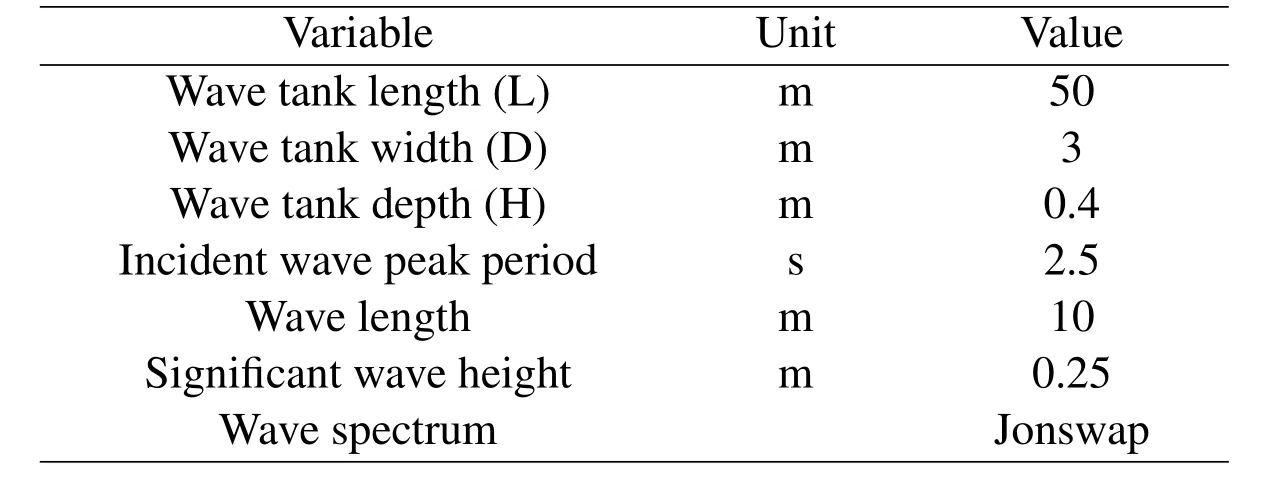
Table 1:Numerical Wave Tank Parameters
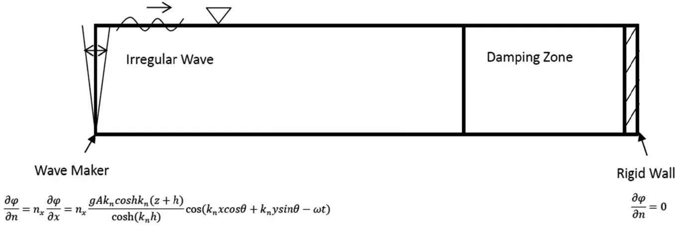
Figure 1:3D Numerical Wave Tank with Wave Maker
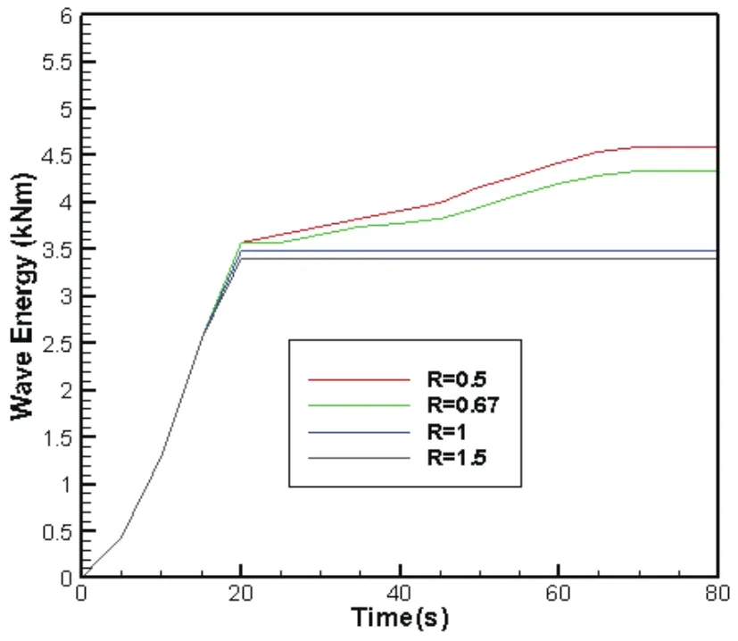
Figure 2:Comparison of Total Energy in Computational Domain among Different Damping Zone Size
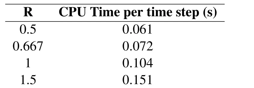
Table 2:Comparison of CPU Time for R=0.5,0.0067 1 and 1.5
4.2 Hybrid damping method
Toovercomethelargecomputationalcost,ahybridmethodisappliedanddiscussed for the fully nonlinear simulation.In this method,the radiation condition which is also known as the Sommerfeld condition is de fined at the end of the damping zone instead of rigid wall boundary condition[Contento and Casole(1995);Ma(1998)].In this method,the phase velocity c in the radiation condition is calculated based on the wave frequency of the wave with highest energy in order to damp the corresponding waves as shown in Fig.3 and Eq.21.

The damping zone size R is selected to be 0.5 with all other settings fixed as the optimized scheme from following sections.As shown in Fig.4,the wave energy calculated using damping zone method increases with time steadily.This indicates that the total energy accumulates in the domain and the poor wave absorption from the damping zone method.On contrast,the hybrid method performs very well as the total energy becomes steady as time grows.The next step is to optimize and exam the performance of the present method.There are several parameters need to be optimized for an ef ficient damping method such as the damping scheme inside damping zone,the associated ramp function,the damping strength coef ficient,the selection of the phase velocity c in the radiation condition at the right boundary and the damping zone sizes.These parameters will be discussed and compared in the following sections.

Figure 3:3D Numerical Wave Tank with Wave Maker and Radiation Condition
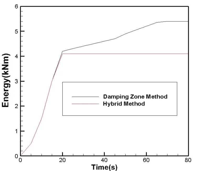
Figure 4:Comparison of Total Energy between Damping Zone Method and Hybrid Method
5 Optimization results
5.1 Effect of absorbing-beach schemes
For the damping schemes,two schemes of implementation are possible.The first kind is to put the damping term in dynamic free surface boundary condition as shown in Eq.22.Here P is the damping term and vanishes outside the absorbing zone.

Since the pressure acting on the free surface can take any form while the flow remains irrotational,it seems more appropriate to consider the additional term P as an additional pressure acting on the free surface.Then the energy transmission can be explained by the negative work done by the pressure P to the fluid via the free surface.The rate of energy absorption can be expressed as:

The other scheme is to put the damping term in the kinematic free surface boundary condition as shown in Eq.24 which contributes to change the dispersion relationship and the damping of the wave elevation.

P is often selected as P=−νη.Suppose a(linear)disturbance wave with wave amplitude A,wave frequency ω,and the wave number k(k= ω2/g)entering the damping zone.Its wave elvation could be written as:

By substituting the equation in the damped kinematic free surface boundary condition the result dispersion relation would be:

With ν>0.From the above dispersion relationship,the wave elevation could be written as:

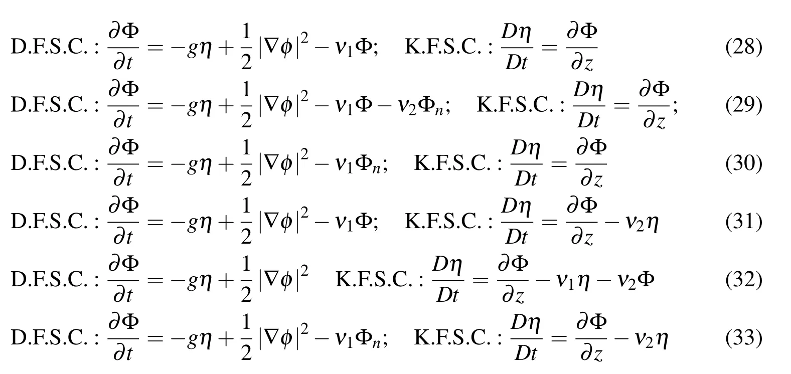
Based on the above two schemes,six different kinds of arti ficial damping schemes which are widely used in wave structure interaction problems are listed in Eq.28 to Eq.33.For example,in scheme 1,a Φ-type damping term is applied on the dynamic free surface boundary condition to damp the velocity potential with the choice as ν1= ν.Here ν is the damping coef ficient and its ramp function and associated damping parameter ν0will be discussed in the following sections.In scheme 2,there are two damping terms,which are Φ and Φntypes,applied on the dynamic boundary condition with ν1= ν and ν2= ν/k.Here k is selected to be the wave number calculated through the wave peak period.On the other hand,scheme 3 uses only one damping term,Φnwith ν1=kν,to the dynamic free surface boundary conditions.Scheme 4 applies two damping terms,η and Φ,to the kinematic and dynamic free surface boundary condition with the ν1= ν and ν2= ν.Scheme 5 also applies damping terms as η and Φ but only on the kinematic free surface conditions with ν1= ν/k and ν2= ν2/g.Scheme 6 uses Φnand η damping terms on the dynamic and kinematic free surface conditions with the ν1= ν/k and ν2= ν.In order to assess the performance of the above schemes,a test was done in the numerical wave tank by ‘QBEM’.
It should be noted that all possible combinations of the variables(e.g.free surface boundary conditions,ramp functions,damping parameters and phase velocity c)have been examined in the present study in order to find the most optimal damping hybrid schemes.However,for demonstration purpose,we only show the comparison results of each variable with all other variables fixed at the optimal values.For example,to compare the six damping schemes listed above,Fig.5(a)shows a comparison of the total wave energy in the computational domain calculated by various wave-absorbing schemes with the damping parameter ν0,damping zone length R and ramp functions chosen to be the best-performing ones which will be discussed in following section.From Fig.5,we can see that the absorbing–beach scheme 1,2,3 and 4 have too weak damping effect as the total energy in the computational domain calculated using these schemes increase with time.This indicates that the out-going and re flection are not fully absorbed and the poor performance of these schemes.On the other hand,the total energy calculated using scheme 5 and 6 becomes steady as time grows and no obvious growth is observed.These results indicate that these two schemes should be the favorable choice for the numerical study of the general wave-body interaction problems.Also,the wave elevations at the end of the damping zone are shown in the second Fig.5(b).The results using scheme 1,2and 3 are very closed so only numerical wave elevation from scheme 1 is shown in Fig.5(b)for demonstration.From comparison,it is seen that scheme 1,2,3 and 4 produce signi ficant wave re flection.On the contrast,the wave elevation in the end boundary calculated using scheme 5 and 6 is smaller than 10%of the incident wave amplitude(A=Hs/2).From detailed comparison,the energy calculated by scheme 6 becomes steady faster than scheme 5 and the wave re flection at the end is less signi ficant.Hence,we choose scheme 6 to be our optimal wave absorbing scheme inside the damping zone area.

Figure 5:(a)Comparison of Total Energy in Computational Domain among Different Damping Schemes(b)Time Histories of Wave Elevation at Computational Domain End Using Different Damping Schemes
5.2 Effect of numerical ramp function
It is well known that the magnitude of damping coef ficient ν should be controlled to change gradually along the damping zone.A proper choice of ramp function could prevent the abrupt change of the damping coef ficient ν which will induce the re flection of the incident wave at the entrance of the damping zone.As a result,a smooth ramp function is of major important for an ef ficient wave absorption method.In this study,four different ramp functions,which have been widely used in previous studies,are studied and compared in order to find an optimal ramp shape for the damping coef ficient.As shown in Eq.34 to Eq.37,Shape 1[Koo and Kim(2006)]used a cosine function which begins with a very small slope and gets steeper along the damping zone.Shape 2 increases quadratically along the damping zone by a second order function[Kim(1999)].Shape 3 uses the Hermite polynomial which has a very small entrance slope and increase fast inside in the damping zone.Sinusoidal function is used in shape 4 with the largest entrance slope compared to the other shape functions.The shapes of different ramp functions are shown in Fig.6.
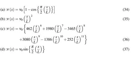
Fig.7 compares the total energy in the computational domain using four different ramp functions.Theoretically speaking,the wave damping performance would be better if the damping coef ficient area is larger.In that sense,the shape 4 is expected to have the best performance.However,from comparison,the total energy calculated using shape 4 increases steadily with time which indicates the poor performance of the ramp function 4.This may because that shape 4 has a large slope at the entrance of the damping zone and the incident will be re flected at the entrance.For demonstration,a regular wave train with wave period T=2.5 s and wave amplitude A=0.08 m is generated inside the wave tank.The wave elevation at the entrance of the damping zone is compared in Fig.8.As expected,shape 4 produces much larger re flection at the entrance due to its large entrance steepness while no signi ficant re flection wave is observed when using shape 1.So a ramp function which has a small entrance slope and larger damping capacity should be chosen for effective damping method.In that sense,shape 1 is the most suitable choice for our numerical wave absorption method.

Figure 6:Ramp Function Shapes
5.3 Effect of Numerical Damping Coef ficients
In this section,numerical damping coef ficient ν0used in Eq.33 to Eq.36 is optimized.In order to apply to more general cases,the optimization of ν0is conducted using non-dimensional parameters which are normalized by the wave tank depth H=1 m and gravitational constant g=9.8 m/s2.From previous study,it is well known that the numerical viscous coef ficient is directly related to the incident wave frequency[Ma(1988)].In order to optimize the parameter,the range of the peak frequency is selected in the range from 0 to 3 based on previous studies[Clement(1996);Ma(1998)].For each frequency,we select the best-performing damping coef ficient ν0based on the total energy in the computational domain and the wave elevation at the end of the tank.For example,Fig.9 plots the total energy and wave elevation and the end of the boundary for the case with ω=1.The comparison indicates that the damping zone performs best when the damping coef ficient ν0=0.05.
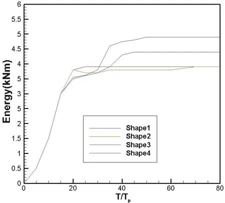
Figure 7:Comparison of Total Energy in Computational Domain among Different Ramp Functions
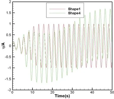
Figure 8:Time Histories of Wave Elevation at Entrance of Damping Zone using Regular Incident Wave(Comparison between Shape1 and Shape4)
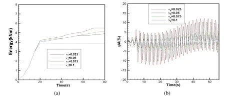
Figure 9:(a)Comparison of Total Energy in Computational Domain among Different Damping Coef ficients(b)Time Histories of Wave Elevation at Computational Domain End using Different Damping Coef ficients
Foreachincidentwavefrequency,sameoptimizationtestareconductedandFig.10 plots all the optimized damping coef ficients against the peak frequency of different incident waves.The discretize numerical value is then fitted by a fourth order polynomial and the optimized damping coef ficient is obtained by Eq.38.Here the wave frequency ω is chosen to be the incident wave peak frequency.It should be noted that for different wave period and wavelength,converge test of the wave tank length is conducted to make sure the damping zone is not impacted by the changing of the tank length.An example of these tests could be found in section 5.5.

Figure 10:Damping Coef ficient against Peak Frequency

Figure 11:Comparison of Total Energy in Computational Domain among Different Phase Velocities

5.4 Phase Velocity For Radiation Condition
With all other settings fixed,different phase velocities c in the boundary radiation condition(Eq.1)areimplementedwiththepurposeofinvestigatingtheeffectofthe phase velocity on the damping performance.The parameter c is again calculated using the wave frequency based on Eq.21.Fig.11 shows the time histories of total energy in the computational domain for different the phase velocities(c=cp,c=0.8cp,c=0.9cp,c=1.1cp,c=1.2cp).Here cpis corresponding to the phase speed calculated by incident wave peak period.As shown in the Fig.11,we can see that slight shift in the wave frequency makes little change of the energy growth as long as c is closed to cp(c=0.9cp,c=1.1cp).However,the energy calculated using phase velocity far away cp(c=0.8cp,c=1.2cp)increases as time grows which indicates the poor performance of the radiation condition at the boundary.From the optimization study,we could conclude that for an ef ficient wave damping method,phase velocity c need to be chosen in the range(0.9cp~1.1cp).
5.5 Effect of wave tank length
As pointed out by previous studies,the numerical wave tank length has a significant effect on the simulation results.For different incident waves in the present study,a convergence test of the wave tank length is conducted in order to make sure the numerical tank and the damping zone are working well before doing the detailed analysis and optimization studies.An example of these tests is shown in this section.Using fully nonlinear simulation with different wave tank lengths,convergence test is examined by comparing the wave history at the front of the damping zone.First,a regular wave train,with wave amplitude A=0.1 m and T=2.5 s,is simulated in this test.As shown in Fig.12(a),it is seen that for the wave tank length larger than three times of the incident wave length,no signi ficant difference is observed and the numerical results become converged as the wave tank length grows.It should be noted that the time“zero”in the Fig.12 is corresponding to the initial time when the incident wave train arrives at the damping zone.Same tests are also conduct for irregular waves with different peak periods Tp.Fig 12(b)plots the results using Tp=2.5 s.From comparison,same conclusion is drawn as the wave tank length should be at least three times longer than the wavelength λpwhich is calculated based on the incident wave peak period.The differences among the wave elevations using different tank lengths are mainly because of two reasons.First,the wave generated by the wave maker may interact with each other through nonlinear wave-wave interactions till they are fully developed and these interactions would change the wave pro file.The second reason comes from the in fluence of the transient wave which is generated at the wave maker and would decay only after traveling a relatively long distance.And it is known that the long wave components among these transient waves are very dif ficult to damp out using the numerical wave absorption method.From these numerical comparisons,we could conclude that the wave tank length should be at least three times larger than the incident wave length for a reliable numerical test.
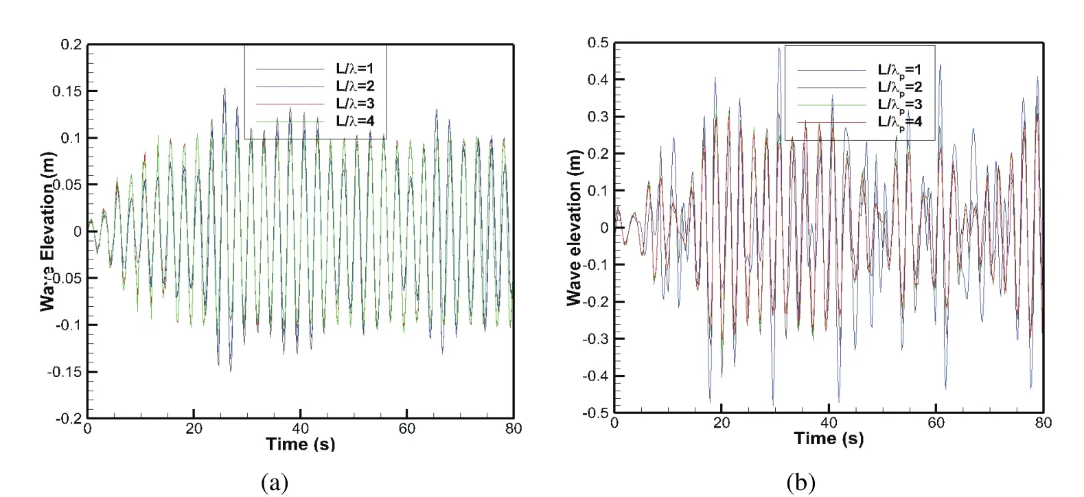
Figure 12:Effect of Tank Length(a)regular wave(b)irregular wave
6 Validation results
6.1 Comparison with wave tank experimental
To validate our hybrid wave absorption method,the numerical wave elevtion in the 3D numerical wave tank are first compared with the physical wave tank experiment from Zhao,Sun and Liang(2009).To be consistence with wave tank experiment,regular wave is used in the present case.The wave initial condition and wave tank dimensions are listed in Tab.3.Based on the experiment setup[Zhao,sun and Liang(2009)],there are totally eight wave gauges used to measure the water surface elevation along the wave tank.In order to validate the performance of the present method,the simulated and measured wave elevations at the second and fourth wave gauge are compared in Fig.13 to Fig.15 for the cases with different wavelengths.Good agreement between numerical and experiment data indicates the good performance of the numerical wave tank and numerical wave absorption method.The largest difference between the numerical simulation and experimental data is with 15%which is shown in Tab.4.
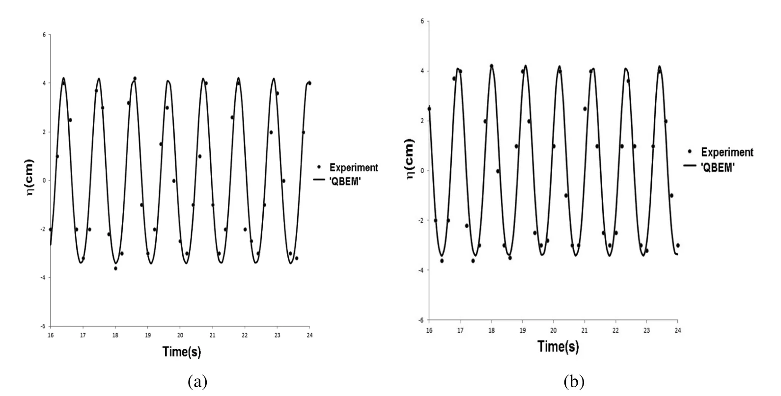
Figure 13:Wave Elevation Comparison at Second and Fourth Gauge(a)Gauge 2(b)Gauge 4(λ/H=4)
6.2 Cylinder free decay test
To validate ef ficiency of the optimized damping method,the optimized method is then used to study the practical fluid structure interaction problem.As shown in the Fig.16(a),a free decay problem of a floating cylinder is first considered.
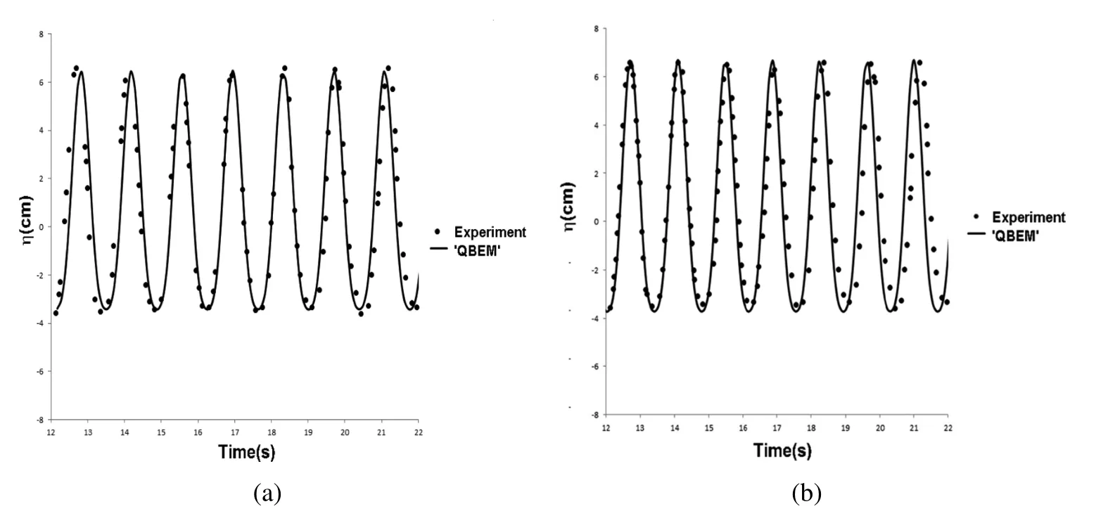
Figure 14:Wave Elevation Comparison at Second and Fourth Gauge(a)Gauge 2(b)Gauge 4(λ/H=6)

Figure 15:Wave Elevation Comparison at Second and Fourth Gauge(a)Gauge 2(b)Gauge 4(λ/H=8)
The cylinder is first hold in an unbalanced vertical positon and then a free decay motion is performed afterward.Fig.16(b)records the time history of the cylinder heave motion normalized by its initial displacement.In order to demonstrate the performance of the present method,we showed the results using damping scheme 1 shown in Eq.28 with all other settings fixed from the optimal values based on the previous sections.As shown in the Fig.16(b),it is seen that the body is impacted by the re flection wave when we use the damping scheme 1 while the re flection wave has very little impact to the body when the optimized scheme is applied.Asa result,the conclusion could be drawn that the optimized method has an excellent damping effect for the fluid structure interaction problems.

Table 3:Wave experiment parameters
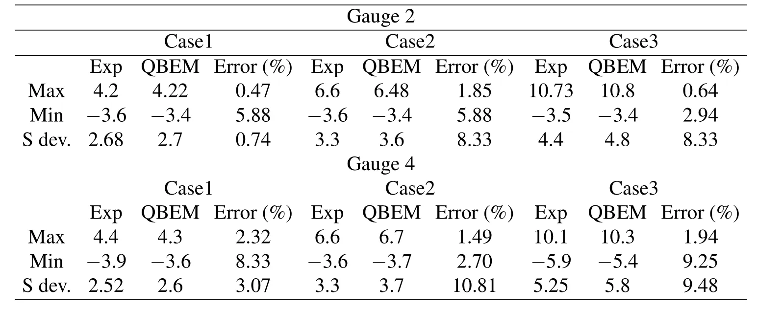
Table 4:Comparison between experiment and ‘QBEM’
6.3 Hydrodynamic modelling of a rigid body
Another test is done by the hydrodynamic modelling of a rigid body.The aim of this study is to simulate a body motion to a speci fic excitation in irregular waves and compare with experimental data.As shown in Fig.17,the device mainly consists of two major components:the device hull and mooring system.The hull has two main parts:a submerged horizontal cylinder with domed ends which was one diameter below the mean water free surface and two surface piercing columns extending from the model upwards through the free surface.The mooring system consists of two groups:vertical mooring lines between the cylinder and a moving clump mass and horizontal mooring lines restricting the clump mass to move in the heave direction only(see Fig.17).For all the experimental tests,the waves are unidirectional and the model orientation is set to ensure that the wave crest and the cylinder axis are parallel.The heave and surge mode motions of the device are dominant and will be used to justify the numerical damping method.As the prediction of the body motion requires an accurate prediction of the wave height andwaveforce,astrongre flectionwavefromtheboundarywouldhaveasigni ficant in fluence on the numerical results.Fig.18 and Fig.19 are the heave and surge motion of the numerical solutions comparing against the experiment results.From comparison,it is seen that the numerical solution is stable and is not in fluenced by the numerical boundary conditions.Detail geometry and experimental setups could be found in the study by Li and Liu(2015).

Figure 16:(a)Free Decay Cylinder in ‘QBEM’(b)Time Histories of Cylinder Motion:Comparison between Optimized Scheme and Damping Scheme 1
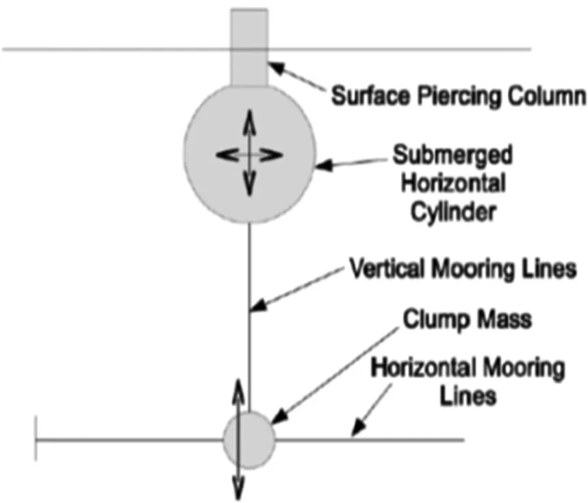
Figure 17:General Arrangement(side View)of the Device(Li and Liu,2015)
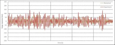
Figure 18:Comparison of the Surge Motion in Irregular Waves
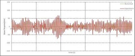
Figure 19:Comparison of the Heave Motion in Irregular Waves
7 Conclusion
In the present study,a hybrid wave absorption method which composes Sommerfeld radiation condition and numerical damping beach is applied.In order to assess the performance of this method,a 3D numerical wave tank is built in the numerical code‘QBEM’based on boundary element method.From fully nonlinear time domain test,the hybrid wave absorption method is found to preserve both the numerical accuracy and computation ef ficiency especially for long time numerical simulation of fluid-structure interactions.An optimized study is also conduct for the hybrid method.From comparison,the damping scheme using Φn−η type damping terms applied on free surface boundary conditions and ramp function with small entrance slope and enough damping capacity has the best damping perfor-mance.In addition,the phase velocity used in the radiation condition,the damping parameter υ0and the damping zone size are also investigated and optimized in the present study.To validate our method,the numerical wave making problem,cylinder free decay test and numerical prediction of a floating body under irregular waves are conduct and compared with the available experiment data.Good agreement between experiments and fully-nonlinear simulation and the fast computational speed suggest that the optimized hybrid wave absorption method is the most suitable method for the numerical fluid structure interaction problem.
Acknowledgement:The author would like to express thanks to Prof.Qingwei Ma from City University London and Prof.Lixin Xu from Tianjin University for their valuable discussion and advice during the International Conference of Computational&Experimental Engineering and Sciences,2015.
Arai,M.,;Paul,;U.K.,Cheng,L.Y.,;Inoue,Y.(1993):A technique for open boundary treatment in numerical wave tanks.Journal of The Society of Naval Architects of Japan.vol.173,pp.45-50.
Atluri,S.N.,;Zhu,T.(1998):A new meshless local Petrov-Galerkin(MLPG)approach in computational mechanics.Comput.Mech.,vol.22,pp.117-127.
Atluri,S.N.,;Shen,S.(2002):The Meshless Local Petrov-Galerkin(MLPG)Method:A Simple&Less-costly Alternative to the Finite Element and Boundary Element Methods.CMES:Computer Modeling in Engineering&Sciences,vol.3(1),pp.11-52.
Baker,G.R.,;Meiron,D.I.,;Orszag,S.A.(1982):Generalized vortex methods for free-surface flow problems.Journal of Fluid Mechanics,vol.123,pp.477-501.Celebi,M..,;Kim,M.H.(1991):Nonlinear wave-body interactions in a numerical wave tank.12thinternational Workshop on Water Waves and Floating Bodies,Carry-le-Rouet,France.
Clément,A.(1996): Coupling of two absorbing boundary conditions for 2D time-domain simulations of free surface gravity waves.Journal of Computational Physics,vol.126,pp.139-151.
Clément,A.,;Domgin,J.F.(1995):Wave absorption in a 2D numerical wave basin by coupling two methods.In Proceedings of the International Workshop of Water Waves and Floating Bodies,Oxford(pp.15-20).
Contento,G.;Casole,S.(1995):On the generation and propagation of waves in 2D numerical wave tanks.In The Fifth International Offshore and Polar Engineering Conference.International Society of Offshore and Polar Engineers.
Cointe,R.,;Geyer,P.(1991): Nonlinear and linear motions of a rectangular barge in a perfect fluid.Proc.18thSymp.Naval Hydro.Univ.of Michigan,Ann Arbor,pp.85-98.
Ferrant,P.(1994):Radiation and diffraction of nonlinear waves in three dimensions.BOSS,MIT,pp.507-524.
Grilli,S.T.,;Horrillo,J.(1997):Numerical generation and absorption of fully nonlinear periodic waves.Journal of Engineering Mechanics,vol.123(10),pp.1060-1069.
Hong,S.Y.,;Kim,M.H.(2000): Nonlinear wave forces on a stationary vertical cylinder by HOBEM-NWT.In The Tenth International Offshore and Polar Engineering Conference.International Society of Offshore and Polar Engineers.Israeli,M.,;Orszag,S.A.(1981).Approximation of radiation boundary conditions.Journal of Computational Physics,vol.41,pp.115-135.
Kim,M.W.;Koo,W.;Hong,S.Y.(2014):Numericalanalysisofvariousarti ficial damping schemes in a three-dimensional numerical wave tank.Ocean Engineering,vol.75,pp.165-173.
Kim,Y.(1999): computation of higher order hydrodynamic forces on ships and offshore structures in waves.Doctoral dissertation,Massachusetts Institute of Technology.
Kim,Y.(2003):Arti ficial damping in water wave problems II:application to wave absorption.International Journal of Offshore and Polar Engineering,vol.13.
Koo,W.,;Kim,M.H.(2004): Freely floating-body simulation by a 2D fully nonlinear numerical wave tank.Ocean Engineering,vol.31(16),pp.2011-2046.
Li,C.;Liu,Y.(2015): Fully-Nonlinear Simulation of the Hydrodynamics of a Floating Body in Surface Waves by a High-Order Boundary Element Method.Offshore Mechanics and Arctic Engineering Conference OMAE 2015,St.John’s Newfoundand,May 31-June 5.
Lin,W.M.;Newman,J.N.;Yue,D.K.(1984):Nonlinear forced motions of floating bodies.In Proceedings of the 15th Symposium on Naval Hydrodynamics,pp.33-47.
Liu,P.L.F.;Liggett,J.A.(1983):Applications of boundary element methods to problems of water waves.Developments in Boundary Element Methods,vol.2,pp.37-67.
Liu,Y.;Xue,M.;Yue,D.K.(2001): Computations of fully nonlinear threedimensional wave–wave and wave–body interactions.Part 2.Nonlinear waves and forces on a body.Journal of Fluid Mechanics,vol.438,pp.41-66.
Longuet-Higgins,M.S.;Cokelet,E.D.(1976):The deformation of steep surface waves on water.I.A numerical method of computation.In Proceedings of the Royal Society of London A:Mathematical,Physical and Engineering Sciences,vol.350,no.1660,pp.1-26.
Ma,Q.(1998):Numerical simulation of nonlinear interaction between structures and steep waves.Doctoral dissertation,University of London.
Ma,Q.(2005):MLPG method based on rankine source solution for simulating nonlinear water waves.CMES:Computer Modelling in Engineering&Sciences,vol.9,pp.193-209.
Nestegard,A.;Sclavounos,P.D.(1984): A numerical solution of twodimensional deep water wave-body problems.Journal of ship research,vol.22,pp.48-54.
Newman,J.N.(1977):Marine hydrodynamics.MIT press.
Ohyama,T.,;Nadaoka,K.(1991):Development of a numerical wave tank for analysis of nonlinear and irregular wave field.Fluid Dynamics Research,vol.8,pp.231.
Okada,H.,;Rajiyah,H.,;Atluri,S.N.(1988):A novel displacement gradient boundary element method for elastic stress analysis with high accuracy.Journal of applied mechanics,vol.55,pp.786-794.
Okada,H.,;Rajiyah,H.,;Atluri,S.N.(1989): Non-hyper-singular integralrepresentations for velocity(displacement)gradients in elastic/plastic solids(small or finite deformations).Computational mechanics,vol.4,pp.165-175.
Okada,H.,;Rajiyah,H.,;Atluri,S.N.(1990):A full tangent stiffness fieldboundary-element formulation for geometric and material non-linear problems of solid mechanics.International journal for numerical methods in engineering,vol.29,pp.15-35.
Okada,H.,;Atluri,S.N.(1994):Recent developments in the field-boundary element method for finite/small strain elastoplasticity.International journal of solids and structures,31(12),1737-1775.
Orlanski,I.(1976): A simple boundary condition for unbounded hyperbolic flows.Journal of computational physics,vol.21,pp.251-269.
Sommerfeld,A.J.W.(1949):Partial differential equations in physics.Academic press.
Tanizawa,K.,;Naito,S.(1997): A study on parametric roll motions by fully nonlinear numerical wave tank.In The Seventh International Offshore and Polar Engineering Conference.International Society of Offshore and Polar Engineers.
Uzair,A.S.,;Koo,W.(2012):Hydrodynamic analysis of a floating body with an open chamber using a 2D fully nonlinear numerical wave tank.International Journal of Naval Architecture and Ocean Engineering,vol.4,pp.281-290.
Wang,P.,Yao,Y.,;Tulin,M.P.(1995):An ef ficient numerical tank for nonlinear water waves,based on the multi-subdomain approach with BEM.International journal for numerical methods in fluids,Vol.20,pp.1315-1336.
Yan,S.,;Ma,Q.,;Cheng,X.(2012):Numerical investigations on transient behaviours of two 3-D freely floating structures by using a fully nonlinear method.Journal of Marine Science and Application,vol.11(1),pp.1-9.
Yen,S.M.;Hall,D.R.(1981):Implementation of open boundary conditions for nonlinear free-surface wave problems.In Proc.of 3rd Int.Conf.on Numerical Ship Hydro.,pp.163-176.
Zhao,X.Z.;Sun,Z.C.;Liang,S.X.(2009):A numerical study of the transformation of water waves generated in a wave flume.Fluid dynamics research,vol.41,035510.
Zhang,J.D.,;Atluri,S.N.(1986):Non-linear quasi-static and transient response analysis of shallow shells:Formulations and interior/boundary element algorithms.Boundary Elements,87-109.
Zhang,J.D.,;Atluri,S.N.(1988):Post-buckling analysis of shallow shells by the field-boundary-element method.International Journal for Numerical Methods in Engineering,vol.26(3),pp.571-587.
1Massachusetts Institute of Technology,Cambridge,MA,USA
 Computer Modeling In Engineering&Sciences2015年20期
- Computer Modeling In Engineering&Sciences的其它文章
- A Micromechanical Model for Estimating the Effective Stiffness of a Pair of Micro-cracked Interfaces in an Orthotropic Trimaterial under Inplane Deformations
- Real-Time Moving Targets Detection in Dynamic Scenes
- Are Higher-Order Theories and Layer-wise Zig-Zag Theories Necessary for N-Layer Composite Laminates?
