A Micromechanical Model for Estimating the Effective Stiffness of a Pair of Micro-cracked Interfaces in an Orthotropic Trimaterial under Inplane Deformations
,2
A Micromechanical Model for Estimating the Effective Stiffness of a Pair of Micro-cracked Interfaces in an Orthotropic Trimaterial under Inplane Deformations
X.Wang1,W.T.Ang1,2,H.Fan1
Amicromechanicalmodelisproposedhereforestimatingtheeffective stiffness of a pair of parallel microscopically damaged interfaces in a trimaterial under inplane elastostatic deformations.The trimaterial is made of an orthotropic thin layer sandwiched between two orthotropic half-spaces.The microscopically damaged interfaces are modeled using periodically distributed interfacial micro-cracks.The micromechanical model is formulated and numerically solved in terms of hypersingular boundary integro-differential equations.The effects of the width of the thin layer,the micro-crack densities of the two interfaces and the material constants of the thin layer and the two half-spaces on the effective stiffness coef ficients are investigated.
Micromechanics;Microscopically damaged interface;Effective stiffness coef ficients;Trimaterial;Thin film;Hypersingular integral and integrodifferential equations.
1 Introduction
Multilayered structures are widely used in microelectromechanical devices such as micro-sensors and actuators(Muralt(2000)).During the fabrication of such structures,micro-cracks may be formed on the interface between two dissimilar layers due to mismatch in the thermal and mechanical properties of the layers or micro-roughness of surfaces.
For a simpli fied analysis of multilayered materials,a micro-cracked interface may be modeled asa continuous distribution ofsprings characterizedby aset ofstiffness coef ficients.As in Benveniste and Miloh(2001),the tractions on the spring-like interface are linearly related to the jump in the displacements across opposite sidesof the interface,that is,if the spring-like interface between two dissimilar materials referred to as 1 and 2 is denoted by Γ then the interfacial conditions are given by

whereis the unit normal vector to Γ pointing into material 1,andare respectively the displacement( first order tensor)and the stress(second order tensor)in material i andis the stiffness(second order tensor)of Γ.
The spring-like interface de fined by(1)was used by many researchers for analyzing multilayered materials with imperfect weak interfaces(see,for example,Ang(2007),Fan and Wang(2003),Jones and Whittier(1967),Margetan,Thompson and Gray(1988)and Sudak and Wang(2006)).There are,however,very few papers that estimate the stiffnessby considering the micro details of the interface.
To estimate the effective stiffness of a micro-cracked interface between two halfspaces,Fan and Sze(2001)proposed a finite element based three-phase model in which the interface was modeled by a representative micro-crack interacting with spring-like effective regions with an unknown stiffness.The micro-crack details captured in the highly simpli fied three phase model were the average micro-crack length and the micro-crack density.More recently,Wang,Ang and Fan(2012)and Wang,Fan and Ang(2014)estimated the effective stiffness by simulating statistically the interfacial micro-cracks between two anisotropic elastic half-spaces under antiplane deformations.The positions and the lengths of the micro-cracks were randomly chosen.The micromechanical-statistical approach in Wang,Ang and Fan(2012)and Wang,Fan and Ang(2014)was also used in Wang,Ang and Fan(2015)to compute the effective stiffness of a micro-cracked interface between an orthotropic thin layer and an orthotropic half-space under inplane deformations.The current paper proposes a micromechanical model for the estimation of the effective stiffness of a pair of parallel micro-cracked interfaces in a trimaterial under inplaneelastostaticdeformations.Thetrimaterialismadeofanorthotropicthinlayer sandwiched between two orthotropic half-spaces.The micro-cracks on the parallel plane interfaces are periodically distributed.The micro-crack density of one of the interfaces may be different from that of the other interface.The task of calculating the effective stiffness of the micro-cracked interfaces is eventually reduced to solving numerically a system of hypersingular boundary integro-differential equations.The effects of the width of the thin layer,the micro-crack densities of the two interfaces and the material constants of the thin layer and the two half-spaces on the effective stiffness coef ficients are investigated in some details.
The hypersingular integral approach is widely used for solving elastic crack problems(seeAng(2013),PurbolaksonoandAliabadi(2005),Sanz,SolisandDominguez(2007)and other references therein).It is advantageous for use here as the crackopening displacements which are required in computing the effective stiffness of themicro-crackedinterfacesappeardirectlyinthehypersingularintegro-differential equations for the conditions on the micro-cracks.
2 Statement of the micromechanical problem
With reference to a Cartesian coordinate system Ox1x2x3,consider a thin elastic layer in the region 0<x2<h sandwiched between two elastic half-spaces which occupy the regions x2<0 and x2>h.The materials in the layer and the two half-spaces are orthotropic,having possibly dissimilar elastic properties.The plane interfaces x2=0 and x2=h between the layer and the half-spaces are denoted by I and II respectively.
Each of the interfaces contains a periodic distribution of micro-cracks which have the geometries independent of the x3coordinate.More speci fically,the microcracks on interface I lie in the regions

and those on interface II lie in

where L is the length of a period interval of the micro-cracked interface,andare real numbers such thatand.Thus,interfaces I and II contain periodic arrays of evenly distributed micro-cracks of length 2aIand 2aIIrespectively,whereandThe materials in the layer and the half-spaces are assumed to be perfectly bonded on the uncracked parts of the interfaces.Refer to Fig.1 for a geometrical sketch of the trimaterial.
The damage ratios ρIand ρIIwhich give the micro-crack densities of interfaces I and II are de fined as follows:

The trimaterial undergoes an inplane elastostatic deformation governed by the partial differential equations

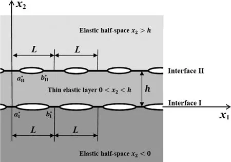
Figure 1:A geometrical sketch of the trimaterial and the micro-cracked interfaces
where u1(x1,x2)and u2(x1,x2)are the x1and x2Cartesian components of the displacement andC11(x2),C12(x2),C22(x2)and C66(x2)are elastic moduli de fined by


for all real numbers ξ1,ξ2and ξ3such that
For theorthotropictrimaterial,ifthemicro-crackedinterfacesIandIIaresimpli fied as spring-like interfaces then the interfacial conditions on x2=0 and x2=h are respectively given by

and

where krIand krII(r=1,2)are the effective stiffness coef ficients of interfaces I and II respectively and σkjare the Cartesian components of the stress.For the springlike interfaces given by(6)and(7)to be valid,the remote external tensile load acting on the trimaterial along the x2direction is assumed to be suf ficiently large(dominant).The micro-cracks are assumed to be traction free under the remote external load.
The problem is to estimate the effective stiffness coef ficients krIand krIIand to investigate the effects of the width h of the layer,the damage ratios ρIand ρIIand the elastic modulion krIand krII.
3 Boundary value problem
The boundary value problem to solve for estimating the effective stiffness coef ficients krIand krIIof interfaces I and II is stated below.
The displacement ukand the stress σkjin the trimaterial are written as

Thus,the conditions on the micro-cracked interfaces I and II are given by

where CIand CIIdenote the micro-cracked parts of interfaces I and II respectively,PIand PIIdenote the perfectly bonded parts of interfaces I and II respectively,andandare respectively the displacement jumps(over interfaces I and II).
As the micro-cracks are periodically distributed on x2=0 and x2=h as described in Section 2,the loadsandon the micro-cracks are assumed to be periodic functions of x1with period L.They may be chosen to be constant functions.With such periodic loads on the periodically distributed interfacial micro-cracks,ukand σkjare periodic functions of x1with period L.Thus,the boundary value problem is to solve the equilibrium equations in(3)forsubject to the interfacial conditions in(9).In addition to(9),it is required thatas
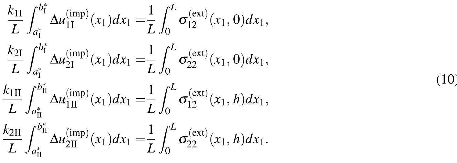
Once the boundary value problem is solved,the effective stiffness coef ficients krIand krIIof the micro-cracked interfaces by averaging the crack-opening displacements and the external stress on the interfaces,that is,via the formulae:
4 Hypersingular boundary integro-differential equations
To formulate the boundary value problem in Section 3 in terms of hypersingular boundary integral equations,the trimaterial in Fig.1 is divided into two subdomains x2>h/2 and x2<h/2 along the arti ficial plane boundary x2=h/2.Each of the subdomains may be regarded as a bimaterial consisting of a thin elastic layer and an elastic half-space.The boundary integral equations in Clements(1981)together with the perfect interface Green’s function given in Berger and Tewary(2001)and Chen and Ang(2014)for a bimaterial are used to obtain the hypersingular integral and integro-differential equations separately for each of the two subdomains.The analysis in Wang,Ang and Fan(2015)is closely followed here to derive the hypersingular boundary integral equations.
From the analysis on the lower subdomain x2< h/2,the stresson the arti ficial boundary x2=h−/2 is given by the hypersingular boundary integral equations

and the conditions on interface I,as given in(9),may be expressed in terms of the hypersingular boundary integro-differential equations
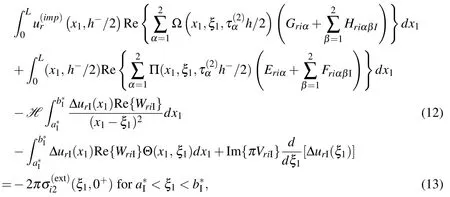


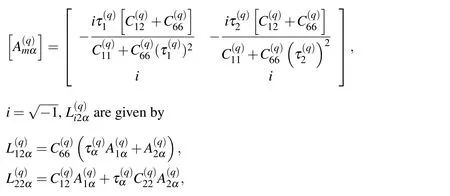


δipis Kronecker-delta,Im denotes the imaginary part of a complex number,the constantsare implicitly de fined by(see Chen and Ang(2014))

and the functions Λ(x1,ξ1),Π(x1,ξ1,z),Θ(x1,ξ1)and Ω(x1,ξ1,z)are de fined by

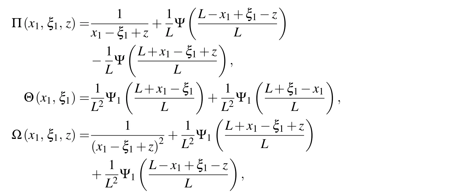
with Ψ(z)and Ψ1(z)being the digamma and trigamma functions respectively(see Abramowitz and Stegun(1970)).Note that the usual Einsteinian convention of summing over a repeated index is applicable here only for lowercase Latin subscripts from 1 to 2.
Similarly,from the analysis on the upper subdomain x2> h/2,the stresson the arti ficial boundary x2=h+/2 is given by the hypersingular boundary integral equations
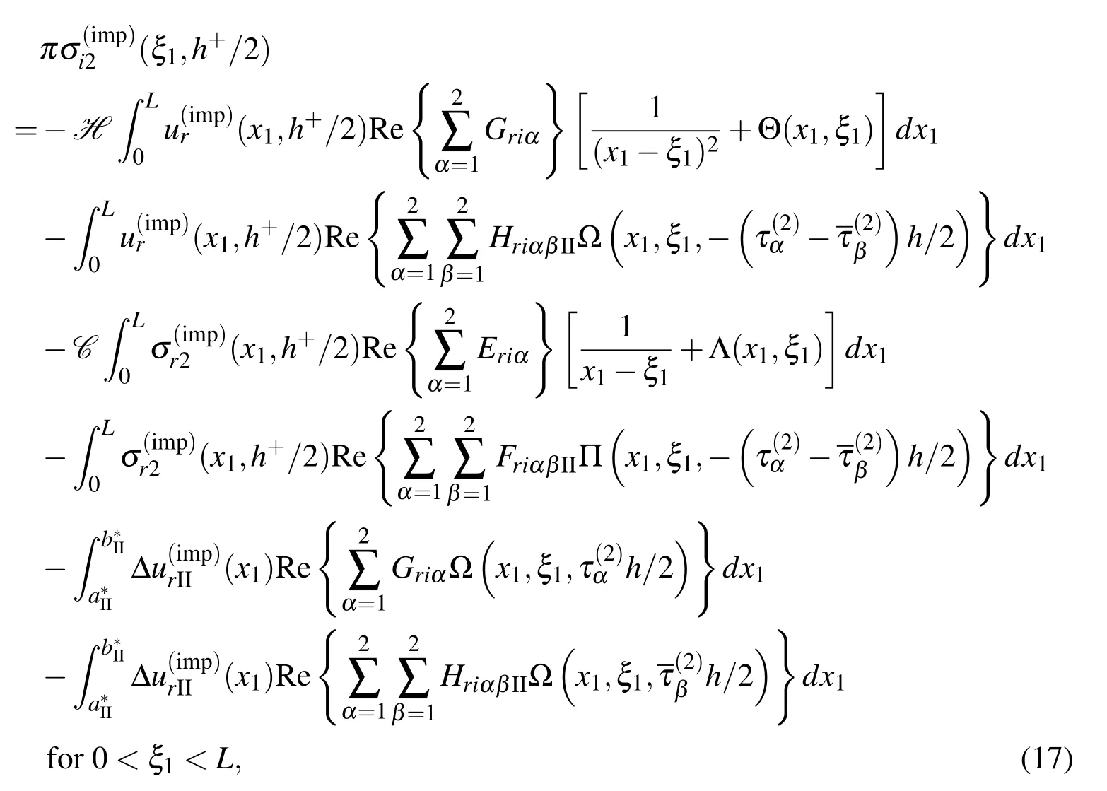
and the conditions on interface II may be expressed in terms of the hypersingular boundary integro-differential equations
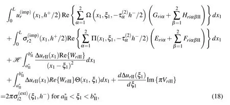
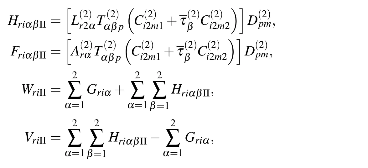
where HriαβII,FriαβII,WriIIandVriIIare given by

Note that(11),(12),(16)and(17)do not contain any integral over the perfect(uncracked)parts of interfaces I and II because of the use of the special perfect interface Green’s function given in Berger and Tewary(2001)and Chen and Ang(2014).
In(11),(12),(16)and(17),there are 12 unknown functions given by the displacementsthe stressesh−/2)and the crack opening displacementsandon interfaces I and II respectively.However,there are only 8 equations in(11),(12),(16)and(17).Four more equations are required to complete the formulation.They are given by the continuity conditions on the arti ficial boundary x2=h/2 as follows:

5 Numerical procedure
Thenumericalprocedureforsolvingthehypersingularintegralandintegro-differential equations(11),(12),(16)and(17)together with(19)is outlined below.
The part of the arti ficial boundary x2=h/2 where 0≤x1≤L is discretized into Ntequal subintervals given by


To generate 8Ntequations,the hypersingular integral equations(11)and(16)may be collocated at two points per subinterval over the region where 0<x1<L,x2=h/2.The two collocations points on the p-th subinterval are chosen to be

AsinKayaandErdogan(1987),theunknowncrackopeningdisplacementsandon interfaces I and II respectively may be approximated by using


The hypersingular integro-differential equations(12)and(17)may be collocated at NcIand NcIIpoints respectively to generate NcI+NcIIequations.The collocation points overare chosen to be given by


If the approximations in(20),(22)and(23)are substituted into hypersingular boundary integro-differential equations(11),(12),(16)and(17)collocated at the relevant collocation points de fined by(21),(24)and(25)and if the continuity conditions(19)is used,a system of linear algebraic equations may be set up to determine the 8Nt+NcI+NcIIunknown constants in(20),(22)and(23).Onceandare obtained,the effective stiffness coef ficients krIand krIImay be easily computed by substituting(22)and(23)into(10).
6 Speci fic cases
Some speci fic cases of the problem are examined here by using particular orthotropic materials.The materials and their elastic moduli(in GPa)(taken from Glodež and Jezernik(2010),Guechaichia and Trenda filova(2012)and Rubio-Gonzalez and Mason(2000))are given in Tab.1.
Case(a):The interface II is taken to be perfect,that is,ρII=0.The materials in the layer and the lower half-space are carbon-epoxy and graphite-epoxy respectively.The elastic moduli(in GPa)of the material in the upper half-space are chosen to be


Table 1:Elastic moduli(in GPa)for selected orthotropic materials.
where α is a positive constant.
If α is very small,the material in the upper half-space is extremely soft compared to the materials in the layer and the lower half-space.Thus,the limiting case in which α→0+gives a micro-cracked interface between an elastic half-space and a thin layer with one of its edges acted upon by prescribed tractions,as considered in Wang,Ang and Fan(2015).
If α=1,the upper half-space and the layer are both occupied by carbon-epoxy.Since the interface II is perfect,α=1 corresponds to the special case of a microcracked interface(given by interface I)between two dissimilar homogeneous elastic half-spaces.Such a special case can also be recovered from the analysis here for any other value of α by letting the width of the layer tend to in finity.
For ρI=0.5,the non-dimensionalized effective stiffness coef ficientsandareplottedagainstaI/hforselectedvaluesofα.Thegraphsofandfor the special case α → 0+,obtained by using the analysis Wang,Ang and Fan(2015),are also given in Fig.2.It is obvious that the graphs ofandfor smaller values of α are closer to those for α → 0+.This gives a check for the analysis here against the one in Wang,Ang and Fan(2015).
For a fixed α,the non-dimensionalized effective stiffness coef ficientsandin Fig.2 are observed to decrease and increase as aI/h increases for α < 1 and α > 1 respectively.This observation may be explained as follows.The perfectly bonded thin layer and the upper half-space may be considered as a“combined half-space”.For α < 1,the upper half-space is softer than the thin layer.Thus,the “combined half-space”becomes softer as the thin layer width decreases(thatis,asaI/hincreases),givinglargeraveragevaluesofoverinterface I for larger aI/h.For α>1,the upper half-space is harder than the thin layer and hence the average values ofover interface I are smaller for larger aI/h.
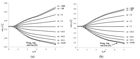
Figure 2:Plots ofandagainst aI/h for the cases where interface II is perfectly bonded with and selected values of α
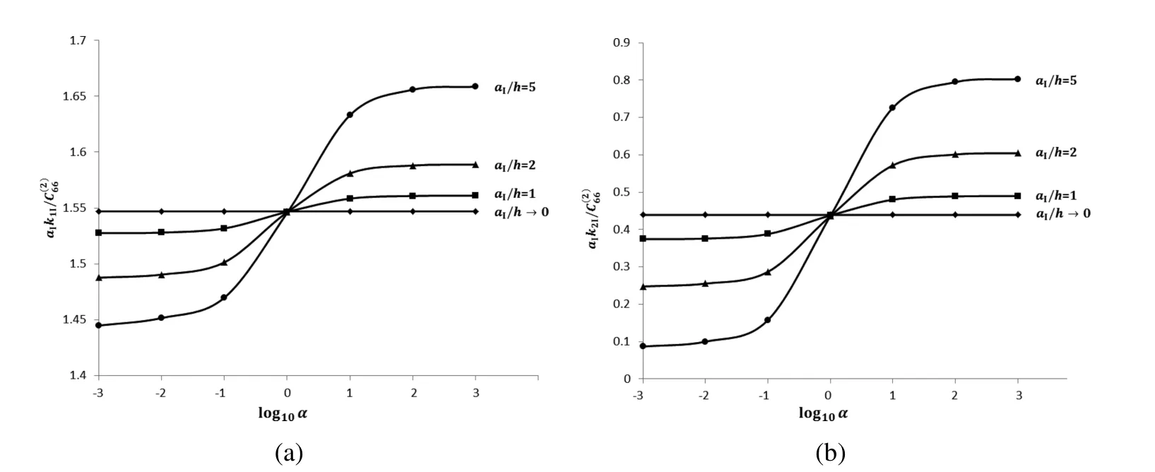
Figure 3:Plots ofand against log10α for the cases where interface II is perfectly bonded with ρI=0.5 and selected values of α
For a fixed value of aI/h,Fig.2 shows thatandbecome larger as α increases.For the limiting case in which α → ∞,the layer is perfectly bonded to a rigid wall along the plane x2=h(so that u1=u2=0 on x2=h).It may be of some interest to examine in details howandvary with α for a fixed value of aI/h.For ρI=0.5,Fig.3 plotsandagainst log10α for selected values of aI/h.From the graphs for a given aI/h,it is apparent thatandtend to some constant values as
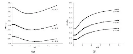
Figure 4:Plots of ak1/C66and ak2/C66against a/h for ρ=0.4,0.5 and 0.6
Case(b):The thin layer and the two half-spaces are occupied by the same orthotropic material.The material is taken to be graphite-epoxy.The interfaces are taken to be identical,so that ρI= ρII= ρ,hence aI=aII=a,where a and ρ are constants such that ρ=2a/L.For such a case,the effective stiffness coef ficients are such that k1I=k1II=k1and k2I=k2II=k2.
In Fig.4,the non-dimensionalized effective stiffness coef ficients ak1/C66and ak2/C66are plotted against a/h for selected values of ρ.Note that C66=7.5 GPa for graphite epoxy.For a given value of ρ,non-dimensionalized effective stiffness coef ficient ak1/C66is observed to have a local minimum at a certain value of a/h.The value of a/h where the local minimum of ak1/C66occurs appears to increase with ρ.
Also,for a given ρ,the non-dimensionalized effective stiffness coef ficient ak2/C66appears to increase as a/h increases.This may be explained by taking into consideration the crack shielding effect described in Gao,Lee and Zhou(2012),that is,for two parallel cracks in a homogeneous elastic space under remote pure tensile load,the crack opening displacementof each of the cracks decreases as the cracks gets closer to each other.
For a given value of a/h,it appears that ak1/C66and ak2/C66have larger values for smaller values of ρ.This is not surprising as the micro-cracks are more stable and have smaller crack opening displacements if the micro-cracks have lower density on the interfaces.Case(c):As in Case(b),the layer and the half-spaces are occupied by graphiteepoxy.However, ρIand ρIIare not necessarily equal here.For such a case,it may be more instructive to non-dimensionalize the effective stiffness coef ficients as(aI+aII)krI/(2C66)and(aI+aII)krII/(2C66).
For ρI=0.5,the non-dimensionalized effective stiffness coef ficients(aI+aII)krI/(2C66)and(aI+aII)krII/(2C66)are plotted against(aI+aII)/(2h)for selected values of ρIIin Figs.5 and 6 respectively.As expected,Figs.5 and 6 show that the graph of(aI+aII)krI/(2C66)is the same as that of(aI+aII)krII/(2C66)for ρII=0.5(that is,when interfaces I and II have the same damage ratio).For ρI=0.5 and given values of ρIIand(aI+aII)/(2h),Figs.5 and 6 show that krI< krIIfor ρII< 0.5 and krI> krIIfor ρII> 0.5.This observation is as expected because of the following reason.For ρII< 0.5,interface II is less severely damaged than interface I(ρI=0.5),hencemay be expected to be less thanto give krII> krI.Similarly,for ρII> 0.5,with interface II more severely damaged,is greater thanhence krII< krI.
In Fig.5,the range of values which the non-dimensionalized effective stiffness coef ficients(aI+aII)k1I/(2C66)and(aI+aII)k2I/(2C66)(for interface I)can have over the interval 0<(aI+aII)/(2h)≤5 is narrower if ρIIhas a smaller value.Thus,one may expect(aI+aII)k1I/(2C66)and(aI+aII)k2I/(2C66)to tend to parameters that are independent of(aI+aII)/(2h)as ρII→ 0.This observation is consistent with the fact that the effective stiffness coef ficients of interface II are independent of the width of the layer if interface II is perfect(ρII=0)and the layer and the upper half-space are occupied by the same material.
For ρI=0.5 and a given value of(aI+aII)/(2h),Fig.6 shows that the values of
(aI+aII)k1II/(2C66)and(aI+aII)k2II/(2C66)increase as ρIIdecreases to zero.This is as expected since both k1IIand k2IIshould tend to in finity as ρIItends to zero,that is as interface II approaches being perfect.From Fig.6,it is also apparent that(aI+aII)k2II/(2C66)increases with(aI+aII)/(2h)at a faster rate for a smaller value of ρII.
Case(d):The thin layer is occupied by graphite-epoxy.The material in the upper half-space is taken to be the same as that in the lower half-space.One of the following materials—martensite,graphite-epoxy and e-glass-epoxy—is selected to occupy the half-spaces.As in Case(a)above,the interfaces are such that ρI=ρII=ρ and aI=aII=a,hence k1I=k1II=k1and k2I=k2II=k2.
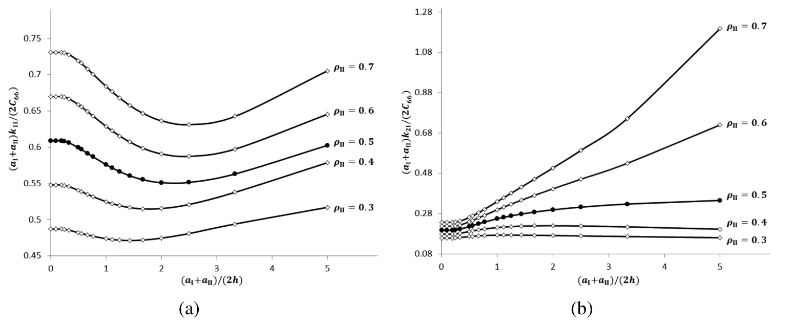
Figure 5:Plots ofandagainst(aI+aII)/(2h)for selected values of ρII
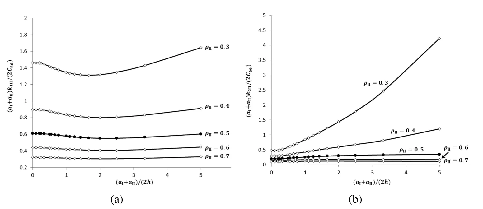
Figure 6:Plots ofandagainst(aI+aII)/(2h)for selected values of ρII
For ρ=0.5,Fig.7 plots the non-dimensionalized effective stiffness coef ficientsagainst a/h for selected materials in the half-spaces.Note that the thin layer and the half-spaces are occupied by the same materials if the elastic moduli of graphite-epoxy are used for the half-spaces.Fig.7(a)shows that,as a/h increases,increases if the half-spaces are occupied by martensite,butbecomes smaller if the half-spaces are occupied by e-glass-epoxy.In Fig.7(b),the rate of increase inwith increasing a/h is the most drastic when the half-spaces are occupied by martensite.For a given a/h,Fig.7 shows that the values of the effective coef ficients for graphite-epoxy half-spaces are respectively smaller and larger than those for martensite and e-glass-epoxy half-spaces.
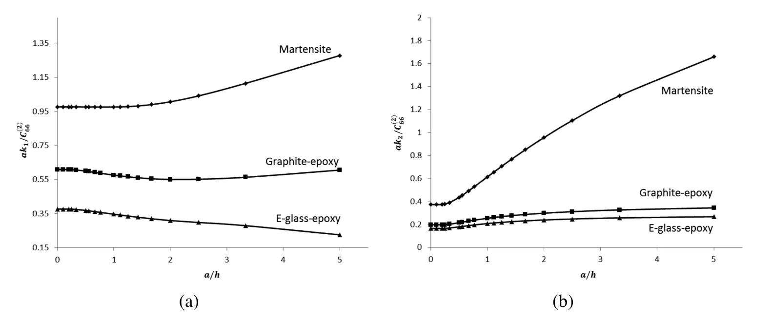
Figure 7:Plots of andagainst a/h for the cases where martensite,graphite-epoxy and e-glass-epoxy are used as the material of the half-spaces
The observations above on the effective stiffness coef ficients can be explained by noting the relative strength of the three materials selected for the analysis here.Martensite is the hardest of the three materials,whereas e-glass-epoxy is the softest.Thus,when the half-spaces are occupied by martensite,the trimaterial on the whole becomes stronger and the micro-cracks on the interfaces have relatively smaller displacement jumps over the micro-cracks,as a/h increases(that is,as the width of the layer decreases).At the same time,as a/h increases,the jump in the displacement u2over the micro-cracks also become smaller due to the shielding effect of parallel micro-cracks as explained in Case(b).All this combines to increase the effective stiffness coef ficient k2of the interfaces drastically when the half-spaces are occupied by martensite.When the half-spaces are occupied by graphite-epoxy which is also the material in the layer,only the shielding effect of the parallel micro-cracks contributes to increasing the effective stiffness coef ficient k2as a/h increases.For e-glass-epoxy half-spaces,increasing a/h has the effect of weakening the overall strength of the trimaterial,hence decreasing the effective stiffness coef ficients.However,as shown in Fig.7(b)for e-glass-epoxy,the effective stiffness k2may still increase with increasing a/h if the micro-crack shielding effect in increasing k2is more dominant than the opposing effect caused by the weakening of the trimaterial.
7Summary
The present paper proposes a micromechanical model for estimating the effective stiffness coef ficients of a pair of parallel weak interfaces in a trimaterial under inplane deformations.The trimaterial is made of an orthotropic thin layer sandwiched between two orthotropic half-spaces.The interfaces are microscopically damaged containing periodically distributed micro-cracks.The micromechanical model is formulated and numerically solved in terms of hypersingular boundary integro-differential equations with the displacement jumps over the micro-cracks as unknown functions.Once the displacement jumps over the micro-cracks are obtained,the effective stiffness coef ficients of the interfaces may be readily computed.
The case of a micro-cracked interface between an elastic half-space and a thin layer with one of its edges acted upon by prescribed tractions,as considered in Wang,Ang and Fan(2015),can be approximately recovered from the micromechanical model here by taking the upper interface of the trimaterial to be perfect and letting the upper half-space to be extremely soft.This provides a useful numerical check for the analysis here.
Some useful insights into the effects of the thin layer width,the elastic constants of the trimaterial and the interfacial micro-crack densities on the effective stiffness coef ficients of the parallel interfaces are gained through speci fic case studies using particular orthotropic materials.
Ang,W.T.(2007):Elastodynamic antiplane deformation of a bimaterial with an imperfect viscoelastic interface:a dual reciprocity hypersingular boundary integral solution,Applied Mathematical Modelling,vol.31,pp.749-769.
Ang,W.T.(2013):Hypersingular Integral Equations in Fracture Analysis,Woodhead Publishing.Cambridge.
Abramowitz,M.;Stegun,I.(1970):Handbook of Mathematical Functions,Dover,New York.
Benveniste,Y.;Miloh,T.(2001):Imperfect soft and stiff interfaces in twodimensional elasticity,Mechanics of Materials,vol.33,pp.309-323.
Berger,J.R.;Tewary,V.K.(2001):Green’s functions for boundary element analysis of anisotropic bimaterials,Engineering Analysis with Boundary Elements,vol.25,pp.279-288.
Chen,E.L.;Ang,W.T.(2014):Green’s functions and boundary element analysis for bimaterials with soft and stiff planar interfaces under plane elastostatic deformations,Engineering Analysis with Boundary Elements,vol.40,pp.50-61.
Clements,D.L.(1981):Boundary Value Problems Governed by Second Order Elliptic Systems,Pitman,London.
Fan,H.;Sze,K.Y.(2001):A micro-mechanics model for imperfect interface in dielectric materials,Mechanics of Materials,vol.33,pp.363-370.
Fan,H.;Wang,G.F.(2003):Interaction between a screw dislocation and viscoelastic interfaces,International Journal of Solids and Structures,vol.40,pp.763-776.
Gao,Z.W.;Lee,K.Y.;Zhou,Y.H.(2012):Crack tip shielding and anti-shielding effects of parallel cracks for a superconductor slab under an electromagnetic force,Journal of Mechanical Science and Technology,vol.26,pp.353-357.
Glodež,S.;Jezernik,N.;Kramberger,J.;Lassen,T.(2010):Numerical modelling of fatigue crack initiation of martensitic steel,Advances in Engineering Software,vol.41,pp.823-829.
Guechaichia,A.;Trenda filova,I.(2012):A simple frequency-based delamination detection and localization method without baseline model,Journal of Physics:Conference Series,vol.382,pp.012033.
Hashin,Z.(1991):The spherical inclusion with imperfect interface,ASME Journal of Applied Mechanics,vol.58,pp.444-449.
Jones,J.P.;Whittier,J.S.(1967):Waves at a flexibly bonded interface,Journal of Applied Mechanics,vol.34,pp.905-909.
Kaya,A.C.;Erdogan,F.(1987):On the solution of integral equations with strongly singular kernels,Quarterly of Applied Mathematics,vol.45,pp.105-122.
Knoll,W.;Advincula,R.C.(2011):Functional Polymer Films,Wiley-VCH,Weinheim.
Margetan,F.J.;Thompson,R.B.;Gray,T.A.(1988):Interfacial spring model for ultrasonic interactions with imperfect interfaces:Theory of oblique incidence and application to diffusion-bonded butt joints,Journal of Nondestructive Evaluation,vol.7,pp.131-152.
Muralt,P.(2000):Ferroelectric thin films for micro-sensors and actuators:a review,Journal of Micromechanics and Microengineering,vol.10,pp.136-146.
Purbolaksono,J.;Aliabadi,M.H.(2005):Dual boundary element method for instability analysis of cracked plates,CMES:Computer Modeling in Engineering and Sciences,vol.8,pp.73-90.
Rose,J.L.(1999):Ultrasonic Waves in Solid Media,Cambridge University Press,London.
Rubio-Gonzalez,C.;Mason,J.J.(2000):Dynamic stress intensity factors at the tip of a uniformly loaded semi-in finite crack in an orthotropic material,Journal of the Mechanics and Physics of Solids,vol.48,pp.899-925.
Sanz,J.;Solis,M.;Dominguez,J.(2007):Hypersingular BEM for piezoelectric solids:Formulation and applications for fracture mechanics,CMES:Computer Modeling in Engineering and Sciences,vol.17,pp.215-230.
Sudak,L.J.;Wang,X.(2006):Green’s function in plane anisotropic bimaterials with imperfect interface,IMA Journal of Applied Mathematics,vol.71,pp.783-794.
Wang,X.;Ang,W.T.;Fan,H.(2015):Hypersingular integral and integrodifferential micromechanical models for an imperfect interface between a thin orthotropic layer and an orthotropic half-space under inplane elastostatic deformations,Engineering Analysis with Boundary Elements,vol.52,pp.32-43.
Wang,X.;Ang,W.T.;Fan,H.(2012):Micro-mechanics models for an imperfect interface under anti-plane shear load:Hypersingular integral formulations,Engineering Analysis with Boundary Elements,vol.36,pp.1856-1864.
Wang,X.;Fan,H.;Ang,W.T.(2014):On micromechanical-statistical modeling of microscopically damaged interfaces under antiplane deformations,International Journal of Solids and Structures,vol.51,pp.2327-2335.
1School of Mechanical and Aerospace Engineering,Nanyang Technological University,Singapore
2Author for correspondence,http://www.ntu.edu.sg/home/mwtang/,Email:mwtang@ntu.edu.sg

