The Influence of Non-Homogeneous Material Properties on Elastic Wave Propagation in Fluid-Filled Boreholes
A.Tadeu,P.Stanak,J.Antonio,J.Sladek,V.Sladek
The Influence of Non-Homogeneous Material Properties on Elastic Wave Propagation in Fluid-Filled Boreholes
A.Tadeu1,P.Stanak2,J.Antonio1,J.Sladek2,V.Sladek2
This paper implements a numerical method based on the mutual coupling of the boundary element method (BEM) and the meshless local Petrov-Galerkin (MLPG) method to simulate elastic wave propagation in fluid-filled boreholes. The fluid-solid interaction is solved in the frequency domain assuming longitudinally invariant geometry in the axial direction (2.5D formulation).This model is used to assess the influence of the non-homogeneous material properties of a borehole wall that can be caused by a damaged zone, construction processor the ageing of material. The BEM is used to model propagation within the unbounded homogeneous domain and the fluid domain inside the borehole and the MLPG method is used to simulate the confined, non-homogeneous, surrounding damaged borehole. The advantages of MLPG in modeling non-homogeneous bounded media and the advantage of BEM in modeling unbounded homogeneous material are thus exploited. The coupling of the two numerical techniques is accomplished directly at the nodal points located at the common interface. Boundary conditions at the interfaces are imposed through the collocation of continuity equations at the interface by means of the moving least-squares (MLS) scheme. At the solid-solid interface, continuity of stresses and displacements is imposed, while continuity of normal stresses and displacements and null shear stress are prescribed at the fluid-solid interface.The validity of the coupled BEM-MLPG approach is confirmed against the results provided by an analytical solution developed for a circular multi-layered subdomain,in which the central fluid domain is surrounded by a circular non-homogeneous elastic region whose material properties vary radially. Finally, the example of an unbounded medium containing two fluid-filled boreholes excited by a blast load is used to illustrate the applicability of the proposed model.
wave propagation;fluid-solid interaction;damaged zone;coupling
1 Introduction
The study of wave propagation phenomena in elastic media and the interaction between a fluid and the heterogeneous material buried in elastic host media are important research subjects in civil,geophysical or oil-drilling engineering.Wave propagation along fluid- filled boreholes from sources inside and outside the borehole has been studied by many researchers for acoustic logging,vertical pro filing and cross-hole surveying purposes.Measurement of the pressure inside a fluidfilled borehole,generated by a source either on the ground surface or in another borehole,is an essential part of several geophysical and seismic prospecting techniques[Albright and Johnson(1990);Krohn(1992)].Other examples can be found in seismic fluid- filled boreholes and even around driven tunnels(for trains or cars)where a damaged zone can be found.
One of the first researchers,Biot(1952)analyzed the propagation of waves along a borehole boundary and derived the dispersion equation for guided waves in a borehole.A number of researchers have subsequently focused their attention on the propagation of waves along fluid-filled boreholes from sources aligned with the borehole axis,because of its relevance to the acoustic logging technique.The interaction of elastic plane waves incident upon a fluid-or air-filled borehole has also been investigated in the context of vertical profiling and cross-hole surveying.The case of a P-wave normally incident on the borehole axis was studied by Blair(1984).
Research has been conducted that takes the state of fracturing and the presence of damaged zones around the borehole into account,e.g.[Baker(1984);Schmitt and Bouchon(1985);Baker and Winbow(1988)].There are several reasons why borehole walls may be non-homogeneous.Possible causes include the mechanical action of the drillstring in vertically deviated wells,rock failure adjacentto a drilled borehole,plastic deformation and washing out of the borehole in soft or poorly consolidated rocks[Bell and Gough(1979);Zheng,Kemeny,and Cook(1989)].The influence of the casing on the propagation of waves along fluid filled boreholes was studied by Gibson and Peng(1994).
Different computational methods have been used to obtain the solution of wave propagation across and within fluid-filled boreholes.Analytical calculations are utilized by Ávila-Carrera,Sánchez-Sesma,Spurlin,Valle-Molina,and Rodríuez-Castellanos(2014).The finite difference method[Stephen,Cardo-Casas,and Cheng(1985);Randall(1991);Leslie and Randall(1992);Cheng,Cheng,and Toksoz(1995)],the boundary integral approach[Bouchon and Schmitt(1989)],the bound-ary element method[Dong,Bouchon,and Toksfz(1995)]and hybrid methods[White and Sengbush(1963);De Hoop,De Hon,and Kurkjian(1994)]are among the numerical techniques most often used.The boundary element method(BEM)is a suitable tool for analyzing wave propagation in the vicinity of a borehole in a homogeneous isotropic formation,because it automatically satisfies the far-field conditions.The method was used by Bouchon(1993)in an infinitely long borehole located in layered isotropic media.One significant drawback of the BEM is that it requires an a priori fundamental solution or Green’s function in the boundary integral equation formulation.However,the fundamental solution is generally unavailable in the closed form for problems that involve non-homogeneous material properties.
Meshless methods are a powerful alternative to well established mesh-based techniques such as the FEM and BEM when it comes to solving boundary value problems.Focusing only on nodes instead of elements has certain advantages,such as the ability to efficiently handle continuously non-homogeneous media.In the case of standard FEM the material properties are constant for each finite element,leading to piecewise homogeneous material properties in the domain under consideration.Meshless methods are perfectly suited to handling such problems of non-homogeneous domains since the approximation of unknown field quantities is only performed in terms of nodes instead of finite elements,thus the continuous variation of material properties is exactly maintained.
The meshless local Petrov-Galerkin(MLPG)method[Atluri,Sladek,Sladek,and Zhu(2000);Atluri(2004)]is one of the most rapidly developing meshless methods.It is based on the local weak form of governing equations over small subdomains specified for each nodal point[Dong,Alotaibi,Mohiuddine,and Atluri(2014)].All integrals can be easily evaluated over these regular-shaped,overlapping subdomains of arbitrary shape(generally circles for 2D problems and spheres for 3D problems)and their respective boundaries.There is only one nodal point in each subdomain,thereby keeping the local sense of the approach.As mentioned above,meshless methods are advantageous for the analysis of elastic wave propagation in continuously non-homogeneous media.Sladek,Sladek and Zhang(2003)applied the MLPG to elastodynamic problems in continuously non-homogeneous bodies.Use of the MLPG method to analyze a broad range of scientific problems is summarized in the review article by Sladek,Stanak,Han,Sladek,and Atluri(2013).
However,like mesh-based techniques,the meshless methods have their own disadvantages and limitations.The interpolations and the algorithm implementation tend to be computationally expensive and these methods may not be efficient for problems with infinite and semi-infinite domains[Gu and Liu(2005)].Therefore,many researchers have been proposing the coupling of appropriately selected methods to alleviate the specific limitations of individual methods and improve efficiency,accuracy and flexibility.The MLPG method has been coupled with the FEM for problems involving elasticity[Liu and Gu(2000)],potential problems[Chen and Raju(2003)]and electromagnetic field computations[Zhao and Nie(2008)].Tadeu,Stanak,Sladek,Sladek,Prata,and Simões(2013)used a coupled BEM-MLPG approach for the thermal analysis of non-homogeneous media.Direct coupling with the use of an MLS approximation scheme was employed.A similar technique has also been used for the acoustic and elastic analysis of non-homogeneous inclusions[Tadeu,Stanak,Sladek,and Sladek(2014);Tadeu,Stanak,Antonio,Sladek,and S-ladek(2015)].Other examples include combinations of the BEM with the method of fundamental solutions(MFS)[Tadeu,Simões,and Simões(2010);Godinho,Tadeu,and Simões(2006)]or BEM with meshless Kansa’s method[Godinho and Tadeu(2012)].The coupling of the BEM and MFS for the 2.5D analysis of elastic wave propagation in the frequency domain is described in[Castro and Tadeu(2012)].Combinations of the Trefftz method and Voronoi cells[Dong and Atluri(2012)]and the symmetric Galerkin BEM(SGBEM)with Voronoi cells for micromechanical analysis[Dong and Atluri(2013)]have also been introduced.
Several assumptions are possible that may reduce computational effort.In certain cases the geometry can be considered longitudinally invariant;this is a valid assumption for roads,railway tracks,tunnels,pipelines,dams and alluvial valleys[François,Schevenels,Galvín,Lombaert,and Degrande(2010)].A two-and-ahalf-dimensional(2.5D)approach can be employed with these longitudinally invariant structures[Tadeu and Kausel(2000)].The Fourier transform of the longitudinal coordinate can then represent the 3D response of the structure in a 2D discretized domain(cross-section).A 2.5D BEM approach has also been applied to layered elastic and acoustic formations by Tadeu and Antonio(2001),and to seismic analysis[Antonio and Tadeu(2002)].
In this work we describe a BEM and MLPG coupling for the analysis of a homogeneous wave propagation domain containing a fluid-filled borehole with non-homogeneous variation of elastic material properties.The advantages of each method are exploited by using the BEM for the homogeneous unbounded domain and the fluid phase,and the MLPG for the non-homogeneous borehole.Nodal points are introduced inside the non-homogeneous domain and at the interfaces,where the same nodal points are used for the specification of boundary elements.The continuity conditions for the displacements and tractions are specified for nodes at the interface between the unbounded solid and the damaged solid medium.Four boundary conditions must be prescribed at the interface between the fluid and solid phase:continuity of normal stresses and displacements and null shear stress.The imposition of these conditions leads to a system of equations that can be solved for the nodal solid displacements and fluid pressures.The movingleast squares(MLS)approximation is applied in the MLPG formulation for the approximation of field variables inside the non-homogeneous domain,and for the continuity conditions.This direct coupling method does not require the iterative technique[Soares(2009)]or the concept of overlapping “double nodes”for mutual BEM-MLPG coupling.
The proposed method is verified by an analytical solution for a simple geometry.Numerical examples are introduced for two boreholes where the different variation of material properties represents a damaged zone.The computations are first performed in the frequency domain and inverse Fourier transforms are subsequently applied to obtain time responses.Complex frequencies are used to avoid the time-aliasing phenomenon.This effect is later taken into account by rescaling the response in the time domain.Finally,some conclusions are drawn and the quality of the obtained numerical results is discussed.
2 Governing equations for 2.5D analysis
Elastic wave propagation in a non-homogeneous isotropic medium is governed by the following well-known equilibrium equation

where σijis the stress tensor,uiare mechanical displacements and ρ is the mass density.A comma followed by an index denotes partial differentiation with respect to the coordinate associated with the index i,j=1,2,3.The dots over the quantity indicate the derivative with respect to time t.


where ω is the angular frequency and a dependence of the type eiωtis implicit.Stress tensor σijis defined with use of Hooke’s law as

where Cijkland εklare the stress-strain matrix in an isotropic medium and elastic strain tensor defined as follows,

where λ,µ are the Lame material constants and δijis the Kronecker delta symbol.λ,µ depend on the shear csand dilatational cpwave velocities according to

Numerous engineering problems can be characterized by the continuous non-homogeneity of isotropic material with varying Young’s modulus E(x),while the Poisson ratio ν is assumed to be constant.Spatially varying the Lame constants can be defined as

One can see that by omitting the component notation of the vector quantities,Eq.(2)can be easily transformed into the following well-known governing equation for the elastic wave propagation in the frequency domain,

In the 2.5D analysis,the geometry of the media is constant in one direction and the load may be 3D.The response is expressed by applying a spatial Fourier transform in that direction(usually the z-axis-index 3).
Taking Eq.(2),we may separate the third component(thus α=1,2)as


where kzis the axial wave number,x≡(x,y)and a dependence of the type e−ikzzis again implicit.
For a fluid medium,the wave propagation is governed by the well-known Helmholz equation,


This equation will be used in the analysis of the fluid filled bounded domain,as shown in the following section.
3 Numerical solution procedure
Let us now consider a two dimensional fluid-filled bore hole Ω1with a damaged non-homogeneous zone Ω2,having density ρ2buried in a homogeneous unbounded elastic domain Ω3with density ρ3,as shown in Figure 1.cpm,m=1,2,3 is the longitudinal wave velocity and the shear wave velocity of each medium n=2,3 is denoted by csn.Interfaces between the media are denoted as Γ1and Γ2.
It is proposed to solve this problem using a coupling of the BEM and the MLPG with a view to exploiting the advantages of each numerical method for appropriate part of the problem.MLPG is used for domain Ω2since it is best suited to analyzing non-homogeneous media.The BEM,meanwhile,is used to analyze domains Ω1and Ω3,which have homogeneous material properties.Domain Ω2is discretized using nodal points uniformly distributed over the analyzed domain,while domains Ω1and Ω3are discretized by constant boundary elements at Γ1and Γ2as indicated in Figure 1.
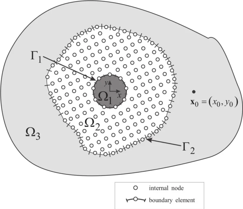
Figure 1:Problem definition.
3.1 MLPG formulation for domain Ω2
The MLPG technique[Atluri(2004)]was chosen for the meshless analysis of elastic wave propagation in the domain Ω2,assuming the MLS approximation for the definition of the trial functions and Heaviside unit step function as a test function in each local subdomain ΩS.Instead of writing the global weak form,the MLPG is based on the local weak form of the governing equations.The shape of the local integration domain ΩScan be arbitrary,and we adopted the cylindrical shape aligned in the longitudinal z=3 direction.Since the problem is assumed infinite in the longitudinal direction,the volume integral can be decomposed as an integral over the z-coordinate and the cross section of cylinder ΩS.The local integration domain ΩSis shown in Fig.2 for the 2D example.
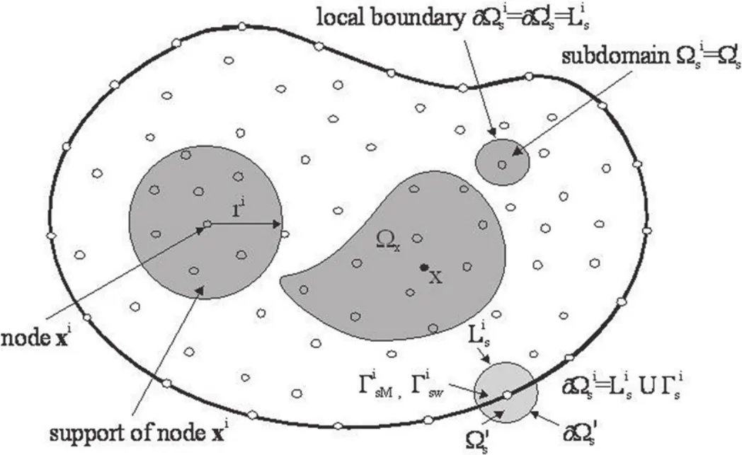
Figure 2:Local boundaries for the weak formulation,the domain Ωx for MLS approximation of the trial function,and the support area of weight function around a node.
The local weak form of Eq.(9)is then written over each subdomain ΩSas

Applying the Gauss divergence theorem to the left-hand side integral in Eq.(12)leads to

where nj(x)is the unit normal vector and∂ΩSis the boundary of the subdomainΩS.Assuming the Heaviside unit step function for the test function

the following local integral equation(LIE)is finally obtained


The Fourier transform of the stress tensor σijin the axial z-direction can be expressed in terms of the Fourier transforms of displacements for α,β,γ=1,2 as

Thus,LIE(15)for i=β takes the form

while for i=3 we obtain


For the approximation of derivatives of displacements(strains),we can use

The number of nodes N used for the approximation is determined by the weight function wi(x).A 4thorder spline-type weight function is applied in the present work as follows,

Discretized LIEs are obtained by substitution of expressions(20)and(21)for spatial MLS approximants of displacements and their derivatives into Eqs.(18)and(19)considered for each subdomain Ωcs⊂Ω2as
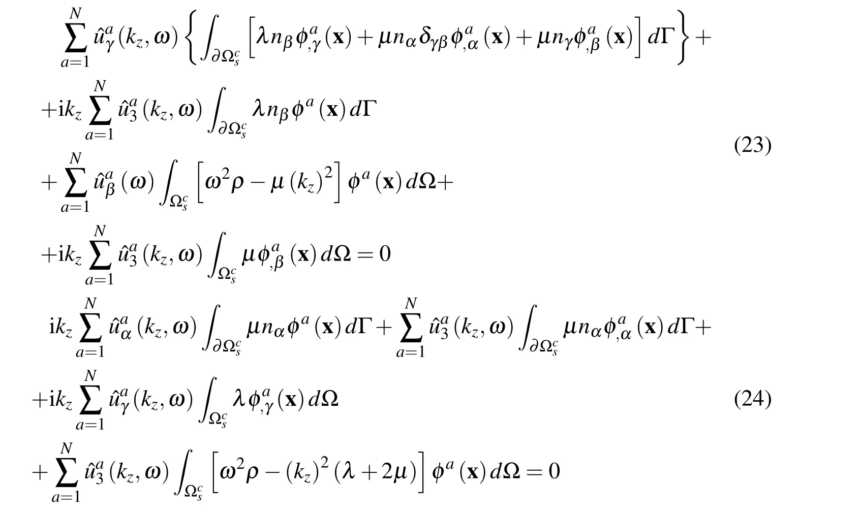
Eqs.(23,24)are applied to all interior nodes xc,(c=1,2,...,Nin)located inside the domain Ω2and surrounded by the subdomain Ωcs⊂ Ω2,leading to 3Ninequations.The BEM approach is used for the nodes on the boundary.Boundary elements with one node in the centre of the element are used.These nodes are also used for the MLS approximations(20),(21).
3.2 BEM formulation for domain Ω3
The BEM solution of Eq.(2)for 2.5-D problem in medium Ω3,bounded by surface Γ2and subjected to an incident displacement field uinciis presented next.By applying the reciprocity theorem we obtain the following boundary integral equations:


3.3 BEM formulation for domain Ω1


where Hn(...)are second kind Hankel functions of the order n and

is assumed with Im(kcp1)<0.
The boundary Γ1is then discretized into N1beconstant boundary elements,with each having one nodal point.The necessary integrations over the boundary elements can generally be performed by means of standard Gaussian quadrature.To ensure that the method is accurate,when the loaded element coincides with the integrated element the resulting singular integration should be performed analytically,following,for example,the expressions in[Tadeu,Santos and Kausel(1999a,b)].
3.4 Coupled BEM-MLPG formulation for interface Γ2
This section describes how the mutual coupling of the BEM and the MLPG is formulated to obtain the elastic wave field generated by a dynamic load.This approach exploits a direct coupling between the BEM and MLPG.It can be done when the nodes used by the BEM match the nodes used by the MLPG.If the boundary nodes coincide,then the continuity of displacements and the equilibrium of tractions can be imposed directly.


which should be valid at any point on the interface Γ2= ∂Ω3.The association of boundary densities to domains Ω2and Ω3is denoted by the left superscripts 2 and 3,respecively.The problem in the domain Ω2is described using the MLPG,while in the domain Ω3it is simulated using the BEM.
The displacement and traction fields at the interface Γ2can be approximated using the MLS approximations(20)and(21).The tractions are then given as

where the unit normal vector n(x)at x∈Γ2is considered as outward from the point of view of the domain Ω3.
The mutual direct coupling between the BEM and the MLPG is accomplished by inserting the coupling conditions(29)into the boundary integral equation(25),which leads to

Finally,the numerical solution of Eq.(32)involves discretizing the boundary Γ2into a set of N2beboundary elements Γqwith constant approximation of boundary densities,leading to


3.5 Coupled BEM-MLPG formulation for interface Γ1
At any point x on the interface Γ1=∂Ω1we must impose four boundary conditions between the solid and fluid:continuity of normal stresses and displacements and null shear stress.


4 Verification of the proposed numerical procedure
The accuracy of the proposed model is verified by taking a non-homogeneous elastic annular circular fluid filled borehole region Ω2,with an internal radius rint=0.75 m and an external radius rext=1.50 m,centered at(xcen=0.0 m;ycen=0.0 m)and buried in an unbounded homogeneous elastic medium Ω3.The fluid filled domain is denoted as Ω1.The system is excited by a blast line load whose amplitude varies sinusoidally in the third dimension(kz=0.8 rad/m),located at a given point(x0=−4.0 m;y0=0.0 m)in the outer homogeneous domain,as illustrated in Figure 3.
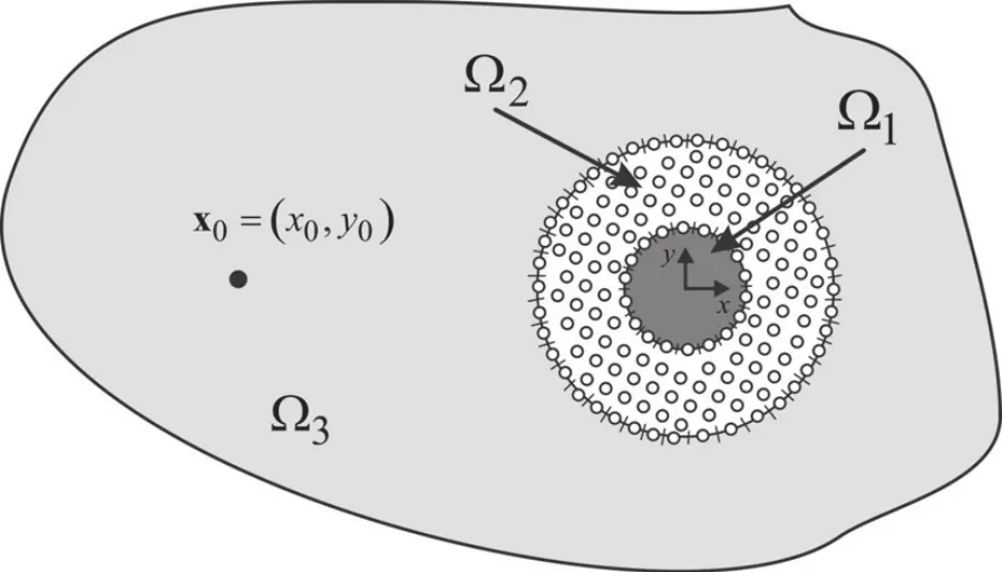
Figure 3:Geometry of the model used to verify the algorithm.
The host medium,with an elasticity modulus of E0=11689288.6 kPa,a Poisson ratio of 0.29593 and density of 2140 kg/m3,allows P and S wave velocities of 2696.5 m/s and 1451.7 m/s,respectively.Inside the non-homogeneous circular annular region the density of 2500 kg/m3and the Poisson ratio of 0.15 are assumed to be constant.However,a radial variation of the elasticity modulus is assumed as follows,


4.1 Evaluation of accuracy of the proposed model
Several simulations were performed to verify the proposed model.The results for a harmonic source with a frequency of 1000.0 Hz are presented next,to illustrate the accuracy of the solutions.In the next figures the analytical responses and the numerical error are displayed for the displacements(in the x,y and z directions)and for the pressure.Displacements and pressures were computed over a grid of 7953 receivers(Nrecsol=7342 in the solid media and Nrecfl=611 in the fluid medium),spaced at equal intervals in the two orthogonal directions and placed between(x=−2.25 m;y=−2.25 m)and(x=2.25 m;y=2.25 m).

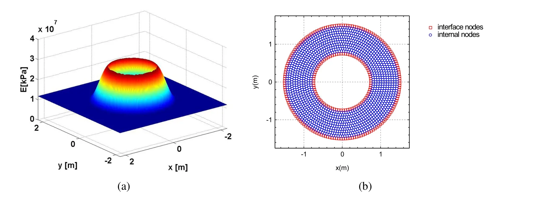
Figure 4:Verification and accuracy for a source excitation frequency of 1000.0 Hz:a)elasticity modulus variation;b)node distribution.
The variation pattern of the elastic modulus is presented in Figure 4a,while the distribution of the 180 boundary nodes on Γ2and the 90 boundary nodes on Γ1,together with 1755 internal nodes used to compute the solution,is displayed in Figure 4b.A regular distribution of nodal points has been adopted since it best suits the character of the problem.Regular node distribution is also most appropriate for specifying both the local subdomains and the support domains.Non-uniform nodal distribution can also be used,although one must ensure that a sufficient number of nodes will be used for accuracy of the local approximation to remain high.
Figures 5 to 8 present the results obtained for the displacements in three directions(x,y and z)and for the pressure.Each Figure contains plots showing the real and imaginary parts of the analytical solution and the numerical error.The results show a good agreement between the two solutions.
4.2 Evaluation of the averaged error of the proposed model
The number of the nodal points and the radius of the circular support domain both influence the accuracy of the response.The effect of those two parameters on the response error has therefore been assessed.Computations were performed using a geometry similar to that described above,over the same grid of receivers.For the external interface Γ2we have considered 80 to 180 boundary nodes,for the internal boundary on the interface Γ1we have considered 40 to 90 boundary nodes,together with 300 to 1755 regularly distributed internal nodes.The number of the internal nodes was defined so that the distance between them was the same as that between the boundary nodes.The error for each receiver is calculated as the difference between the analytical and the numerical result.The global performance of the solution is assessed by the normalized average error,computed in the solid media
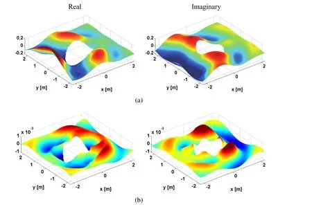
Figure 5:Verification and accuracy for a source excitation frequency of 1000.0 Hz:a)Analytical displacement in x direction;b)Numerical error when ri=3h.
and fluid medium as follows,

where ui(x,kz,ω)and p(x,kz,ω)are the analytical displacements and pressure solutions;|ui,max(x,kz,ω)|and|pmax(x,kz,ω)|are the maximum absolute response over the grid of receivers;ˆui(x,kz,ω)andˆp(x,kz,ω)are the numerical results.
The radius of the circular support domain changes from rs=0.1 m to rs=1.0 m in increments of0.01 m.Four frequencies were analyzed,namely,500.0 Hz,1000.0 Hz,2000.0 Hz,and 4000.0 Hz.Figures 9 to 12 illustrate how the error varies with the ratio between the radius of the circular support domain and the distance between nodal points(ri/h)and the number of boundary elements at the interface Γ2.The amplitude average error is presented on a logarithmic scale to enhance the errors.In the case where the radius of the circular support domain is not large enough to cover a sufficient number of nodes in the defined domain to ensure the regularity of the MLS shape function,the responses are not computed.
Analysis of the results showed that the error was higher at higher frequencies.For those frequencies,the best results are found for high values of boundary elements and for relatively low values of ri/h.A good value of the relation ri/h is close to 3.The accuracy is expected to improve if the number of boundary elements were increased further.At lower frequencies the average error was very low,of the order of 1×10⁻⁸.
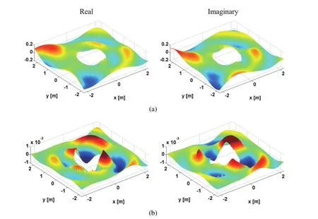
Figure 6:Verification and accuracy for a source excitation frequency of 1000.0 Hz:a)Analytical displacement in y direction;b)Numerical error when ri=3h.
5 Numerical example
The algorithm developed was applied to a problem where two circular annular fluid borehole regions,both with internal radius(rint=0.75 m)and external radius(rext=1.50 m)and filled with water,are buried in an infinite elastic medium,as shown in Figure 13.The unbounded solid and fluid are assumed to have the properties described above.In one example,a smooth increasing change in the elastic modulus occurs towards the centre,whereas in the second example the elastic modulus suffers a smooth decrease(see Figure 14).The borehole inclusions are centred at(x=0.0 m;y=0.0 m)and(x=0.0 m;y=3.5 m).The medium is excited by a blast line load with kz=0.8 rad/m placed at(x0=−5.0 m;y0=1.75 m).The circular support domain used in the computations was set at 3 times the nodal point distance.
In the first example(Case 1),the change in the elasticity modulus within the annular circular non-homogeneous region of each fluid-filled borehole follows equation(38)(see Figure 14a),assuming the density and the Poisson ratio values already adopted for the example with a single inclusion.

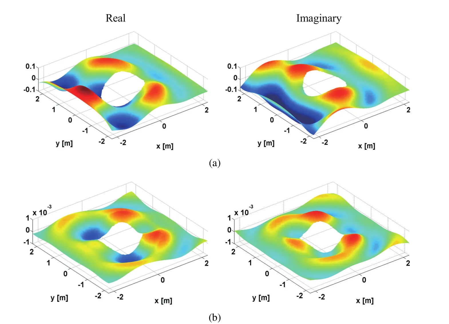
Figure 7:Verification and accuracy for a source excitation frequency of 1000.0 Hz:a)Analytical displacement in z direction;b)Numerical error when ri=3h.
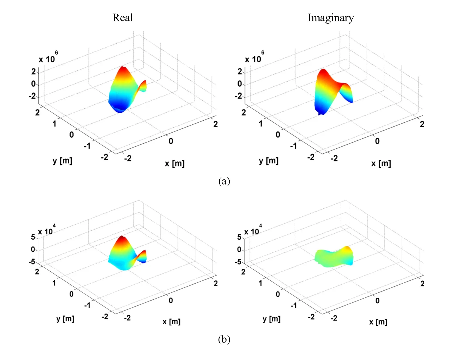
Figure 8:Verification and accuracy for a source excitation frequency of1000.0 Hz:a)Analytical pressure;b)Numerical error when ri=3h.
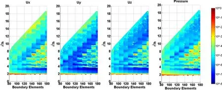
Figure 9:Average normalized error of the numerical solution showing the relation between the radius of the circular support domain and the distance between nodal points for a frequency of 500 Hz.
In the second example(Case 2),the elasticity modulus within the annular circular non-homogeneous region of each fluid-filled borehole varies according to withE1=2591860.0 kPa while the density of 2140 kg/m3and a Poisson ratio of 0.29593 are kept constant(see Figure 14b).The velocities for the P-wave and S-wave velocities in the vicinity of the fluid-filled borehole wall are 1269.7 m/s and 683.6 m/s,respectively.
Computations in the frequency range of[30,7680.0 Hz]with a frequency increment of 30.0 Hz were performed over a fine grid of 13630 receivers placed between(x=−4.5 m;y=−2.75 m)and(x=4.5 m;y=6.25 m)forz=0.0 m to obtain displacements and pressures.Each annular region was discretized using 160 exter-nal boundary elements and 80 internal boundary elements and 1320 internal nodal points.The internal nodal points were arranged evenly throughout each annular circular non-homogeneous region.
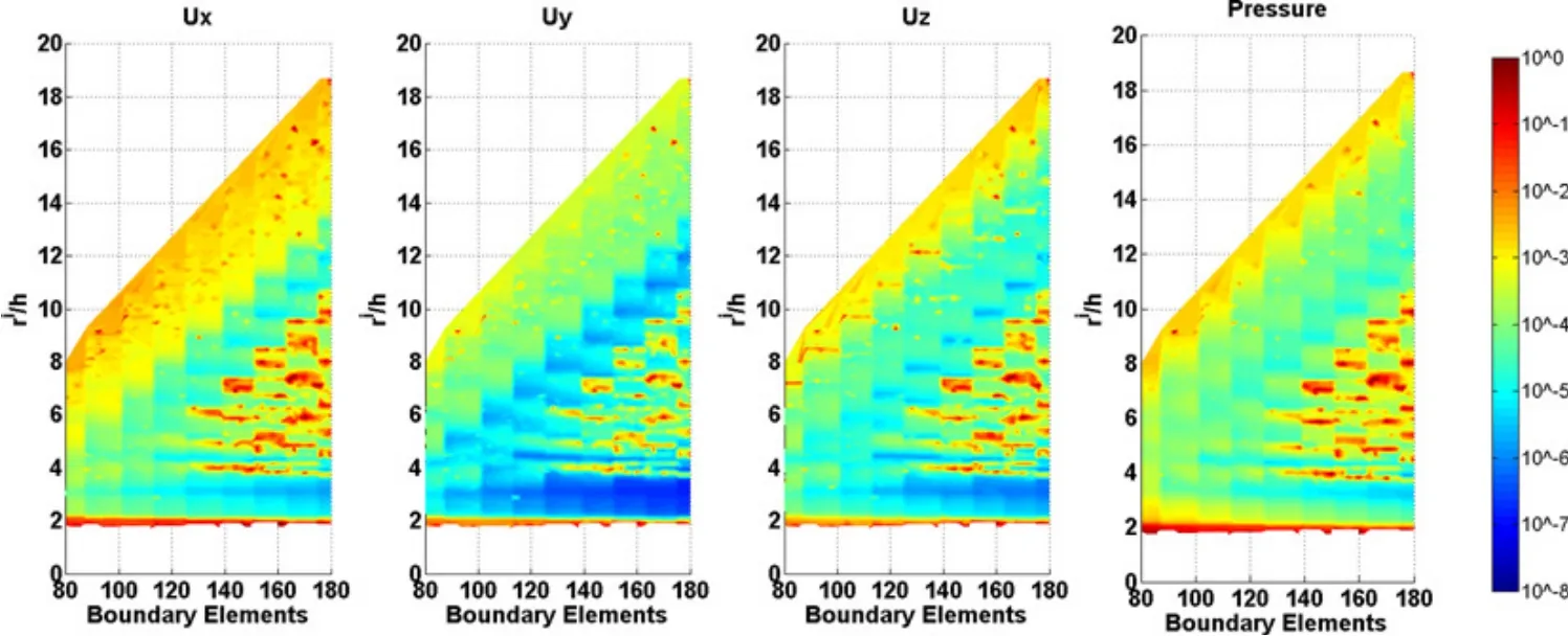
Figure 10:Average normalized error of the numerical solution showing the relation between the radius of the circular support domain and the distance between nodal points for a frequency of 1 000 Hz.
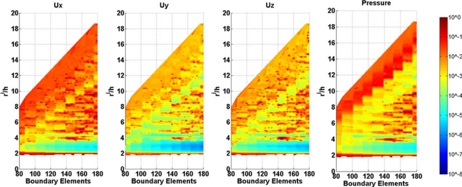
Figure 11:Average normalized error of the numerical solution showing the relation between the radius of the circular support domain and the distance between nodal points for a frequency of 2 000 Hz.
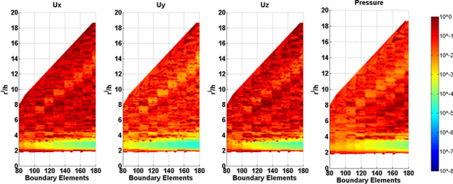
Figure 12:Average normalized error of the numerical solution showing the relation between the radius of the circular support domain and the distance between nodal points for a frequency of 4 000 Hz.
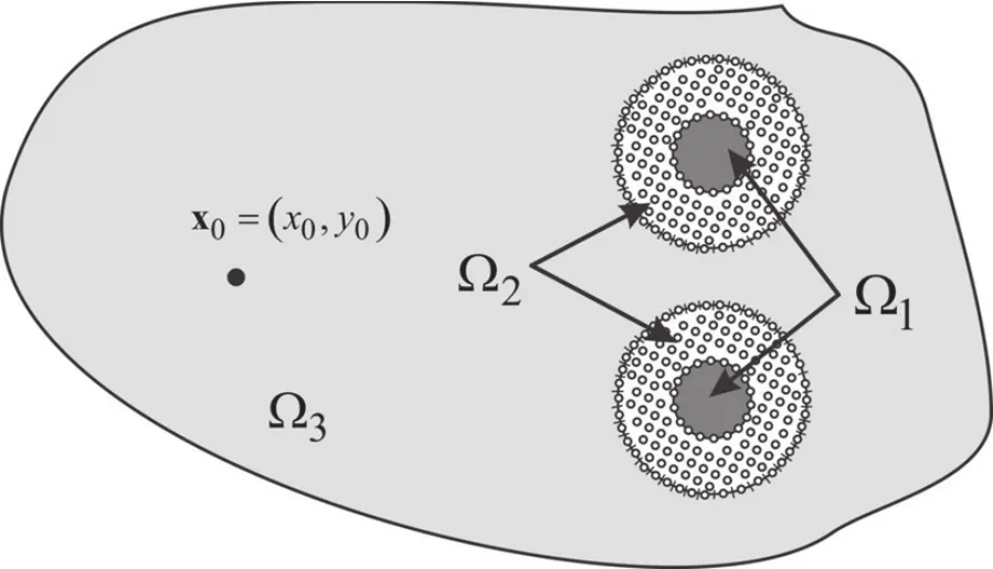
Figure 13:Geometry used in the numerical applications.

Figure 14:Elastic modulus in the vicinity of the fluid-filled borehole:a)Smooth increasing change(Case 1);b)Smooth descreasing change(Case 2).
An inverse Fourier transformation was applied to the frequency results to obtain time responses.The source was assumed to have a temporal variation similar to a Ricker pulse with a characteristic frequency of 2500 Hz.The Ricker pulse may be defined in the frequency domain as
where A is the amplitude,Ω=ω to/2,tsis the time when the maximum occurs,while πtois the characteristic period of the wavelet.This procedure defines a total time window of T=2π/Δω (where Δω is the frequency step)for the time domain analysis.A Ricker pulse was simulated because it decays rapidly in the frequency domain and is of short duration,which meant the computations could be limited to a narrow frequency range and offered an easy interpretation of the time signals.
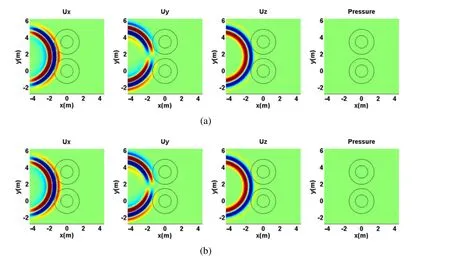
Figure 15:Time domain displacements in the x,y and z directions at t=1.3 ms:a)Case 1;b)Case 2.
Aliasing phenomena were avoided by using complex frequencies with a small imaginary part of the form ωc= ω −iη (with η =0.7Δω).This attenuation,introduced in the frequency domain,was removed by rescaling the response in the time domain using an exponential window,eηt.
Figures 15 to 17 give time domain plots showing the displacements(in the x,y and z directions)and pressure at different time instants(t=1.5 ms,t=2.0 ms,t=2.5 ms and t=3.2 ms).Two plots are presented in each figure,corresponding to the two cases under simulation,at each time instant.A color scale is used in which the red shades represent positive and the blue shades negative displacement values.
In Figure 15(a)and(b),for t=1.3ms,the incident field has already entered the annular region of the borehole.At this instant,the interference due to the difference of velocities between the annular region and the infinite media in the wave propagation is very slight.
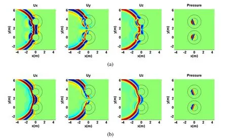
Figure 16:Time domain displacements in the x,y and z directions at t=1.9 ms:a)Case 1;b)Case 2.
At t=1.9 ms,Figure 16 shows that the wavefront has already arrived inside the fluid- filled borehole and backward reflections outside the annular region are visible.At this instant,the distortion of the wave inside the annular region due to the smooth change of velocity(refraction)and to the diffraction around the fluid- filled hole can be seen.Additionally,in Figure 16(a)it can be seen that the velocity is higher inside the annular region than in the in finite medium,due to the increase in the elastic modulus,while in Figure 16(b)the decrease in the elastic modulus leads to lower propagation pulse velocities inside the annular region.The first changes in fluid pressure are also visible.
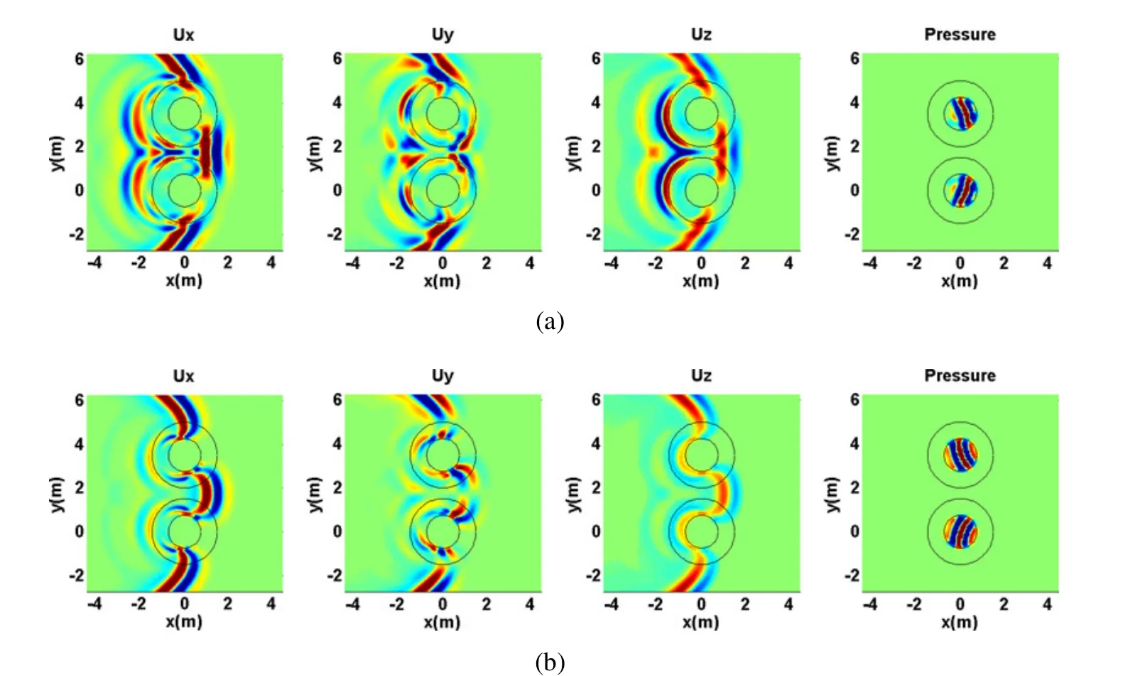
Figure 17:Time domain displacements in the x,y and z directions at t=2.4 ms:a)Case 1;b)Case 2.
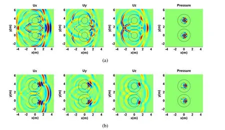
Figure 18:Time domain displacements in the x,y and z directions at t=3.2 ms:a)Case 1;b)Case 2.
Figure 17 shows the response at t=2.4 ms.Now,we can see the effect of multiple reflections inside the fluid-filled borehole.The distortion and the delay or advance of the wavefront is very noticeable because of the change in the elastic modulus.It can be seen that the backward reflections are strong when the elastic modulus increases(Figure 17 a),whereas they are weaker when the elastic modulus decreases(Figure 17b).
The wave propagation proceeds and at time t=3.2 ms a more complex wave field can be seen,caused by the reflections,multiple reflections,refraction and diffraction of waves.
6 Conclusion
This paper has presented a coupled numerical model using the meshless local Petrov-Galerkin (MLPG) method and the boundary element method (BEM) for the simulation of transient solid-fluid wave propagation, in the frequency domain,of homogenous unbounded media containing a non-homogeneous elastic annular circular fluid-filled borehole region with medium properties that changes smoothly in the annular regions. The BEM was used to simulate the wave propagation in the outer medium and the inner fluid-filled domain, while the MLPG was used to model the localized regions with non-homogeneous properties, for which the BEM is not suitable. In the MLPG method, the governing partial differential equations were satisfied in a weak-form for small fictitious subdomains. A unit step function was used as the test function in the local weak-form of the governing partial differential equations for small circular subdomains, spread around the analyzed domain. The moving least-squares (MLS) scheme was used to approximate the field quantities.The accuracy of the proposed model was corroborated for different frequencies against an analytical solution developed for a circular fluid-filled borehole bounded by a confined circular annular subdomain, in which the elastic properties (Young’s modulus) vary in the radial direction. It was demonstrated that the accuracy of the results obtained with the proposed model varies with the radius of the support domain and the number of nodal points. The calculation of the average error for different relations between the radius of the circular support domain and the distance
The applicability of the proposed model was illustrated by modeling two circular annular inclusions with variable elastic material properties.The temporal pattern of the pressure and displacement wave field observed in the plots was found to be consistent with the physics of the problem.
Acknowledgement:The support of the Slovak Science and Technology Assistance Agency registered under the project number APVV-14-0440 is gratefully acknowledged.
Appendix A:2.5D Cylindrical fluid-elastic multilayered analytical solution
This Appendix defines the basic equations to compute the reference analytical solution used for benchmarking the proposed numerical model.For this purpose we consider a system built from a set ofmtwo-dimensional circular,concentric elastic layers,bounded by an infinite elastic medium,mediumm+1(see Figure A1).The inner medium,labeled medium 0,is fluid,with mass densityρ0,allowing pressure wave velocitiescp0.The material properties and thickness of the various elasticmlayers and of the unbounded medium may differ(mass densityρj,shear wave velocitiescsjand dilatational wave velocitiescpj).This system is subjected to a blast harmonic line source,whose amplitude varies sinusoidally in the third z-dimension,placed somewhere in the domain at point O of coordinates(x0,y0).
In a cylindrical coordinate system,the wave propagation in each elastic layer,governed by Eq.(9),can be expressed as a function of a dilatational potential(φ)and two shear scalar potentials(ψ,χ),while the pressure wave propagation in the inner fluid medium,governed by Eq.(11),can be computed as a function of a dilatational potential(φ).Each potential satis fies a wave equation,which reduces to the Helmholtz equation in the frequency domain.The solution for this problem can be defined by applying the separation of variables procedure to the Helmholtz equation in each medium of the system and enforcing the boundary conditions at all interfaces,using a series of Bessel functions.
A.1Incident field
If there is a source in the elastic layerj,at pointx0with coordinates(x0,y0),the incident field pointxwith coordinates(x,y)can be expressed as

Eq.(A1)expresses the incident field as wave terms centered at the source point and not at the axis of the concentric multilayer system.However,this can be achieved by applying Graf’s addition theorem[Watson(1980)],which results in the expressions below(in cylindrical coordinates):

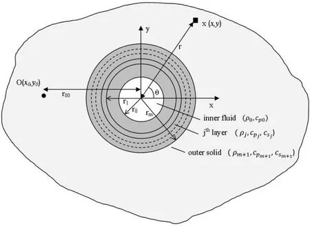
Figure A1:Geometry of the problem for the reference solution,with a circular,concentric,fluid-elastic multilayer system bounded by an infinite elastic medium(medium m+1).

in whichεn=1 ifn=0,εn=2 ifn>0,r00is the distance from the source to the axis of the multilayer system,ris the distance from pointxto the center of the multilayer system at(0,0)(see Figure A1).
A.2The scattered and refracted field within each elastic cylindrical layer
The total displacement field is found by adding the incident field to the sets of scattered and refracted terms arising within each layer and at each interface.For the layerj(j/=0),the scattered and refracted terms on the inner and outer interfaces can be expressed as


whereAtnj,Abnj,Btnj,Bbnj,CtnjandCbnjare unknown amplitudes.
A.3The scattered field within the fluid
The pressure field is defined by computing the scattered field arising within the fluid inner and at interface 1,

A.4System of equations
A system of 6m+4 equations is derived,ensuring the following boundary conditions:
-continuity of displacements and tractions between layers at theminterfaces between elastic layers;
-continuity of normal displacements,continuity of normal tractions and null shear stress at the fluid-elastic interface.
Each equation takes into account the contribution of the scattered and refracted field and the involvement of the incident field.
The resolution of the system gives the amplitude of the scattered and refracted terms at each interface.The displacement field for each elastic layer is found by adding these terms to the contribution of the incident field,while the pressure field is computed by adding the contribution of the pressure field terms within the fluid.
Albright,J.N.;Johnson,P.A.(1990):Cross-borehole observation of mode conversion from borehole Stoneley waves to channel waves at a coal layer.Geophysical Prospecting,vol.38,pp.607–620.
Antonio,J.;Tadeu,A.(2002):3D seismic response of a limited valley via BEM using 2.5D analytical Green’s functions for an infinite free-rigid layer.Soil Dynamics and Earthquake Engineering,vol.22,pp.659–673.
Antonio,J.;Tadeu,A.(2004):The use of monopole and dipole sources in cross well surveying.Journal of Applied Geophysics,vol.56,pp.231–245.
Atluri,S.N.(2004):The meshless local petrov-galerkin(MLPG)method.Tech.Science Press.
Atluri,S.N.;Sladek,J.;Sladek,V.;Zhu,T.(2000):The local boundary integral equation(LBIE)and its meshless implementation for linear elasticity.Computational Mechanics,vol.25,pp.180–198.
Ávila-Carrera,R.;Sánchez-Sesma,F.J.;Spurlin,J.H.;Valle-Molina,C.;Rodríuez-Castellanos,A.(2014):Analytic simulation of the elastic waves propagation in the neighborhood of fluid filled wells with monopole sources.Pure and Applied Geophysics,vol.171,no.9,pp.2209–2223.
Baker,L.J.(1984): The effect of the invaded zone on full wavetrain acoustic logging.Geophysics,vol.49,pp.796–809.
Baker,L.J.;Winbow,G.A.(1988):Multipole P-wave logging in formations altered by drilling.Geophysics,vol.53,pp.1207–1218.
Bell,J.S.;Gough,D.I.(1979): Northeast–southwest compressive stress in Alberta—evidence from oil wells,Earth planet.Sci.Lett.,vol.45,pp.475–482.
Biot,M.A.(1952):Propagation of elasticwaves in cylindrical bore containing a fluid.J.Appl.Phys.,vol.23,pp.997–1005.
Blair,D.P.(1984):Rise times of attenuated seismic pulses detected in both empty and fluid- filled cylindrical boreholes.Geophysics,vol.49,pp.398–410.
Bouchon,M.(1993):A numerical simulation of the acoustic and elastic wave-fields radiated by a source in a fluid- filled borehole embedded in a layered medium.Geophysics,vol.58,pp.475–481.
Bouchon,M.;Aki,K.(1977):Discrete wave-number representation of seismic-source wave fields.Bulletin of the Seismological Society of America,vol.67,pp.259–277.
Bouchon,M.;Schmitt,D.P.(1989):Full wave acoustic logging in an irregular borehole.Geophysics,vol.54,pp.758–765.
Castro,I.;Tadeu,A.(2012):Coupling of the BEM with the MFS for the numerical simulation of frequency domain 2-D elastic wave propagation in the presence of elastic inclusions and cracks.Engineering Analysis with Boundary Elements,vol.36,pp.169–180.
Chen,T.;Raju,I.S.(2003):A coupled finite element and meshless local Petrov-Galerkin method for two-dimensional potential problems.Computer Methods in Applied Mechanics and Engineering,vol.192,pp.4533–4550.
Cheng,N.;Cheng,C.H.;Toksoz,M.N.(1995):Borehole wave propagation in three dimensions.Journal of the Acoustical Society of America,vol.97,pp.3483–3493.
De Hoop,A.T.;De Hon,B.P.;Kurkjian,A.L.(1994):Calculation of transient tube wave signals in cross-borehole acoustics.Journal of the Acoustical Society of America,vol.95,pp.1773–1789.
Dong,L.;Atluri,S.N.(2012):Development of 3D trefftz voronoi cells with ellipsoidal voids&/or elastic/rigid inclusions for micromechanical modeling of heterogeneous materials.CMC:Computers Materials and Continua,vol.30,no.1,pp.39–82.
Dong,L.;Atluri,S.N.(2013):SGBEM Voronoi Cells(SVCs),with embedded arbitrary-shaped inclusions,voids,and/or cracks,for micromechanical modeling of heterogeneous materials.CMC:Computers,Materials&Continua,vol.33,no.2,pp.111–154.
Dong,L.;Alotaibi,A.;Mohiuddine,S.A.;Atluri,S.N.(2014):Computational methods in engineering:a variety of primal&mixed methods,with global&local interpolations,forwell-posed or Ill-posed BCsCMES:Computer Modeling in Engineering&Sciences,vol.99,no.1,pp.1–84.
Dong,W.;Bouchon,M.;Toksfz,M.N.(1995): Borehole seismic source radiation in layered isotropic and anisotropic media:boundary element modeling.Geophysics,vol.60,pp.735–747.
François,S.;Schevenels,M.;Galvín,P.;Lombaert G.;Degrande,G.(2010):A 2.5D coupled FE–BE methodology for the dynamic interaction between longitudinally invariant structures and a layered halfspace.Comput.Methods Appl.Mech.Engrg,vol.199,pp.1536–1548.
Gibson,R.L.Jr.;Peng,C.(1994): Low-and high-frequency radiation from seismic sources in cased boreholes.Geophysics,vol.59,pp.1780–1785.
Godinho,L.;Tadeu,A.(2012): Acoustic analysis of heterogeneous domains coupling the BEM with Kansa’s method.Engineering Analysis with Boundary Elements,vol.36,pp.1014–1026.
Godinho,L.;Tadeu,A.;Simões,N.(2006):Accuracy of the MFS and BEM on the analysis of acoustic wave propagation and heat conduction problems.In:Advances in Meshless Methods,Jan Sladek,Vladimir Sladek(eds).Tech Science Press.
Gu,Y.T.;Liu,G.R.(2005):Meshless methods coupled with other numerical methods.Tsinghua Science&Technology,vol.10,pp.8–10.
Kausel,E.(1992):Frequency domain analysis of undamped systems.Journal of Engineering Mechanics,ASCE,vol.118,pp.721–734.
Krohn,C.E.(1992):Crosswell continuity logging using guided seismic waves.The Leading Edge,vol.11,pp.39–45.
Leslie,H.D.;Randall,C.T.(1992):Multipole sources in boreholes penetrating anisotropic formations:numerical and experimental results.Journal of the Acoustical Society of America,vol.91,pp.12–27.
Liu,G.R.;Gu,Y.T.(2000):Meshless local Petrov-Galerkin(MLPG)method in combination with finite element and boundary element approaches.Computational Mechanics,vol.26,pp.536–546.
Randall,C.T.(1991):Multipole acoustic waveforms in nonaxisymmetric boreholes and formations.Journal of the Acoustical Society of America,vol.90,pp.1620–1631.
Schmitt,D.P.;Bouchon,M.(1985): Full-wave acoustic logging:synthetic microseismograms and frequency–wavenumber analysis,Geophysics,vol.50,pp.1756–1778.
Sladek,J.;Sladek,V.;Zhang,Ch.(2003):Application of meshless local Petrov–Galerkin(MLPG)method to elastodynamic problems in continuously nonhomoge-neous solids.CMES:Computer Modeling in Engineering and Sciences,vol.4,pp.637–648.
Sladek,J.;Stanak,P.;Han,Z.D.;Sladek,V.;Atluri,S.N.(2013):Applications of the MLPG method in engineering&sciences:a review.CMES:Computer Modeling in Engineering&Sciences,vol.92,no.5,pp.423–475.
Soares,D.Jr.(2009): An iterative time-domain algorithm for acoustic-elastodynamic coupled analysis considering meshless local Petrov-Galerkin formulations.CMES:Computer Modeling in Engineering&Sciences,vol.54,no.2,pp.201–222.
Stephen,R.A.;Cardo-Casas,F.;Cheng,C.H.(1985):Finite difference synthetic acoustic logs.Geophysics,vol.50,pp.1588–1609.
Tadeu,A.;Antonio,J.(2001):2.5D Green’s functions for elastodynamic problems in layered acoustic and elastic formations.CMES-Computer Modeling in Engineering and Sciences,vol.2,no.4,pp.477–495.
Tadeu,A.;Godinho,L.;Santos,P.(2002):Wave motion between two fluid filled boreholes in an elastic medium.Engineering Analysis with Boundary Elements,vol.26,pp.101–117.
Tadeu,A.;Kausel,E.(2000):Green’s functions for two-and-a-half dimensional elastodynamic problems.Journal of Engineering Mechanics,ASCE,vol.126,pp.1093–1097.
Tadeu,A.;Santos,P.F.A.;Kausel,E.(1999a): Closed-form integration of singular terms for constant,linear and quadratic boundary elements:Part I.SH wave propagation.EngineeringAnalysiswithBoundaryElements,vol.23,pp.671–681.
Tadeu,A.;Santos,P.F.A.;Kausel,E.(1999b): Closed-form integration of singular terms for constant,linear and quadratic boundary elements:Part II.SVP wave propagation.Engineering Analysis with Boundary Elements,vol.23,pp.757–768.
Tadeu,A.;Simões,N.;Simões,I.(2010):Coupling BEM/TBEM and MFS for the simulation of transient conduction heat transfer.Int J Numer Methods Eng,vol.84,no.2,pp.179–213.
Tadeu,A.;Stanak,P.;Antonio,J.;Sladek,J.;Sladek,V.(2015):2.5D Elastic wave propagation in non-homogeneous media coupling the BEM and MLPG methods.Engineering Analysis with Boundary Elements,vol.53,pp.86–99.
Tadeu,A.;Stanak,P.;Sladek,J.;Sladek,V.(2014):Coupled BEM–MLPG acoustic analysis for non-homogeneous media,Engineering Analysis with Boundary Elements,vol.44,pp.161–169.
Tadeu,A.;Stanak,P.;Sladek,J.;Sladek,V.;Prata,J.;Simões,N.A.(2013):Coupled BEM-MLPG technique for the thermal analysis of non-homogeneous media.CMES-Computer Modeling in Engineering&Sciences,vol.93,no.6,pp.489–516.
Watson,G.N.(1980):A treatise on the theory of Bessel functions.Cambridge University Press,second edition.
Wen,P.H.;Aliabadi,M.H.(2008):An improved meshless collocation method for elastostatic and elastodynamic problems.Commun Num Meth Eng,vol.24,pp.635–651.
White,J.E.;Sengbush,R.L.(1963): Shear waves from explosive sources.Geophysics,vol.28,pp.1001–1019.
Zhao,M.;Nie,Y.(2008):A study of boundary conditions in the meshless local Petrov-Galerkin(MLPG)method for electromagnetic field computations.CMES:Computer Modeling in Engineering&Sciences,vol.37,no.2,pp.97–112.
Zheng,Z.;Kemeny,K.;Cook,N.G.W.(1989):Analysis of borehole breakouts.J.geophys.Res.,vol.94,pp.171–182.
1ITeCons,University of Coimbra,Pólo II,Rua Pedro Hispano,3030-289,Coimbra,Portugal
2Institute of Construction and Architecture,Slovak Academy of Sciences,84503 Bratislava,Slovakia technique.

