
Orthogonal Stacked Spectral Coding Labels for Fast Packets Routing over Optical MPLS Network
2015-11-18 10:11:39KaiShengChenChaoChinYangandJenFaHuang
Kai-Sheng Chen, Chao-Chin Yang, and Jen-Fa Huang
Orthogonal Stacked Spectral Coding Labels for Fast Packets Routing over Optical MPLS Network
Kai-Sheng Chen, Chao-Chin Yang, and Jen-Fa Huang
—Multi-protocol label switching (MPLS)has the advantage of high efficiency in the second layer,which improves the performance of data packets routing. In this paper, a new structure to implement optical MPLS is proposed. We construct a code family for spectral-amplitude coding (SAC) labels in the optical MPLS networks. SAC labels are suitable for optical packet switching because they can be constructed and recognized quickly at each router. We use the label stacking to provide hierarchical routing to avoid swapping labels at each forwarding node and reduce system complexity. However, the phase-induced intensity noise (PIIN) appears due to the incoherent property of the light source when the stacked labels set makes the correlation decoding with the local node label,which degrades system performance.
Index Terms—Arrayed waveguide grating, Internet protocol, label-switching path, multi-protocol label switching, spectral amplitude coding.
1. Introduction
Nowadays, Internet protocol (IP) is the general protocol to transfer data and multimedia[1]. With the rapid increasing of information, to provide large number of clients searching for high-quality applications, the evolvement of Internet with faster information transportation is needed. In classical IP networks, each router determines the next hop by executing routing algorithms individually when transmitting packets. When a packet is transmitted in a network, each router analyzes its header to get the IP address of destination, and then looks up the routing table to forward. And routers should repeat the same procedure in each forward even though having the same destination. The processing time will certainly increase since it requires doing IP routing for each forward in each router.
Multi-protocol label switching (MPLS)[2]was proposed for a packet routed according to its label at the forwarding node. Great processing delay can be shortened at each node since the label de-composition in the network layer is averted. In another word, MPLS simplifies the forwarding function of routers. Without abandoning the basic of IP network, MPLS is considered as an extension protocol. MPLS provides a more flexible, extensible, and more efficient packet switching technique. Nevertheless, the electrical routing architecture still has a challenge when the IP services expand with the data traffic. Resent years, more interest focuses on developing optical packet switched networks to overcome the bottlenecks in transport and access networks[3]. By constructing all-optical node, optical packet switching (OPS) is a good solution since it simplifies several layers exiting in the present protocol stack into two. In optical MPLS, packets are transmitted node by node according to their label switching paths(LSPs). Their paths are determined by edge nodes at first,but requiring adding appropriate labels to the packets.
Optical orthogonal labels coding, inspired by optical code-division multiple-access (OCDMA), is one of the promising approaches for implementing optical labels. These labels have shorter length, hence the complexity of the optical nodes is reduced. In this paper, we use spectral amplitude coding (SAC) as optical labels because they can be constructed easily and have low system cost[4],[5]. Each node is assigned a particular code as a label. Labels are encoded only at the source end. These labels can bypass the main bottleneck of electrical routers, i.e., lookup tables, and achieve all optical recognition by a balanced detector. In forwarding nodes, the incoming label is decoded over the balanced detector to detect a match. If the label and the decoder are matched, the auto correlation property would produce a control signal to route the packet into the proper path.
In this paper, we propose a new structure to implement optical MPLS. The major techniques in this structure include an arbitrary waveform generator (AWG)[6], the label stacking, and the label recognition. The labels are added at the ingress and removed at the egress. Both the ingress and egress are the marginal nodes of MPLS networks. The label generator uses the label stackingachieved by AWG. In the MPLS network, each node performs the label recognition. As we use an incoherent broadband light source (BLS) as the method from SAC-labels encoding, the phase-induced intensity-noise(PIIN) seriously produces a change in system performance because the BLS changes frequently in intensity. So we have to analyze the PIIN effect on systems.
The rest of this paper is organized as follows. In Section 2, we explain the label stacking and SAC labels in MPLS. In Section 3, we show the simulation setup of optical label switching and describe the encoding/decoding in detail. In Section 4, the simulation results and discussions are provided. Our final conclusions are presented in Section 5.
2. Optical MPLS Network with Stacked SAC Labels
Label stacking is used in MPLS systems by attaching one or more labels to a single packet to support hierarchical addressing[7]. This reduces the number of labels detected at each node. The forwarding nodes only need to check an optical label matching to their label set to determine whether the packet should be forwarded or not. They need not remove the previous labels and swap a new one. This might avoid the function of optical swapping at the expense of having a larger number of stacked labels. In MPLS, a random number of labels can be stacked referred to different network regions. The number of stacked labels is restricted by the successful decoding in which a decoder can hold with other interfering labels in the same optical band.
In our proposed network, the labels are encoded by SAC because its consentience with label stacking, fast recognition, and low system cost[8],[9]. SAC is a type of OCDMA based on the encoding of incoherent BLS in the frequency domain. Due to its inherent nature, all SAC labels occupy the same optical band, regardless of the wavelength used by the optical payload in our system. The payload is coded with a laser whose spectrum is outside the band of labels. Thus the label and payload can be combined as an optical packet and transmitted simultaneously. Fig. 1 shows the diagram of optical packet with label stacking.

Fig. 1. Diagram of optical packet with label stacking.
At the ingress node, the SAC-labels are added. There are one label generator and one payload generator, as shown in Fig. 2 (a). In the label generator, the SAC-labels are implemented by an N×N AWG, a multiplexer, and BLSs. The number of BLS is the same as the labels,according to the number of intermediate nodes in the LSP. And at each intermediate node, the decoder is shown in Fig. 2 (b). The incoming packet is separated into two parts. The payload is waiting through the fiber delay line (FDL). The stacked labels are first filtered by filter 1. Then the label is decoded by executing balanced detection. Hence, the multiple label interference (MLI) is eliminated, and we can know whether the label is matched or not. As a result, this mechanism achieves the label switching.
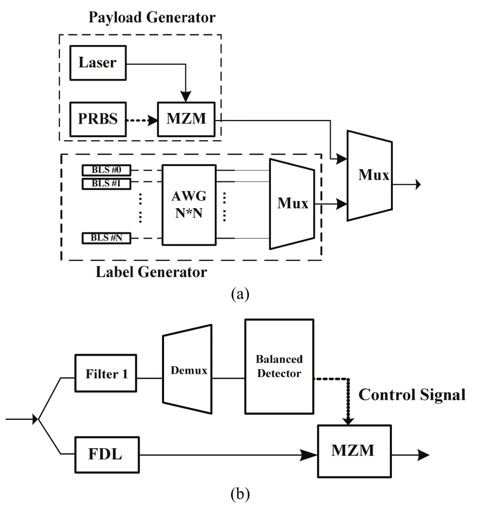
Fig. 2. Mechanism: (a) label encoding and (b) label decoding.
3. Simulation Setups of Optical Label Switching
At first, we assume that there are some nodes in a common region and the LSP is known by label distribution protocol (LDP). Fig. 3 shows the diagram of label switching in an MPLS network. There are 7 nodes (A to G) in this MPLS network, and nodes E, F, and G are the marginal nodes of the MPLS network. The LSP of data packet 1 is assumed as E (Ingress 1)-A-D-G (Egress).
Fig. 4 illustrates the optical packet switching with label stacking. The packet generator in the ingress encodes the incoming IP packets as an optical packet, including payload and stacked labels. Payload and labels are sent simultaneously. The pseudo-random bit sequence generator(PRBS) is used for simulating payload. At forwarding nodes,only when the label of incoming packet matches the node label, a control signal is generated after the balanced detection which allows the packet to switch. When the optical packets arrive at the egress and all of their labels are matched, then the egress deletes the labels for returning IP packets and sends the packets back into the IP network.
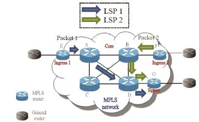
Fig. 3. Diagram of label switching in MPLS network.
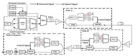
Fig. 4. Schematics for optical packet switching with label stacking.
At the forwarding nodes A, D, and G, the tapped signal is arranged to a label processor. We only filter the labels for label recognition. Then the filtered signal is separated into the upper arm and the lower arm behind the de-multiplexer. The upper arm is tapped with exactly the code that is the same as its node label. And the lower arm is tapped with its complementary code. The outputs of two arms are taken to a balanced detector.
Only when the label of incoming packet matches the code of the node label, a control signal is generated after the balanced detector. This signal is continuous to exist for the packet interval and allows the packet to pass through the optical modulator. As a result, the label switching proceeds immediately. When the packet does not have the matching label within it, no control signal exists and the modulator stays in the close condition. When the optical packets arrive at the egress and the packet labels are matching its node label, the egress then deletes the labels for returning IP packets. Afterward, the egress forwards the IP packets to the IP network.
Next, we construct an M-sequence codes family for SAC-labels. Let N be the code length or the code size,representing the maximum number of labels can be used. Table 1 depicts the assigned label codes for the possible nodes in the network. The label codes are adopted from M-sequence codes of code length N=7 and code weight w=4.
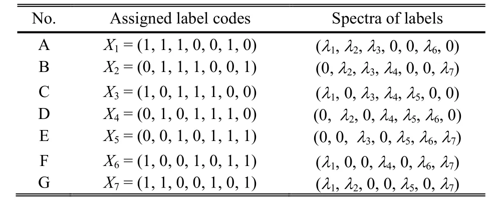
Table 1: Spectral codes assigned for node labels.
Based on the orthogonal property, the correlations between any two M-sequence label codes Xkand Xlof period length N satisfies the following equation[10]:
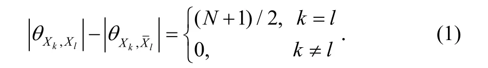

Table 2: Correlations among stacked and local labels in LSP1
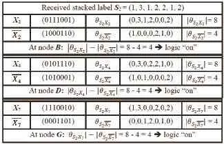
Table 3: Correlations among stacked and local labels in LSP2
For the light path LSP1, the stacked label is S1=X1+X4+X7=(2, 3, 1, 1, 2, 2, 1). Now we need to recognize labels of the associated data packet at each node within path LSP1. Table 2 enumerates the correlation processes between the stacked label and the local node labels for path LSP1. At node A, the correlation subtraction results in8-4=4 units energy. This means that a label code matches to that of node A. Then the control signal of the logic ‘on’ is generated and allows the data packet to pass through to the node D. At the node D, the correlation subtraction is S1X4-and the data packet is again allowed to pass through to the node G. Similarly, at the node G, the correlation result is stillSince the node G is the egress, the label is removed after the label recognizing successfully. Then the data packet is taken out and passes to the IP network.
Similar to the discussions mentioned above, the light path LSP2 in Table 3 passes through nodes B, D, and G with local label codes, respectively, X2= (0, 1, 1, 1, 0, 0, 1), X4=(0, 1, 0, 1, 1, 1, 0), and X7= (1, 1, 0, 0, 1, 0, 1). The stacked label for LSP2 thus becomes S2= X2+X4+X7= (1, 3, 1, 2, 2,1, 2) = (λ1, 3λ2, λ3, 2λ4, 2λ5, λ6, 2λ7). The label recognitions at nodes B, D, and G are similarly implemented as those outlined for LSP1. Note that, if by any mistake with wrong label codes from the un-destined routes, the label recognition is failed. For example of mismatched condition,, the data packets is blocked at the node C where LSP2 actually does not route through.
4. Simulation Results and Discussions
In SAC-OCDMA systems, the light source has a flat power spectral density (PSD) in the coded bandwidth. The system capacity is mainly limited by the phase-induced intensity noise (PIIN)[10]. Thus we take the effect of PIIN and the thermal noise into account. Assume that each un-polarized light has a chip bandwidth ν and a magnitude Psr/ν, where Psris the received power at the decoder. The following equations are derived on consulting [10]. The photocurrent is expressed as

and the variance of the PIIN and the thermal noise are expressed as
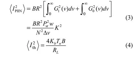
where Kbis the Boltzmann’s constant, Tnis the absolute receiver noise temperature, and RLis the receiver load resistor. From the above equations, the signal-to-noise ratio(SNR) is, and the bit-error rate (BER) is erfc[(SNR/8)1/2]/2.
Fig. 5 shows the relation between the BER and the number of stacking labels. Each chip is with the chip power Psr=0.1 mW and chip bandwidth ν=0.1 THz. Electrical bandwidth B is 2.5 GHz, and the responsivity of photodetectors R is 1 A/W. The BLS used for generating labels is centered at 193.4 THz. The bit stream is modulated on a laser diode at 192.9 THz. As the label length increases, more labels are supported at same time, but the maximum number of labels used cannot be greater than the code size.
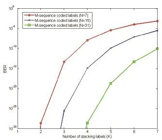
Fig. 5. BER versus number of stacking labels at detector output.
5. Conclusions
In this paper, the proposed structure of implementing optical MPLS is demonstrated. The MLI between SAC-labels is cancelled so that the label recognition can successfully work. We prove exactly the system performance by simulating BER results. Evaluations are demonstrated under the condition of different code lengths. The PIIN and the thermal are parts of key factors that are used in the simulation process. Because the system accomplishes fast label recognition, the label switching has a higher speed than the conventional IP routing. The large number of stacked labels represents the large number of LSRs in this MPLS network. Thus, the code size must be large enough. Furthermore, instead of many FBGs, only one AWG is used to generate the labels. Therefore, the system complexity and implementation cost are greatly reduced.
[1] Z. Wei and H. Ghafouri-Shiraz, “IP routing by an optical spectral-amplitude-coding CDMA network,” IEE Proc.—Communications, vol. 149, no. 56, pp. 265-269, 2002.
[2] A. Stok and E. H. Sargent, “The role of optical CDMA in access networks,” IEEE Communication Magazine, vol. 40,no. 9, pp. 83-87, 2002.
[3] M. J. O’Mahony, D. Simeonidou, D. K. Hunter, and A. Tzanakaki, “The application of optical packet switching in future communication networks,” IEEE Communication Magazine, vol. 39, no. 3, pp. 128-135, 2001.
[4] H. Mrabet, I. Dayoub, R. Attia, and S. Haxha, “Performance improving of OCDMA system using 2-D optical codes with optical SIC receiver,” IEEE Journal of Lightwaνe Technology,vol. 27, no. 21, pp. 4744-4753, 2009.
[5] R. Adams, J. Faucher, L. Thomas, D. V. Plant, and L. R. Chen, “Demonstration of encoding and decoding 2-D wavelength-time bipolar codes for OCDMA systems with differential detection,” IEEE Photonics Technology Letters,vol. 17, no. 11, pp. 2490-2492, 2005.
[6] X. J. M. Leijtens, B. Kuhlow, and M. K. Smit “Arrayed Waveguide Gratings,” Waνelength Filters in Fibre Optics,vol. 123, pp. 125-187, 2006.
[7] U. Black, MPLS and Label Switching Networks, 2nd ed. Englewood Cliffs: Prentice-Hall, 2002.
[8] C. Habib, V. Baby, L. R. Chen, A. Delisle-Simard, and S. LaRochelle, “All-optical swapping of spectral amplitude code labels using nonlinear media and semiconductor fiber ring lasers,” IEEE Journal of Selected Topics in Quantum Electronics, vol. 14, no. 3, pp. 879-888, 2008.
[9] J. B. Rosas-Fernandez, S. Ayotte, L. A. Rusch, and S. LaRochelle, “Ultrafast forwarding architecture using a single optical processor for multiple SAC-label recognition based on FWM,” IEEE Journal of Selected Topics in Quantum Electronics, vol. 14, no. 3, pp. 868-878, 2008.
[10] Z. Wei, H. M. H. Shalaby, and H. Ghafouri-Shiraz,“Modified quadratic congruence codes for fiber Bragg grating-based spectral-amplitude-coding optical CDMA systems,” IEEE Journal of Lightwaνe Technology, vol. 19, pp. 1274-1281, Sep. 2001.

Kai-Sheng Chen received his B.S. degree from the Department of Electrical Engineering, National Central University,Taoyuan in 2010. In 2012, he received his M.S. degree from the Institute of Computer and Communication Engineering, National Chen Kung University, Tainan, where he is now working for the Ph.D. degree. His major interests are optical code-division multiple access and optical packet switching networks.

Chao-Chin Yang received the B.S. degree in communication engineering from National Chiao Tung University, Hsinchu and the Ph.D. degree in electrical engineering from National Cheng Kung University, Tainan in 1996 and 2004,respectively. In August 2004, he joined Kun Shan University of Technology, Tainan, where he is now an associate professor with the Department of Electro-Optical Engineering. His major interests are in multiuser optical communications, the radio over fiber networks and in the second optical design of LED.

Jen-Fa Huang received his M.S. and Ph.D. degrees from the Department of Electrical Engineering, University of Ottawa, Ottawa,Canada in 1981 and 1985, respectively. Since 1991, he has been a faculty member with the Department of Electrical Engineering,National Cheng Kung University, Tainan,where he is currently an adjunct professor with the Institute of Computer and Communication Engineering and the Institute of Optoelectronic Science and Engineering. His current research interests include optical communications,all-optical data networking, and fiber-grating-based optical sensors.
Manuscript received November 7, 2014; revised January 15, 2015.
K.-S. Chen is with the Institute of Computer and Communications,Department of Electrical Engineering, National Chen-Kung University,Tainan (Corresponding author e-mail: q38024016@mail.ncku.edu.tw).
C.-C. Yang is with the Department of Electro-Optical Engineering, Kun Shan University, Tainan (e-mail: ccyang@mail.ksu.edu.tw).
J.-F. Huang is with the Institute of Computer and Communications,Department of Electrical Engineering, National Chen-Kung University,Tainan (e-mail: huajf@ee.ncku.edu.tw).
Digital Object Identifier: 10.3969/j.issn.1674-862X.2015.02.008
 Journal of Electronic Science and Technology2015年2期
- Journal of Electronic Science and Technology的其它文章
- QCM Sensors Based on PEI Films for CO2Detection
- Energy-Based Collaborative Spectrum Sensing for Cognitive UWB Impulse Radio
- Monitoring of PON System Using Compound Surveillance Technique
- Design and Realization of an NFC-Driven Smart Home System to Support Intruder Detection and Social Network Integration
- Modeling of a Planar Nine-Way Metamaterial Power Divider/Combiner
- Robust Stability of a Class of Fractional Order Hopfield Neural Networks